CN210674634U - Jet flow mixing tower for air dust removal - Google Patents
Jet flow mixing tower for air dust removal Download PDFInfo
- Publication number
- CN210674634U CN210674634U CN201921285439.8U CN201921285439U CN210674634U CN 210674634 U CN210674634 U CN 210674634U CN 201921285439 U CN201921285439 U CN 201921285439U CN 210674634 U CN210674634 U CN 210674634U
- Authority
- CN
- China
- Prior art keywords
- air
- dust removal
- mixing tower
- jet flow
- water
- Prior art date
- Legal status (The legal status is an assumption and is not a legal conclusion. Google has not performed a legal analysis and makes no representation as to the accuracy of the status listed.)
- Expired - Fee Related
Links
- 239000000428 dust Substances 0.000 title claims abstract description 49
- 238000002156 mixing Methods 0.000 title claims abstract description 40
- XLYOFNOQVPJJNP-UHFFFAOYSA-N water Substances O XLYOFNOQVPJJNP-UHFFFAOYSA-N 0.000 claims abstract description 66
- 239000003595 mist Substances 0.000 claims abstract description 12
- 238000005192 partition Methods 0.000 claims description 4
- 239000010865 sewage Substances 0.000 claims description 3
- 230000000844 anti-bacterial effect Effects 0.000 claims 1
- 239000007789 gas Substances 0.000 description 11
- 230000001954 sterilising effect Effects 0.000 description 9
- 238000013461 design Methods 0.000 description 4
- 239000003344 environmental pollutant Substances 0.000 description 4
- 231100000719 pollutant Toxicity 0.000 description 4
- 238000000746 purification Methods 0.000 description 4
- 238000004887 air purification Methods 0.000 description 3
- 238000004519 manufacturing process Methods 0.000 description 3
- CBENFWSGALASAD-UHFFFAOYSA-N Ozone Chemical compound [O-][O+]=O CBENFWSGALASAD-UHFFFAOYSA-N 0.000 description 2
- 230000000694 effects Effects 0.000 description 2
- 238000001914 filtration Methods 0.000 description 2
- 238000012423 maintenance Methods 0.000 description 2
- 239000002245 particle Substances 0.000 description 2
- 238000012545 processing Methods 0.000 description 2
- 238000003723 Smelting Methods 0.000 description 1
- 230000009471 action Effects 0.000 description 1
- 150000001450 anions Chemical class 0.000 description 1
- 230000000903 blocking effect Effects 0.000 description 1
- 230000008859 change Effects 0.000 description 1
- 230000007547 defect Effects 0.000 description 1
- 238000011161 development Methods 0.000 description 1
- 238000011049 filling Methods 0.000 description 1
- 239000003517 fume Substances 0.000 description 1
- 238000000227 grinding Methods 0.000 description 1
- 230000036541 health Effects 0.000 description 1
- 238000009434 installation Methods 0.000 description 1
- 238000000034 method Methods 0.000 description 1
- 239000000203 mixture Substances 0.000 description 1
- 239000003921 oil Substances 0.000 description 1
- 238000005498 polishing Methods 0.000 description 1
- 230000008569 process Effects 0.000 description 1
- 239000000779 smoke Substances 0.000 description 1
- 238000005507 spraying Methods 0.000 description 1
- 239000000725 suspension Substances 0.000 description 1
- 239000002912 waste gas Substances 0.000 description 1
Images


Landscapes
- Cyclones (AREA)
- Separation Of Particles Using Liquids (AREA)
Abstract
The utility model discloses a jet flow mixing tower for air dust removal, which comprises a mixing tower body, wherein the mixing tower body is provided with an air suction opening and an air outlet, the air suction opening is provided with an air exhauster, and the air outlet is provided with an air exhauster; a dust removal unit is arranged in the mixing tower and comprises a Venturi tube and a centrifugal cyclone device, one end of the Venturi tube is connected with the air suction opening, the other end of the Venturi tube is connected with the air inlet of the centrifugal cyclone device, and the air outlet of the centrifugal cyclone device is aligned to the air outlet; the water inlet of the water inlet unit is connected with the water storage tank, one end of the Venturi tube close to the suction opening and the air outlet of the centrifugal cyclone device are both connected with the water outlet of the water inlet unit, and the water outlet is provided with a water mist nozzle. The utility model has the advantages that: the jet flow mixing tower for air dust removal has a simple internal structure, reduces the occupation of parts in the internal space of the mixing tower body, and further reduces the volume of the jet flow mixing tower for air dust removal.
Description
Technical Field
The utility model relates to an air dust removal technical field specifically relates to a jet flow thoughtlessly moves tower for air dust removal.
Background
With the rapid development of economy, people pay more attention to the surrounding living environment, especially to the importance of air. In factories, production workshops such as grinding, polishing, spraying waste gas purification pretreatment, industrial oil fume particle purification, smelting dust removal and the like can generate a large amount of polluted gas, and the polluted gas is discharged into the air to directly influence the health of people.
The existing air purification equipment has the defects of complex internal structure, large volume, difficult installation and maintenance and high production cost, so that the design of an air dust removal device with simple structure and small volume is necessary.
Disclosure of Invention
The utility model provides an air removes dust and thoughtlessly moves tower with efflux, its aim at designs a simple structure, small air dust collector.
In order to solve the technical problem, the technical scheme of the utility model as follows:
a jet flow mixing tower for air dust removal comprises a mixing tower body, wherein the mixing tower body is provided with an air suction opening and an air outlet, the air suction opening is provided with an exhaust fan, and the air outlet is provided with an exhaust fan; a dust removal unit is arranged in the mixing tower and comprises a Venturi tube and a centrifugal cyclone device, one end of the Venturi tube is connected with the air suction opening, the other end of the Venturi tube is connected with the air inlet of the centrifugal cyclone device, and the air outlet of the centrifugal cyclone device is aligned to the air outlet; the water inlet of the water inlet unit is connected with the water storage tank, one end of the Venturi tube close to the suction opening and the air outlet of the centrifugal cyclone device are communicated with the water outlet of the water inlet unit, and the water outlet is provided with a water mist nozzle.
Furthermore, the mixing tower body is of a rectangular structure and is divided into an upper layer, a middle layer and a lower layer, the air suction opening and the air exhaust opening are located on the upper layer, the dust removal unit is located on the middle layer, and the lower layer is a water storage tank.
Furthermore, a partition board which completely separates the air suction opening and the air exhaust opening is arranged on the upper layer of the mixing tower body.
Furthermore, the water storage tank extends out of the mixing tower body, the top surface of the water storage tank of the extension part is a notch, and the water storage tank of the extension part is also provided with a sewage draining outlet.
Further, a guide plate is arranged below the centrifugal cyclone device, and a filter tank is arranged at the position of the guide opening of the guide plate.
Furthermore, the filter tank is slidably arranged in the hybrid tower body, and an opening for the filter tank to enter and exit is formed in one side of the hybrid tower body.
Furthermore, 3 dust removal units are arranged in the mixing tower body along the direction of the guide plate.
Furthermore, the suction opening is provided with a filter screen.
Furthermore, a sterilizing lamp is arranged at one end of the Venturi tube close to the centrifugal cyclone device.
Furthermore, a water mist filter screen is arranged at the air outlet.
From the above description of the present invention, compared with the prior art, the advantages of the present invention lie in:
the utility model discloses a efflux thoughtlessly moves tower for air dust removal comprises thoughtlessly moving tower body, venturi, centrifugal whirl device, the unit of intaking, aqua storage tank and the air exhauster that is located air intake department and air exhaust vent, and the air dust removal that adopts this kind of scheme thoughtlessly moves tower inner structure simply with the efflux, reduces the spare part and occupies the inner space that thoughtlessly moves the tower body, and then reduces the air dust removal and thoughtlessly moves the volume of tower with the efflux.
Drawings
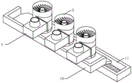
Fig. 1 is a schematic view of the three-dimensional structure of the present invention.
Fig. 2 is a schematic half-section view of fig. 1.
Fig. 3 is a schematic view of the internal structure of the present invention.
Fig. 4 is a schematic structural view of the dust removal unit of the present invention having a guide plate and a filter tank.
Detailed Description
Referring to fig. 1 to 3, a jet flow mixing tower for air dust removal comprises a mixing tower body 1, wherein the mixing tower body 1 is provided with an air suction opening 2 and an air outlet 3, the air suction opening 2 is provided with an exhaust fan (not shown in the figures), and the air outlet 3 is provided with an exhaust fan (not shown in the figures). Mix and move 1 inside dust removal unit that is equipped with of tower, dust removal unit includes venturi 4 and centrifugal swirler 5, and venturi 4's one end is connected with suction opening 2, and the other end and centrifugal swirler 5's air intake connection, and centrifugal swirler 5's air outlet aligns with air exit 3. The technical scheme also comprises a water inlet unit and a water storage tank 6 positioned at the bottom of the hybrid tower body 1. The water inlet unit comprises a main water inlet pipe 7, a plurality of water inlet pipes 8 and a water pump. The total inlet tube 7 is located to the water pump, and the water inlet and the aqua storage tank 6 of total inlet tube 7 are connected, and complex root inlet tube 8 leads to pipe head and total inlet tube 7 intercommunication, and venturi 4 is close to the one end in suction opening and centrifugal swirl device 5's air outlet all links the intercommunication with the delivery port of inlet tube 7, and every delivery port all is equipped with the water smoke shower nozzle.
Has the advantages that: the utility model discloses a efflux thoughtlessly moves tower for air dust removal comprises thoughtlessly moves tower body 1, venturi 4, centrifugal whirl device 5, the unit of intaking, aqua storage tank 6 and the air exhauster (not seen in the figure) that is located suction opening 2, the exhaust fan (not seen in the figure) of air exit 3 department, and the efflux thoughtlessly moves tower for air dust removal who adopts this kind of scheme inside spare part is less, simple structure, not only can reduce manufacturing cost, also easy maintenance when equipment damages; because the internal parts of the utility model are fewer, the internal space of the mixing tower body occupied by the parts is reduced, and the volume of the jet mixing tower for air dust removal is further reduced; because the surface of the tube wall of the Venturi tube 4 is smooth, and the pollutant gas runs dynamically, the common problems of scaling or blocking of equipment and the like can not exist.
The use principle is as follows: when the jet flow mixing tower is used for dedusting, an exhaust fan (not shown in the figure) at an air suction opening 2 introduces external polluted gas into a Venturi tube 4 through the air suction opening 2, meanwhile, a water inlet unit pumps water from a water storage tank 6 and enters the Venturi tube 4 through a water mist nozzle, water mist moves at a high speed along the Venturi tube 4 to be collided and mixed with the water mist in the Venturi tube 4, and if the exhaust fan (not shown) sucks dust-containing gas, the dust is forced to move in the water mist to be wetted or bonded into larger particles, so that the dust loses the suspension capacity in the air and falls down, and the purpose of primarily purifying the land is realized; after the polluted gas is preliminarily purified, the polluted gas is ejected from the outlet end of the Venturi tube 4 at a high speed and enters the centrifugal cyclone device 5, the polluted gas is fully dissolved and adsorbed with each other again under the centrifugal force action of the centrifugal cyclone device 5 in the high-speed dynamic operation, the purification purpose is achieved through the cyclone energy of circular motion, and finally, the purified gas is discharged from the air outlet 3 by an exhaust fan (not shown in the figure). In the air purification process, water can reenter the water storage tank 6 from the centrifugal cyclone device 5, so that the water can be recycled, and water resources are saved. The water storage tank 6 can be filled with water and ozone solution, and the specific filling of the solution depends on pollutants in the air.
Referring to fig. 1 and 3, the mixing tower body 1 is a rectangular structure and is divided into an upper layer, a middle layer and a lower layer, the suction opening 2 and the exhaust opening 3 are located at the upper layer, the dust removal unit is located at the middle layer, and the lower layer is a water storage tank 6. Adopt the thoughtlessly move tower body 1 of this kind of structure, aqua storage tank 6 does not need to install aqua storage tank 6 in addition with thoughtlessly move tower body 1 integrated into one piece, makes the utility model discloses a structure is compacter.
Referring to fig. 3, a partition 9 for completely separating the suction opening 2 and the exhaust opening 3 is provided at the upper layer of the mixing tower body 1. The partition board 9 is adopted to completely separate the air suction opening 2 from the air exhaust opening 3, so that the purified gas can not be reintroduced into the dust removal unit by the exhaust fan (not shown in the figure), and the dust removal efficiency is improved.
Referring to fig. 1 and 3, the water storage tank 6 extends out of the hybrid tower body 1, the top surface of the water storage tank 6 of the extension part is a gap, and the water storage tank 6 of the extension part is further provided with a sewage discharge outlet. The accessible extends the quality of water condition in the 6 top surfaces of outside aqua storage tank to observe, if observe quality of water not up to standard, just can discharge with the drain, and the back is completely discharged to the water, adds clean water again in 6 through the breach toward aqua storage tank.
Referring to fig. 1 and 4, a guide plate 10 is arranged below the centrifugal cyclone device 5, and a filter tank 11 is arranged at a guide opening of the guide plate 10. Through the arrangement of the guide plate 10 and the filter tank 11, pollutants in water can be filtered, so that high-quality water quality is provided for the purification unit. The filter tank 11 can be slidably disposed in the hybrid tower body 1 through a slide rail pair or a guide rail pair, and an opening 12 for the filter tank 11 to enter and exit is disposed on one side of the hybrid tower body 1, for example, a pulley is disposed at the bottom of the filter tank 11, and a guide rail is disposed at a position of the hybrid tower body 1 corresponding to the filter tank 11. When too much pollutant is piled up in the filter tank 11, the filter tank 11 is drawn out through the arrangement of the sliding structure, so that the filter tank 11 is convenient to clean. The slidable structure belongs to a structure common in real life, and the detailed description is omitted.
Referring to fig. 2 and 4, in the embodiment, 3 dust removing units are arranged in the mixing tower body 1, and the 3 dust removing units are arranged along the direction of the flow guide plate 10. The plurality of dust removal units are arranged, so that the working efficiency can be improved. The number of the dust removing units is determined according to the amount of the pollution gas generated at the processing place, and is not limited to 3.
Referring to fig. 2 to 4, in order to further increase the filtering effect, a filtering net (not shown) may be disposed at the air suction opening 2; a sterilizing lamp (not shown in the figure) is arranged at the inner position of the venturi tube 4 close to the centrifugal cyclone device 5, the sterilizing lamp can be a plasma generator sterilizing lamp, an ultraviolet sterilizing lamp, an ozone generator sterilizing lamp or an anion generator sterilizing lamp, and the corresponding sterilizing lamp is arranged according to pollution generated in different processing places; a water mist filter screen 12 can be arranged on the upper layer of the mixing tower body 1 and below the air outlet 3. The air purification effect can be further improved by arranging a filter screen (not shown) at the air suction opening 2 and a sterilizing lamp (not shown) at the position of the Venturi tube 4 close to the centrifugal cyclone device 5. The arrangement of the water mist filter screen 12 can prevent water mist from being discharged from the air outlet 3 and prevent overhigh humidity of a workshop.
The above-mentioned be the utility model discloses a concrete implementation way, nevertheless the utility model discloses a design concept is not limited to this, and the ordinary use of this design is right the utility model discloses carry out immaterial change, all should belong to the act of infringement the protection scope of the utility model.
Claims (10)
1. The utility model provides an air removes dust and thoughtlessly moves tower with efflux which characterized in that: the mixed-action tower comprises a mixed-action tower body, wherein the mixed-action tower body is provided with an air suction opening and an air outlet, the air suction opening is provided with an exhaust fan, and the air outlet is provided with an exhaust fan; a dust removal unit is arranged in the mixing tower and comprises a Venturi tube and a centrifugal cyclone device, one end of the Venturi tube is connected with the air suction opening, the other end of the Venturi tube is connected with the air inlet of the centrifugal cyclone device, and the air outlet of the centrifugal cyclone device is aligned to the air outlet; the water inlet of the water inlet unit is connected with the water storage tank, one end of the Venturi tube close to the suction opening and the air outlet of the centrifugal cyclone device are communicated with the water outlet of the water inlet unit, and the water outlet is provided with a water mist nozzle.
2. The jet flow mixing tower for air dust removal according to claim 1, wherein: the mixing tower body is of a rectangular structure and is divided into an upper layer, a middle layer and a lower layer, the air suction opening and the air exhaust opening are located on the upper layer, the dust removal unit is located on the middle layer, and the lower layer is a water storage tank.
3. The jet flow mixing tower for air dust removal according to claim 2, wherein: the upper layer of the mixing tower body is provided with a partition board which completely separates the air suction opening from the air outlet.
4. The jet flow mixing tower for air dust removal according to claim 2, wherein: the water storage tank extends out of the mixing tower body, the top surface of the water storage tank of the extension part is a notch, and the water storage tank of the extension part is also provided with a sewage draining outlet.
5. The jet flow mixing tower for air dust removal according to any one of claims 1 to 4, wherein: the centrifugal cyclone device is characterized in that a guide plate is arranged below the centrifugal cyclone device, and a filter tank is arranged at the position of a guide opening of the guide plate.
6. The jet flow mixing tower for air dust removal according to claim 5, wherein: the filter tank is slidably arranged in the hybrid tower body, and one side of the hybrid tower body is provided with an opening for the filter tank to enter and exit.
7. The jet flow mixing tower for air dust removal according to claim 6, wherein: the tower body that thoughtlessly moves is equipped with 3 dust removal units along the guide plate direction.
8. The jet flow mixing tower for air dust removal according to claim 7, wherein: and a filter screen is arranged at the air suction opening.
9. The jet flow mixing tower for air dust removal according to claim 7, wherein: and a bactericidal lamp is arranged at one end of the Venturi tube close to the centrifugal cyclone device.
10. The jet flow mixing tower for air dust removal according to claim 7, wherein: and a water mist filter screen is arranged at the air outlet.
Priority Applications (1)
| Application Number | Priority Date | Filing Date | Title |
|---|---|---|---|
| CN201921285439.8U CN210674634U (en) | 2019-08-08 | 2019-08-08 | Jet flow mixing tower for air dust removal |
Applications Claiming Priority (1)
| Application Number | Priority Date | Filing Date | Title |
|---|---|---|---|
| CN201921285439.8U CN210674634U (en) | 2019-08-08 | 2019-08-08 | Jet flow mixing tower for air dust removal |
Publications (1)
| Publication Number | Publication Date |
|---|---|
| CN210674634U true CN210674634U (en) | 2020-06-05 |
Family
ID=70896601
Family Applications (1)
| Application Number | Title | Priority Date | Filing Date |
|---|---|---|---|
| CN201921285439.8U Expired - Fee Related CN210674634U (en) | 2019-08-08 | 2019-08-08 | Jet flow mixing tower for air dust removal |
Country Status (1)
| Country | Link |
|---|---|
| CN (1) | CN210674634U (en) |
Cited By (2)
| Publication number | Priority date | Publication date | Assignee | Title |
|---|---|---|---|---|
| CN114288728A (en) * | 2021-12-27 | 2022-04-08 | 扬州星辰环境工程有限公司 | High-efficiency jet flow mixing tower |
| CN115253564A (en) * | 2022-09-02 | 2022-11-01 | 青岛福荣华鑫环保能源科技有限公司 | Jet flow mixed-moving dust remover for sludge dryer |
-
2019
- 2019-08-08 CN CN201921285439.8U patent/CN210674634U/en not_active Expired - Fee Related
Cited By (2)
| Publication number | Priority date | Publication date | Assignee | Title |
|---|---|---|---|---|
| CN114288728A (en) * | 2021-12-27 | 2022-04-08 | 扬州星辰环境工程有限公司 | High-efficiency jet flow mixing tower |
| CN115253564A (en) * | 2022-09-02 | 2022-11-01 | 青岛福荣华鑫环保能源科技有限公司 | Jet flow mixed-moving dust remover for sludge dryer |
Similar Documents
| Publication | Publication Date | Title |
|---|---|---|
| CN204584980U (en) | Environmental protection dust removal workbench | |
| CN103877804A (en) | Water tank for filtering tail gas dust | |
| CN215782471U (en) | Jet flow mixed-moving two-stage spraying pretreatment device | |
| CN111265953A (en) | A grinding and dust removal device for die castings | |
| CN213314004U (en) | An environmentally friendly filter and dust removal equipment | |
| CN202962190U (en) | Welding dedusting and purifying device | |
| CN214051006U (en) | Silencing dust remover | |
| CN212651550U (en) | Venturi scrubber with overflow type built-in circulating tank | |
| CN205308039U (en) | Wet dust collector | |
| CN110953625B (en) | Water curtain type vortex oil smoke purifier | |
| CN210495543U (en) | No-consumable maintenance-free self-cleaning vortex type oil mist purifier | |
| CN219942290U (en) | Wet multitube cyclone dust collector | |
| CN203303793U (en) | Soot capturing and purifying device | |
| CN203790768U (en) | Tail gas dust filter water tank | |
| CN207385146U (en) | Jetting type wet method fume purifier of fume | |
| CN215782470U (en) | Cyclone mixed single-stage spraying pretreatment device | |
| CN215311228U (en) | Large-scale industrial purification filter | |
| CN213349474U (en) | Automatic water lifting paint spray booth paint mist treatment system | |
| CN216909699U (en) | Spray catalytic purifier | |
| CN206027334U (en) | Improved generation sanding room dust collecting equipment | |
| CN204799035U (en) | Dust pelletizing system | |
| CN211502930U (en) | Water curtain type vortex oil fume purifier | |
| CN111375258B (en) | Foam centrifugal dust collector and exhaust gas treatment system | |
| CN211913050U (en) | Self-cleaning type filtering device for waste gas treatment | |
| CN210251733U (en) | Multiple filterable paint tail gas processing apparatus |
Legal Events
| Date | Code | Title | Description |
|---|---|---|---|
| GR01 | Patent grant | ||
| GR01 | Patent grant | ||
| CP01 | Change in the name or title of a patent holder |
Address after: No. 41, Wufu Industrial Zone, Pingnan Meiyuan, Guicheng, Nanhai District, Foshan City, Guangdong Province Patentee after: Guangdong Tianqing Jiayuan Environmental Technology Co.,Ltd. Address before: No. 41, Wufu Industrial Zone, Pingnan Meiyuan, Guicheng, Nanhai District, Foshan City, Guangdong Province Patentee before: FOSHAN TIANQING JIAYUAN ENVIRONMENTAL PROTECTION TECHNOLOGY Co.,Ltd. |
|
| CP01 | Change in the name or title of a patent holder | ||
| CF01 | Termination of patent right due to non-payment of annual fee |
Granted publication date: 20200605 |
|
| CF01 | Termination of patent right due to non-payment of annual fee |