Automatic change circuit board apparatus for producing
Technical Field
The utility model relates to an automated production technical field specifically is to relate to an automatic change circuit board apparatus for producing.
Background
At present, with the development of science and technology in China, circuit boards are gradually developed towards densification and integration, but in the cutting process of the circuit boards, workers carry out manual feeding, manual operation equipment cuts one circuit board, the feeding efficiency is low and the cutting efficiency is low in the cutting mode, so that the production efficiency of the circuit boards is influenced, and the manual operation has certain dangerousness.
SUMMERY OF THE UTILITY MODEL
The utility model aims to solve the technical problem that an automatic change circuit board apparatus for producing is provided.
In order to solve the technical problem, the utility model provides a following technical scheme:
an automatic circuit board production device comprises a processing table, a screw rod sliding table, a feeding mechanism, a cutting mechanism and a discharging mechanism, the screw rod sliding table is arranged at the top of the processing table, a connecting block is arranged on the sliding table of the screw rod sliding table, two U-shaped positioning plates which are symmetrically arranged are arranged on the connecting block, the feeding mechanism and the cutting mechanism are sequentially arranged on the processing table along the conveying direction of the screw rod sliding table, feed mechanism is including holding the frame and two backup pads that are the L type, and two backup pads symmetries set up on holding the frame, and the top of every backup pad all is equipped with the first mounting panel that is vertical setting, all is equipped with first blowing subassembly on every first mounting panel, and the top below of every backup pad all is equipped with the second mounting panel that is vertical setting, all is equipped with second blowing subassembly on every second mounting panel, unloading mechanism installs on the front end of processing platform.
Preferably, first blowing subassembly and second blowing subassembly's the same structure and all include blowing cylinder and T type piece, the blowing cylinder is the level setting, hold be equipped with on the lateral wall of frame with T type piece sliding fit's spout, the output of blowing cylinder and the back fixed connection of T type piece.
Preferably, cutting mechanism includes cutting motor, mount pad, pivot, first sprocket, second sprocket, cutting knife and is the support frame of U type, the top at the processing platform is installed to the support frame, the mount pad is installed on the support frame, the pivot is rotated and is installed on the mount pad, one of pivot serve with rather than coaxial line's mounting disc, the cutting knife is installed on the mounting disc, the top of support frame is equipped with the groove of wearing that supplies the cutting knife to pass, the other end at the pivot is installed to first sprocket, cutting motor is located the side of mount pad, the second sprocket is installed on cutting motor's output, the second sprocket passes through chain drive with first sprocket and is connected.
Preferably, unloading mechanism includes lifting subassembly, turns to subassembly and centre gripping subassembly, the front end of processing platform is equipped with the fixed plate that is the level setting, the lifting unit mount is in the bottom of fixed plate, turn to the unit mount on the lifting subassembly, centre gripping unit mount turns to on the subassembly.
Preferably, the lifting subassembly includes the third mounting panel of lifting electric putter and U type, lifting electric putter is the vertical bottom of installing at the fixed plate, the third mounting panel is installed on lifting electric putter's output, the bottom of third mounting panel is equipped with four first guide bars that are the rectangle and distribute, the bottom of fixed plate is equipped with four and four first guide bar one-by-one direction complex first guide holder, turn to the subassembly including turning to motor and loading board, turn to the motor and be vertical top below of installing at the third mounting panel, the loading board is horizontal installation on the output that turns to the motor.
Preferably, the centre gripping subassembly includes translation electric putter, is the fourth mounting panel and four centre gripping cylinders of U type, be equipped with the riser on the loading board, translation electric putter is horizontal installation on the riser, the fourth mounting panel is installed on translation electric putter's output, the middle part of fourth mounting panel is equipped with the extension board that is vertical setting, and two centre gripping cylinder symmetries set up on the fourth mounting panel, and two other centre gripping cylinders are installed respectively on the both sides wall of extension board, the back of fourth mounting panel is equipped with the second guide bar that two symmetries set up, be equipped with two on the riser with two second guide bar one by one direction complex second guide holders.
Compared with the prior art, the utility model beneficial effect who has is:
one of which, the utility model discloses a circuit board in the frame is held can be emitted automatically in the cooperation of two second blowing subassemblies, carry out reciprocating motion once all through blowing cylinder drive T type piece, T type piece can support and press on the lateral wall of circuit board, two T type pieces can support and press on the both sides wall of circuit board, thereby let all circuit boards of this circuit board top spacing, two T type pieces support the circuit board of pressing and lose the free landing down of clamping-force, next T type piece is just again by two T type piece centre grippings, thereby realized automatic feeding, two first blowing subassemblies can carry on spacingly to the circuit board that holds first one of the frame, thereby the blowing burden of two second blowing subassemblies has been reduced.
Two, the utility model discloses a lead screw slip table is when the transfer chain circuit board, and cutting device can once only cut all circuit boards, has improved the efficiency of cutting.
Third, the utility model discloses when the unloading, translation electric putter is to the circuit board drive, two centre gripping cylinders just can the centre gripping to half one on the left side of all circuit boards, two other centre gripping cylinders just can the centre gripping to half one on the right side of all circuit boards, later lifting electric putter drive third mounting panel, turn to subassembly and centre gripping subassembly and rise, half one on the left side of the circuit board of centre gripping subassembly centre gripping and half one on the right side have broken away from two U type locating plates along with rising, later turn to the motor drive loading board and rotate, the loading board can drive and be rotated by the circuit board of centre gripping in step, thereby realized that the circuit board that will cut has carried out automatic unloading.
Drawings
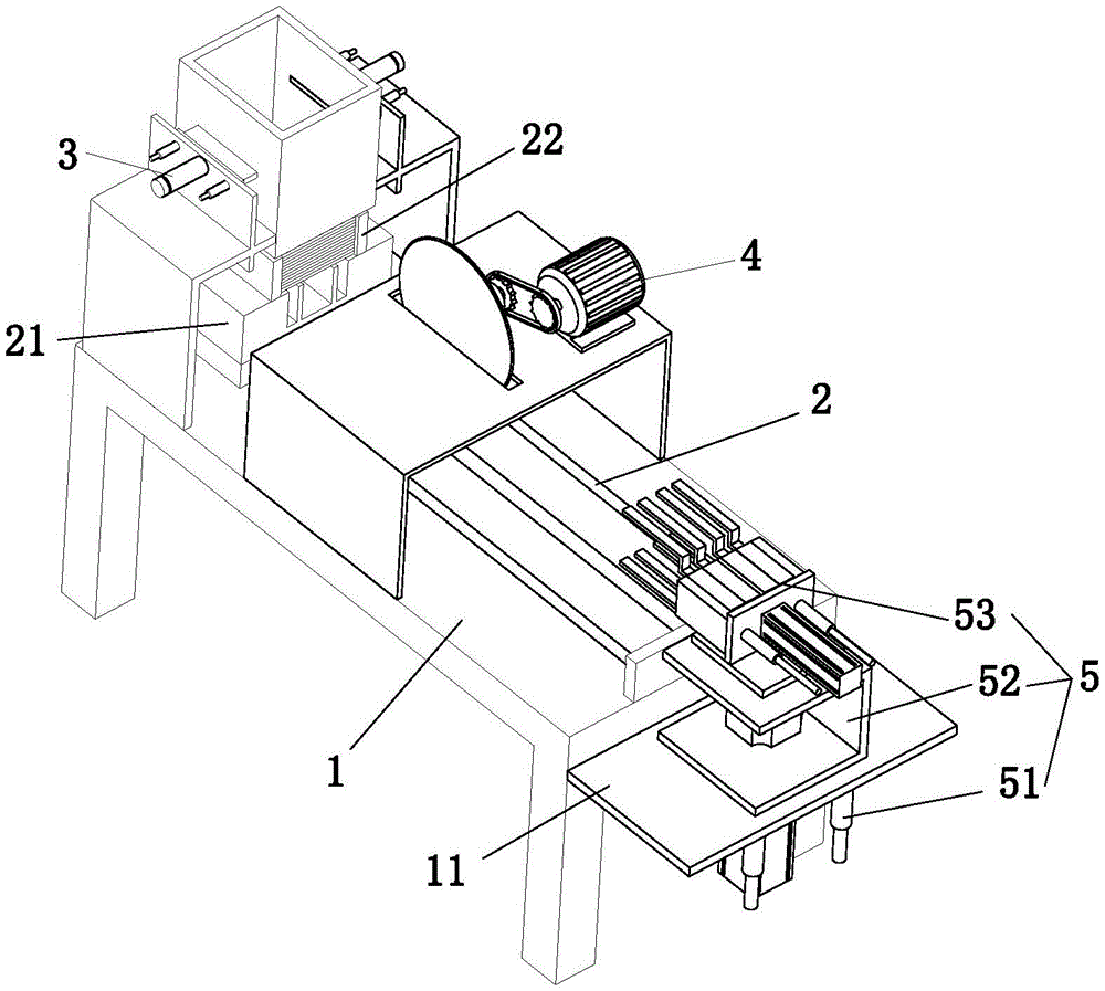
Fig. 1 is a first perspective view of the present invention;
fig. 2 is a side view of the present invention;
fig. 3 is a second schematic perspective view of the present invention;
the reference numbers in the figures are: the machining table 1, the fixing plate 11, the first guide seat 111, the screw rod sliding table 2, the connecting block 21, the avoiding groove 211, the notch 212, the U-shaped positioning plate 22, the feeding mechanism 3, the accommodating frame 31, the supporting plate 32, the first mounting plate 321, the second mounting plate 322, the first discharging component 33, the discharging cylinder 331, the T-shaped block 332, the second discharging component 34, the cutting mechanism 4, the cutting motor 41, the mounting seat 42, the rotating shaft 43, the mounting plate 431, the first chain wheel 44, the second chain wheel 45, the cutting knife 46, the supporting frame 47, the through groove 471, the discharging mechanism 5, the lifting component 51, the lifting electric push rod 511, the third mounting plate 512, the first guide rod 5121, the steering component 52, the steering motor 521, the bearing plate 522, the vertical plate 5221, the second guide seat 5222, the clamping component 53, the translation electric push rod 531, the fourth mounting plate 532, the extension plate 5321, the second guide rod 5322 and the clamping cylinder 533.
Detailed Description
In order to make the objects, technical solutions and advantages of the present invention more clearly understood, the present invention is further described in detail below with reference to the accompanying drawings and embodiments. It should be understood that the specific embodiments described herein are merely illustrative of the invention and are not intended to limit the invention.
Referring to fig. 1 to 3, an automatic circuit board production device comprises a processing table 1, a screw rod sliding table 2, a feeding mechanism 3, a cutting mechanism 4 and a blanking mechanism 5, wherein the screw rod sliding table 2 is installed at the top of the processing table 1, a connecting block 21 is installed on the sliding table of the screw rod sliding table 2, two U-shaped positioning plates 22 which are symmetrically arranged are arranged on the connecting block 21, the feeding mechanism 3 and the cutting mechanism 4 are sequentially arranged on the processing table 1 along the conveying direction of the screw rod sliding table 2, the feeding mechanism 3 comprises a containing frame 31 and two L-shaped supporting plates 32, the two supporting plates 32 are symmetrically arranged on the containing frame 31, a first mounting plate 321 which is vertically arranged is arranged at the top of each supporting plate 32, a first discharging assembly 33 is arranged on each first mounting plate 321, a second mounting plate 322 which is vertically arranged is arranged below the top of each supporting plate 32, each second mounting plate 322 is provided with a second discharging assembly 34, and the discharging mechanism 5 is mounted at the front end of the processing table 1; place the circuit board with the horizontally state and hold in the frame 31, two second blowing subassemblies 34 cooperation can carry out the blowing in proper order with holding all circuit boards in the frame 31, in order to reduce the burden of two second blowing subassemblies 34, the cooperation of two first blowing subassemblies 33 can be spacing to holding the circuit board of first half of frame 31, the circuit board of discharging from holding the frame 31 falls into between two U type locating plates 22 in proper order, later lead screw slip table 2 can drive connecting block 21 and be located all circuit boards between two U type locating plates 22 and remove to cutting mechanism 4, cutting mechanism 4 can carry out automatic cutout with all circuit boards that are located between two U type locating plates 22, after the cutting is accomplished, circuit board automatic handling after the cutting is accomplished through unloading mechanism 5.
Specifically, the first emptying assembly 33 and the second emptying assembly 34 have the same structure and respectively comprise an emptying cylinder 331 and a T-shaped block 332, the emptying cylinder 331 is horizontally arranged, a sliding groove in sliding fit with the T-shaped block 332 is arranged on the side wall of the accommodating frame 31, and the output end of the emptying cylinder 331 is fixedly connected with the back of the T-shaped block 332; blowing cylinder 331 can drive T type piece 332 and remove in the spout, T type piece 332 can support and press on the lateral wall of circuit board, two T type pieces 332 can support and press on the both sides wall of circuit board, thereby let all circuit boards of this circuit board top by spacing, when the blowing of needs, blowing cylinder 331 drives T type piece 332 and carries out reciprocating motion once around, thereby let the circuit board that is supported and pressed by two T type pieces 332 lose the free landing downwards of clamping-force, next T type piece 332 is just again by two T type piece 332 centre grippings.
Specifically, the cutting mechanism 4 includes a cutting motor 41, a mounting seat 42, a rotating shaft 43, a first chain wheel 44, a second chain wheel 45, a cutting knife 46 and a U-shaped supporting frame 47, the supporting frame 47 is mounted at the top of the processing table 1, the mounting seat 42 is mounted on the supporting frame 47, the rotating shaft 43 is rotatably mounted on the mounting seat 42, one end of the rotating shaft 43 is provided with a mounting disc 431 coaxial with the rotating shaft 43, the cutting knife 46 is mounted on the mounting disc 431, the top of the supporting frame 47 is provided with a through groove 471 for the cutting knife 46 to pass through, the first chain wheel 44 is mounted at the other end of the rotating shaft 43, the cutting motor 41 is located beside the mounting seat 42, the second chain wheel 45 is mounted at the output end of the cutting motor 41, and the second chain wheel 45 is connected with the first chain wheel 44 through chain transmission; cutting motor 41 drives second sprocket 45 and rotates, and second sprocket 45 drives first sprocket 44 through the chain and rotates, and first sprocket 44 drives mounting disc 431 and cutting knife 46 and rotates, and cutting knife 46 can carry out automatic cutout with the circuit board that is located between two U type locating plates 22, in order to avoid cutting knife 46 to cut connecting block 21, has designed on the connecting block 21 and has dodged groove 211, as shown in fig. 3.
Specifically, the blanking mechanism 5 comprises a lifting assembly 51, a steering assembly 52 and a clamping assembly 53, the front end of the processing table 1 is provided with a horizontally arranged fixing plate 11, the lifting assembly 51 is installed at the bottom of the fixing plate 11, the steering assembly 52 is installed on the lifting assembly 51, and the clamping assembly 53 is installed on the steering assembly 52; the lifting assembly 51 can lift the clamping assembly 53, and the steering assembly 52 can drive the clamping assembly 53 to steer between 90 and 180 degrees.
Specifically, lifting subassembly 51 includes the third mounting panel 512 of lifting electric putter 511 and U type, lifting electric putter 511 is the vertical bottom of installing at fixed plate 11, third mounting panel 512 is installed on lifting electric putter 511's output, the bottom of third mounting panel 512 is equipped with four first guide bars 5121 that are the rectangular distribution, the bottom of fixed plate 11 is equipped with four and four first guide bars 5121 one by one direction complex first guide holder 111, turn to subassembly 52 including turning to motor 521 and loading board 522, it is vertical the top below of installing at third mounting panel 512 to turn to motor 521, loading board 522 is horizontal installation on the output that turns to motor 521.
Specifically, the centre gripping subassembly 53 includes translation electric putter 531, is the fourth mounting panel 532 and four centre gripping cylinders 533 of U type, be equipped with riser 5221 on the loading board 522, translation electric putter 531 is horizontal installation on riser 5221, fourth mounting panel 532 is installed on the output of translation electric putter 531, the middle part of fourth mounting panel 532 is equipped with the extension board 5321 that is vertical setting, and two centre gripping cylinders 533 symmetries set up on fourth mounting panel 532, and other two centre gripping cylinders 533 are installed respectively on the both sides wall of extension board 5321, the back of fourth mounting panel 532 is equipped with the second guide bar 5322 that two symmetries set up, be equipped with two and two second guide bar 5322 one-to-one direction complex second guide holder 5222 on riser 5221.
By integrating the three sections, when the lead screw sliding table 2 conveys the cut circuit board to the blanking device, the translational electric push rod 531 drives the circuit board, the two clamping cylinders 533 can just clamp the left half parts of all the circuit boards, the other two clamping cylinders 533 can just clamp the right half parts of all the circuit boards, so in order to avoid the clamping cylinders 533 from colliding with the connecting block 21, the connecting block 21 is designed with notches 212, as shown in fig. 3, the electric push rod 511 is lifted to drive the third mounting plate 512, the steering assembly 52 and the clamping assembly 53 to ascend, the left half part and the right half part of the circuit board clamped by the clamping assembly 53 are separated from the two U-shaped positioning plates 22 along with ascending, then the steering motor 521 drives the bearing plate 522 to rotate, and the bearing plate 522 can drive the clamped circuit board to synchronously rotate, so that automatic blanking of the cut circuit board is realized.