CN210657202U - Stable and adjustable hanging tool for surface treatment of bicycle aluminum ring - Google Patents
Stable and adjustable hanging tool for surface treatment of bicycle aluminum ring Download PDFInfo
- Publication number
- CN210657202U CN210657202U CN201921405383.5U CN201921405383U CN210657202U CN 210657202 U CN210657202 U CN 210657202U CN 201921405383 U CN201921405383 U CN 201921405383U CN 210657202 U CN210657202 U CN 210657202U
- Authority
- CN
- China
- Prior art keywords
- support rod
- article
- rod
- surface treatment
- upper support
- Prior art date
- Legal status (The legal status is an assumption and is not a legal conclusion. Google has not performed a legal analysis and makes no representation as to the accuracy of the status listed.)
- Expired - Fee Related
Links
- AZDRQVAHHNSJOQ-UHFFFAOYSA-N alumane Chemical group [AlH3] AZDRQVAHHNSJOQ-UHFFFAOYSA-N 0.000 title claims abstract description 30
- 238000004381 surface treatment Methods 0.000 title claims abstract description 18
- XAGFODPZIPBFFR-UHFFFAOYSA-N aluminium Chemical compound [Al] XAGFODPZIPBFFR-UHFFFAOYSA-N 0.000 claims abstract description 6
- 229910052782 aluminium Inorganic materials 0.000 claims abstract description 6
- 239000004411 aluminium Substances 0.000 claims abstract description 5
- 238000009713 electroplating Methods 0.000 description 4
- 238000000034 method Methods 0.000 description 3
- 230000004048 modification Effects 0.000 description 2
- 238000012986 modification Methods 0.000 description 2
- 238000007747 plating Methods 0.000 description 2
- 230000007797 corrosion Effects 0.000 description 1
- 238000005260 corrosion Methods 0.000 description 1
- 230000007547 defect Effects 0.000 description 1
Images
Landscapes
- Holders For Apparel And Elements Relating To Apparel (AREA)
Abstract
The utility model relates to a hanger technical field for bicycle aluminium circle surface treatment especially relates to a stabilize adjustable hanger for bicycle aluminium circle surface treatment. The side rack is slidably connected with the connecting rod, and the connecting rod is provided with the clamping spring, so that bicycle aluminum rings with different sizes can be clamped, and the problem that the bicycle aluminum rings are easy to fall off due to small stress is solved; the power-assisted spring is used between the upper support rod and the lower support rod, the function of utilizing the upward tension of the power-assisted spring after the bicycle aluminum ring is loaded is realized, and the problem that the hanger is heavy and is not convenient to reset when the load is too much is solved.
Description
Technical Field
The utility model relates to a hanger technical field for bicycle aluminium circle surface treatment especially relates to a stabilize adjustable hanger for bicycle aluminium circle surface treatment.
Background
The surface of the bicycle aluminum ring needs to be electroplated, and the electroplated bicycle aluminum ring has high hardness, single and uniform color and strong corrosion resistance.
The existing hanger for surface treatment of the bicycle aluminum ring is only hung by utilizing the weight of the bicycle aluminum ring, the force applied to the bicycle aluminum ring is small, and the aluminum ring can fall off due to bubbles generated when the aluminum ring is placed in the plating tank containing the electroplating solution or in the electroplating process; the rack is heavy and difficult to reset after the aluminum rings of the bicycle are loaded.
SUMMERY OF THE UTILITY MODEL
The utility model aims to solve the technical problem that the technical defects exist, and provides a stable and adjustable hanging tool for surface treatment of bicycle aluminum rings, which adopts a side rack to be slidably connected with a connecting rod, and the connecting rod is provided with a clamping spring, thereby realizing the function that the bicycle aluminum rings with different sizes can be clamped, and solving the problem that the bicycle aluminum rings are small in stress and easy to fall off; the power spring is used between the upper support rod and the lower support rod, the function that the power spring can be used for resetting the hanger after the aluminum ring of the bicycle is loaded is achieved, and the problem that the hanger is heavy and inconvenient to reset when the load is too much is solved.
In order to solve the technical problem, the utility model discloses the technical scheme who adopts is: comprises a connecting part and an object placing part; the connecting part comprises an upper support rod and a lower support rod; a sliding groove is formed in one side, close to the lower support rod, of the upper support rod; a first limiting hole is formed in one side, away from the lower support rod, of the sliding chute; a second limiting hole is formed in the other side of the sliding groove; one end of the lower support rod, which is close to the upper support rod, is provided with a limiting rod; the limiting rod is connected with the sliding groove in a sliding manner; the lower end of the upper supporting rod is provided with an object placing part; the upper support rod and the object placing part are welded; the lower end of the lower support rod is provided with an object placing part; the lower support rod and the object placing part are welded; the article placing part comprises a middle article placing rack and side article placing racks; side article racks are arranged on two sides of the middle article rack; the two sides of the middle article shelf are provided with connecting rods; the side article rack is connected with the connecting rod in a sliding way; a clamping spring is arranged on the outer side of the connecting rod; one side of the clamping spring is welded with the middle article placing rack; the other side of the clamping spring is welded with the side article rack; the opposite inner sides of the middle article shelf and the side article shelves are provided with article slots.
Further optimize this technical scheme, it is provided with the couple to go up the branch upper end.
Further optimizing the technical scheme, the upper supporting rod adopts a hollow structure; a power-assisted spring is arranged in the upper supporting rod; the power spring and the upper support rod are welded; and the power-assisted spring and the lower support rod are welded.
Further optimize this technical scheme, the gag lever post both ends are provided with fastening nut.
Further optimize this technical scheme, the connecting rod both ends are provided with stop nut.
Further optimize this technical scheme, it is hollow structure to put the thing groove.
Compared with the prior art, the utility model has the advantages of it is following: 1. the side rack is slidably connected with the connecting rod, and the connecting rod is provided with the clamping spring, so that the aluminum rings of the bicycles with different sizes can be clamped, and the aluminum rings of the bicycles are not easy to fall off in the surface treatment process; 2. the power-assisted spring is used between the upper support rod and the lower support rod, so that the function of resetting the hanger by utilizing the upward tension of the power-assisted spring after the aluminum ring of the bicycle is loaded is realized, and the heavy hanger is easy to reset when the load is too much.
Drawings
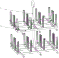
Fig. 1 is a schematic view of the overall structure of a stable and adjustable hanger for surface treatment of an aluminum ring of a bicycle.
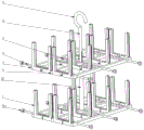
Fig. 2 is a schematic view of a storage part of a stable and adjustable rack for surface treatment of an aluminum ring of a bicycle.
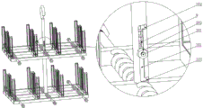
FIG. 3 is an enlarged schematic view of a connecting portion of a stable and adjustable hanger for surface treatment of an aluminum rim of a bicycle.
In the figure: 1. a connecting portion; 2. an article placing part; 11. an upper support rod; 22. a lower support rod; 3. a middle rack; 4. a side rack; 5. a connecting rod; 6. a chucking spring; 7. a storage groove; 8. hooking; 9. a power-assisted spring; 101. a chute; 102. a first limit hole; 103. a second limiting hole; 201. a limiting rod; 202. fastening a nut; 501. and a limiting nut.
Detailed Description
In order to make the objects, technical solutions and advantages of the present invention more apparent, the present invention will be described in detail with reference to the accompanying drawings. It should be understood that the description is intended to be illustrative only and is not intended to limit the scope of the present invention. Moreover, in the following description, descriptions of well-known structures and techniques are omitted so as to not unnecessarily obscure the concepts of the present invention.
The specific implementation mode is as follows: as shown in fig. 1-3, the device comprises a connecting part 1 and an object placing part 2; the connecting part comprises an upper support rod 11 and a lower support rod 22; a sliding groove 101 is formed in one side, close to the lower supporting rod 22, of the upper supporting rod 11; a first limiting hole 102 is formed in one side, away from the lower support rod 22, of the sliding groove 101; a second limiting hole 103 is formed in the other side of the sliding groove 101; one end of the lower support rod 22 close to the upper support rod 11 is provided with a limiting rod 201; the limiting rod 201 is connected with the sliding groove 101 in a sliding mode; the lower end of the upper support rod 11 is provided with an article placing part 2; the upper support rod 11 and the object placing part 2 are welded; the lower end of the lower supporting rod 22 is provided with an object placing part 2; the lower support rod 22 and the object placing part 2 are welded; the article placing part 2 comprises a middle article placing rack 3 and a side article placing rack 4; side article racks 4 are arranged on two sides of the middle article rack 3; two sides of the middle article shelf 3 are provided with connecting rods 5; the side article rack 4 is connected with the connecting rod 5 in a sliding way; a clamping spring 6 is arranged on the outer side of the connecting rod 5; one side of the clamping spring 6 is welded with the middle article placing rack 3; the other side of the clamping spring 6 is welded with the side article rack 4; the opposite inner sides of the middle article shelf 3 and the side article shelves 4 are provided with article slots 7; the upper end of the upper support rod 11 is provided with a hook 8; the upper support rod 11 adopts a hollow structure; an assisting spring 9 is arranged in the upper support rod 11; the power spring 9 and the upper support rod 11 are welded; the boosting spring 9 and the lower support rod 22 are welded; two ends of the limiting rod 201 are provided with fastening nuts 202; two ends of the connecting rod 5 are provided with limit nuts 501; the article holding groove 7 is of a hollow structure.
When the bicycle rack is used, as shown in fig. 1-3, a user slides the limiting rod 201 to the second limiting hole 103 through the sliding groove 101, the power spring 9 is pulled open, the side rack 4 is pulled open, the bicycle aluminum ring is placed in the article placing groove 7, the article placing groove 7 with the hollow structure can lock the aluminum ring with a smaller contact area, the limiting spring 501 tightly clamps the bicycle aluminum ring, the limiting rod 201 slides to the sliding groove 101, the limiting rod 201 is placed in the first limiting hole 102 by means of upward pulling force of the power spring 9, the fastening nut 202 is screwed, the hook 8 is lifted, and the hanger is placed in a plating tank filled with electroplating solution for electroplating treatment.
It is to be understood that the above-described embodiments of the present invention are merely illustrative of or explaining the principles of the invention and are not to be construed as limiting the invention. Therefore, any modification, equivalent replacement, improvement and the like made without departing from the spirit and scope of the present invention should be included in the protection scope of the present invention. Further, it is intended that the appended claims cover all such variations and modifications as fall within the scope and boundaries of the appended claims or the equivalents of such scope and boundaries.
Claims (6)
1. The utility model provides a stabilize adjustable bicycle aluminium circle hanger for surface treatment which characterized in that: comprises a connecting part (1) and an object placing part (2); the connecting part (1) comprises an upper support rod (11) and a lower support rod (22); a sliding groove (101) is formed in one side, close to the lower supporting rod (22), of the upper supporting rod (11); a first limiting hole (102) is formed in one side, away from the lower support rod (22), of the sliding groove (101); a second limiting hole (103) is formed in the other side of the sliding groove (101); one end of the lower support rod (22) close to the upper support rod (11) is provided with a limiting rod (201); the limiting rod (201) is connected with the sliding groove (101) in a sliding mode; the lower end of the upper support rod (11) is provided with an article placing part (2); the upper support rod (11) and the object placing part (2) are welded; the lower end of the lower support rod (22) is provided with an article placing part (2); the lower support rod (22) and the object placing part (2) are welded; the article placing part (2) comprises a middle article placing rack (3) and side article placing racks (4); side article racks (4) are arranged on two sides of the middle article rack (3); two sides of the middle article shelf (3) are provided with connecting rods (5); the side article rack (4) is connected with the connecting rod (5) in a sliding way; a clamping spring (6) is arranged on the outer side of the connecting rod (5); one side of the clamping spring (6) is welded with the middle article placing rack (3); the other side of the clamping spring (6) is welded with the side rack (4); the opposite inner sides of the middle article shelf (3) and the side article shelves (4) are provided with article slots (7).
2. The hanging tool for the surface treatment of the stable and adjustable bicycle aluminum ring as claimed in claim 1, wherein: and a hook (8) is arranged at the upper end of the upper support rod (11).
3. The hanging tool for the surface treatment of the stable and adjustable bicycle aluminum ring as claimed in claim 1, wherein: the upper support rod (11) adopts a hollow structure; an assisting spring (9) is arranged in the upper support rod (11); the power-assisted spring (9) and the upper support rod (11) are welded; the power-assisted spring (9) and the lower support rod (22) are welded.
4. The hanging tool for the surface treatment of the stable and adjustable bicycle aluminum ring as claimed in claim 1, wherein: and fastening nuts (202) are arranged at two ends of the limiting rod (201).
5. The hanging tool for the surface treatment of the stable and adjustable bicycle aluminum ring as claimed in claim 1, wherein: and two ends of the connecting rod (5) are provided with limiting nuts (501).
6. The hanging tool for the surface treatment of the stable and adjustable bicycle aluminum ring as claimed in claim 1, wherein: the article holding groove (7) is of a hollow structure.
Priority Applications (1)
| Application Number | Priority Date | Filing Date | Title |
|---|---|---|---|
| CN201921405383.5U CN210657202U (en) | 2019-08-28 | 2019-08-28 | Stable and adjustable hanging tool for surface treatment of bicycle aluminum ring |
Applications Claiming Priority (1)
| Application Number | Priority Date | Filing Date | Title |
|---|---|---|---|
| CN201921405383.5U CN210657202U (en) | 2019-08-28 | 2019-08-28 | Stable and adjustable hanging tool for surface treatment of bicycle aluminum ring |
Publications (1)
| Publication Number | Publication Date |
|---|---|
| CN210657202U true CN210657202U (en) | 2020-06-02 |
Family
ID=70817815
Family Applications (1)
| Application Number | Title | Priority Date | Filing Date |
|---|---|---|---|
| CN201921405383.5U Expired - Fee Related CN210657202U (en) | 2019-08-28 | 2019-08-28 | Stable and adjustable hanging tool for surface treatment of bicycle aluminum ring |
Country Status (1)
| Country | Link |
|---|---|
| CN (1) | CN210657202U (en) |
-
2019
- 2019-08-28 CN CN201921405383.5U patent/CN210657202U/en not_active Expired - Fee Related
Similar Documents
| Publication | Publication Date | Title |
|---|---|---|
| CN202964626U (en) | Steel pipe placement frame | |
| CN203474937U (en) | Anodic oxidation hanging appliance for aluminum sectional material | |
| CN210163542U (en) | Electrophoresis fixture for refitting general automobile accessories | |
| CN204895520U (en) | Oil drum carrier with adjustable clamping device | |
| CN202945351U (en) | Electroplating and placing device for shock absorber rods | |
| CN210210116U (en) | Fixing device for holding vessel | |
| CN207220543U (en) | Wineglass hanger | |
| CN107951166B (en) | A bottle-carrying device that is not easy to fall off | |
| CN203359926U (en) | Grease barrel carrying device for forklift | |
| CN209873165U (en) | Removable basket of hanging of anticollision | |
| CN223445660U (en) | Anode hanger for placing aluminum bottle cap | |
| CN203844891U (en) | Clamping device for bicycle rear storage rack | |
| CN207510964U (en) | A kind of adjustable intelligent storage cage in space | |
| CN222724364U (en) | Glassware fixing frame | |
| CN217620657U (en) | Single-hand holding device suitable for large tank | |
| CN209866082U (en) | Sample fixer is used in environmental monitoring laboratory | |
| CN108018599A (en) | A kind of Electropolating hangers | |
| CN221844443U (en) | A multifunctional wall hook structure with storage function | |
| CN204113828U (en) | Clamping plate supporting base | |
| CN210303749U (en) | Pointed-bottom utensil placing rack | |
| CN210025009U (en) | Manufacturing clamp for lifting upright post | |
| CN221273056U (en) | Storage basket handcart convenient to adjust and dismantle | |
| CN202754710U (en) | Three jaw vertical type coil spreader | |
| CN223565362U (en) | Slide clamp | |
| CN221561307U (en) | Tubular product rack for construction |
Legal Events
| Date | Code | Title | Description |
|---|---|---|---|
| GR01 | Patent grant | ||
| GR01 | Patent grant | ||
| CF01 | Termination of patent right due to non-payment of annual fee | ||
| CF01 | Termination of patent right due to non-payment of annual fee |
Granted publication date: 20200602 |