CN210648612U - Shell drilling equipment - Google Patents
Shell drilling equipment Download PDFInfo
- Publication number
- CN210648612U CN210648612U CN201921105725.1U CN201921105725U CN210648612U CN 210648612 U CN210648612 U CN 210648612U CN 201921105725 U CN201921105725 U CN 201921105725U CN 210648612 U CN210648612 U CN 210648612U
- Authority
- CN
- China
- Prior art keywords
- seat
- lifting seat
- punching
- sliding
- machine body
- Prior art date
- Legal status (The legal status is an assumption and is not a legal conclusion. Google has not performed a legal analysis and makes no representation as to the accuracy of the status listed.)
- Expired - Fee Related
Links
- 238000005553 drilling Methods 0.000 title claims description 5
- 238000004080 punching Methods 0.000 claims abstract description 27
- 230000008878 coupling Effects 0.000 claims 1
- 238000010168 coupling process Methods 0.000 claims 1
- 238000005859 coupling reaction Methods 0.000 claims 1
- 238000004519 manufacturing process Methods 0.000 abstract description 4
- 238000009434 installation Methods 0.000 description 5
- 238000003754 machining Methods 0.000 description 4
- 239000012530 fluid Substances 0.000 description 3
- 238000010586 diagram Methods 0.000 description 2
- 241001074085 Scophthalmus aquosus Species 0.000 description 1
- 230000009286 beneficial effect Effects 0.000 description 1
- 238000000034 method Methods 0.000 description 1
- 238000012986 modification Methods 0.000 description 1
- 230000004048 modification Effects 0.000 description 1
- 238000012856 packing Methods 0.000 description 1
Images


Landscapes
- Perforating, Stamping-Out Or Severing By Means Other Than Cutting (AREA)
Abstract
The utility model discloses a shell punching device, which comprises a machine body, wherein the upper end surface of the machine body is provided with a processing table, and two sides of the processing table are provided with supporting seats; the lifting seat is supported by the supporting seat with the T-shaped structure and is guided by the matching of the sliding groove and the guide pillar, so that the stability of the lifting seat is improved, the lifting seat can be driven by the hydraulic cylinder to vertically lift along the guide pillar, the punching and feeding are more accurate, and the processing efficiency is higher; adopt cardboard and direction platform cooperation, carry out the direction support to the mount pad, drive the slide lateral sliding by horizontal screw rod, can drive the mount pad lateral sliding through the cardboard to the adjustment position of transversely punching, the location punches more accurately, improves production efficiency and quality effectively.
Description
Technical Field
The utility model relates to a TV set production facility field specifically is a shell drilling equipment.
Background
In the production process of TV set, the installation of internal element need fix a position and punch, among the prior art, mostly punches through artifical handheld brill rifle, takes trouble and labouriously, and machining efficiency is low to be difficult to guarantee unified depth of punching, seriously reduce product quality, and the potential safety hazard is great, and operating personnel is injured easily.
SUMMERY OF THE UTILITY MODEL
An object of the utility model is to provide a shell drilling equipment to solve the problem that proposes among the above-mentioned background art.
In order to achieve the above object, the utility model provides a following technical scheme:
a shell punching device comprises a machine body, a lifting seat and a mounting seat, wherein a processing table is arranged on the upper end face of the machine body, supporting seats are arranged on two sides of the processing table, sliding grooves are formed in the tops of the supporting seats, sliding blocks are arranged on the lower end faces of the supporting seats, sliding rails are arranged on the upper end face of the machine body and matched with the sliding blocks, longitudinal screws are arranged at the bottoms of the supporting seats and matched with the supporting seats in a threaded mode, limiting seats are arranged at two ends of each sliding rail, the limiting seats are matched with shaft ends on two sides of the longitudinal screws through bearings and connected with the machine body through bolts, the lifting seat is arranged on the top of the supporting seat, two ends of the lifting seat are matched with the sliding grooves in the supporting seats, an end cover is arranged at the top end of the supporting seat, guide columns are arranged in the sliding grooves, stepped shaft ends at two ends of the guide columns are matched with the lower, set up the pneumatic cylinder in the inboard of supporting seat in addition, the axle head and the lift seat threaded connection of pneumatic cylinder, the mount pad sets up the below at the lift seat, the top of lift seat sets up horizontal screw rod, and set up the axle bed at the both ends of horizontal screw rod, and pass through bolted connection with the up end of lift seat, set up the slide in the outside of horizontal screw rod simultaneously, and with horizontal screw rod screw-thread fit, set up the cardboard at the terminal surface of slide both sides in addition, the terminal surface processing direction platform of lift seat both sides, and with the cardboard cooperation, and bolted connection is passed through on the bottom of cardboard and the top of mount pad.
As a further aspect of the present invention: the mount pad is U type structure to set up the bottom plate in the bottom of mount pad, the up end of bottom plate sets up the second motor, and the overhanging axle head of second motor sets up the chuck of punching, so will punch the sword and pack into in the chuck of punching, can drive the sword of punching by the second motor and punch, punch labour saving and time saving more.
As a further aspect of the present invention: the supporting seat is of a T-shaped structure, and rib plates are machined on two sides of the top straight rod part and are connected with the cross rod part.
As a further aspect of the present invention: the external extending shaft end of the front side of the longitudinal screw rod is provided with a driven gear, the front side of the upper end surface of the machine body is provided with a first motor, and the shaft end of the first motor is provided with a driving gear and is meshed with the driven gear.
As a further aspect of the present invention: the first motors are divided into two groups, one group corresponds to the longitudinal screw, and the other group is arranged on the right side of the upper end face of the lifting seat and is connected with the outward extending shaft end on the right side of the transverse screw through a coupler.
Compared with the prior art, the beneficial effects of the utility model are that: the utility model has simple structure, adopts two sets of parallel slide rails to match with the slide block to guide and support the supporting seat, has higher structural strength and is more stable, and the longitudinal screw rod drives the supporting seat to slide longitudinally along the slide rails, thus the longitudinal punching position can be adjusted, and the processing efficiency is effectively improved; the lifting seat is supported by the supporting seat with the T-shaped structure and is guided by the matching of the sliding groove and the guide pillar, so that the stability of the lifting seat is improved, the lifting seat can be driven by the hydraulic cylinder to vertically lift along the guide pillar, the punching and feeding are more accurate, the processing efficiency is higher, and the product quality is effectively improved; adopt cardboard and direction platform cooperation, the support of leading to the mount pad, drive the slide lateral sliding by horizontal screw rod, can drive the mount pad lateral sliding through the cardboard to the adjustment position of transversely punching improves machining efficiency effectively, and the location punches more accurately, improves production efficiency and quality effectively, and dismantlement easy to assemble more, can effectively guarantee operating personnel's safety simultaneously.
Drawings
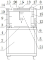
Fig. 1 is a front view of a housing punching device.
FIG. 2 is a schematic diagram of a side view of a housing perforating apparatus.
FIG. 3 is a schematic structural diagram of a support seat in the housing punching apparatus.
In the figure: the machine body 1, a processing table 2, a supporting seat 3, a sliding block 4, a sliding rail 5, a longitudinal screw 6, a limiting seat 7, a first motor 8, a sliding chute 9, a guide post 10, an end cover 11, a rib plate 12, a lifting seat 13, a guide post hole 14, a hydraulic cylinder 15, a transverse screw 16, a shaft seat 17, a sliding seat 18, a clamping plate 19, a guide table 20, an installation seat 21, a bottom plate 22, a second motor 23, a punching chuck 24, a driven gear 25 and a driving gear 26.
Detailed Description
The technical solutions in the embodiments of the present invention will be described clearly and completely with reference to the accompanying drawings in the embodiments of the present invention, and it is obvious that the described embodiments are only some embodiments of the present invention, not all embodiments. Based on the embodiments in the present invention, all other embodiments obtained by a person skilled in the art without creative work belong to the protection scope of the present invention.
Referring to fig. 1-3, in the embodiment of the present invention, a housing punching apparatus comprises a machine body 1, a lifting seat 13 and a mounting seat 21, wherein a processing table 2 is disposed on an upper end surface of the machine body 1, supporting seats 3 are disposed on both sides of the processing table 2, a top processing chute 9 of the supporting seat 3 is disposed, a slider 4 is disposed on a lower end surface of the supporting seat 3, a slide rail 5 is disposed on an upper end surface of the machine body 1, the slide rail 5 is matched with the slider 4, a longitudinal screw 6 is disposed at a bottom of the supporting seat 3 and is in threaded fit with the supporting seat 3, limiting seats 7 are disposed on both ends of the slide rail 5, the limiting seats 7 are matched with shaft ends on both sides of the longitudinal screw 6 through bearings and are connected with the machine body 1 through bolts, so that the supporting seat 3 is guided and supported by matching with the slider 4 through two sets of parallel slide rails 5, and the longitudinal screw 6 drives the, and is easy to assemble and disassemble, the said lifting seat 13 is set on the top of the supporting seat 3, and both ends of the lifting seat 13 cooperate with the inner chute 9 of the supporting seat 3, and set up the end cap 11 on the top of the supporting seat 3, and set up the guide pillar 10 in the chute 9, the ladder shaft end of both ends of the guide pillar 10 cooperates with bottom surface of the end cap 11 and chute 9, process the guide pillar hole 14 on both ends of the lifting seat 13 at the same time, and cooperate with the guide pillar 10, set up the fluid cylinder 15 in the inboard of the supporting seat 3, the shaft end of the fluid cylinder 15 is connected with lifting seat 13 whorl, so the chute 9 cooperates with guide pillar 10, guide the lifting seat 13, improve the stability of the lifting seat 13, can drive the lifting seat 13 to go up and down vertically along the guide pillar 10 by the fluid cylinder 15, feed more accurately, the processing efficiency is higher, improve the product quality effectively, the said mount pad 21 is set up and down the, axle seats 17 are arranged at two ends of a transverse screw 16 and are connected with the upper end face of a lifting seat 13 through bolts, meanwhile, a sliding seat 18 is arranged on the outer side of the transverse screw 16 and is in threaded fit with the transverse screw 16, clamping plates 19 are arranged on the end faces of two sides of the sliding seat 18, guide platforms 20 are machined on the end faces of two sides of the lifting seat 13 and are matched with the clamping plates 19, the bottom ends of the clamping plates 19 are connected with the top end of an installation seat 21 through bolts, the installation seat 21 is guided and supported through the matching of the clamping plates 19 and the guide platforms 20, the transverse screw 16 rotates and drives the sliding seat 18 to slide transversely, and the installation seat 21 can be driven to slide transversely through the clamping plates 19, so that the transverse punching position is adjusted, the machining efficiency is effectively improved, and.
The support seat 3 is of a T-shaped structure, and rib plates 12 are machined on two sides of a straight rod part at the top and are connected with a cross rod part.
The overhanging shaft end of the front side of the longitudinal screw 6 is provided with a driven gear 25, the front side of the upper end surface of the machine body 1 is provided with a first motor 8, and the shaft end of the first motor 8 is provided with a driving gear 26 and is meshed with the driven gear 25.
The first motors 8 are divided into two groups, one group corresponds to the longitudinal screw 6, and the other group is arranged on the right side of the upper end face of the lifting seat 13 and is connected with the outer extending shaft end on the right side of the transverse screw 16 through a coupler.
The utility model discloses a theory of operation is: during the use, select the punching knife in corresponding aperture to in packing into punching knife chuck 24, drive respectively through first motor 8 and indulge screw rod 6 and horizontal screw rod 16 and rotate, can adjust the position of mount pad 21, and drive lift seat 13 by pneumatic cylinder 15 and follow guide pillar 10 vertical lift, drive the punching knife by second motor 23 simultaneously and punch, punch labour saving and time saving more, machining efficiency is higher, and the precision is higher, improves product quality effectively.
Although the present invention has been described in detail with reference to the foregoing embodiments, it will be apparent to those skilled in the art that modifications may be made to the embodiments or portions thereof without departing from the spirit and scope of the invention.
Claims (5)
1. A shell punching device comprises a machine body, a lifting seat and a mounting seat, and is characterized in that a processing table is arranged on the upper end face of the machine body, supporting seats are arranged on two sides of the processing table, sliding grooves are formed in the tops of the supporting seats, sliding blocks are arranged on the lower end faces of the supporting seats, sliding rails are arranged on the upper end face of the machine body and matched with the sliding blocks, longitudinal screws are arranged at the bottoms of the supporting seats and matched with the supporting seats in a threaded mode, limiting seats are arranged on two ends of each sliding rail and matched with shaft ends on two sides of each longitudinal screw through bearings and connected with the machine body through bolts, the lifting seat is arranged on the top of the supporting seat, two ends of the lifting seat are matched with the sliding grooves in the supporting seats, end covers are arranged at the top ends of the supporting seats, guide pillars are arranged in the sliding grooves, stepped shaft ends at two ends of each guide pillar are matched with the end, the lifting seat is arranged below the lifting seat, a transverse screw is arranged above the lifting seat, shaft seats are arranged at two ends of the transverse screw and are in bolted connection with the upper end face of the lifting seat, a sliding seat is arranged outside the transverse screw and is in threaded fit with the transverse screw, clamping plates are arranged on the end faces of two sides of the sliding seat, guide platforms are machined on the end faces of two sides of the lifting seat and are matched with the clamping plates, and the bottom ends of the clamping plates are in bolted connection with the top end of the mounting seat.
2. The shell punching device according to claim 1, wherein the mounting base is of a U-shaped structure, a bottom plate is arranged at the bottom end of the mounting base, a second motor is arranged on the upper end face of the bottom plate, and a punching chuck is arranged at the outer extending shaft end of the second motor, so that the punching knife is arranged in the punching chuck, the punching knife can be driven by the second motor to punch, and punching is more time-saving and labor-saving.
3. The shell perforating apparatus of claim 1 wherein the support base is a T-shaped structure and ribs are machined on both sides of the top straight bar section and connected to the cross bar section.
4. The shell drilling device as claimed in claim 1, wherein the extended shaft end of the front side of the longitudinal screw is provided with a driven gear, the front side of the upper end surface of the machine body is provided with a first motor, and the shaft end of the first motor is provided with a driving gear and meshed with the driven gear.
5. The shell punching device according to claim 4, wherein the first motors are arranged in two groups, one group corresponds to the longitudinal screw rod, and the other group is arranged on the right side of the upper end face of the lifting seat and is connected with the outward extending shaft ends on the right side of the transverse screw rod through a coupling.
Priority Applications (1)
| Application Number | Priority Date | Filing Date | Title |
|---|---|---|---|
| CN201921105725.1U CN210648612U (en) | 2019-07-16 | 2019-07-16 | Shell drilling equipment |
Applications Claiming Priority (1)
| Application Number | Priority Date | Filing Date | Title |
|---|---|---|---|
| CN201921105725.1U CN210648612U (en) | 2019-07-16 | 2019-07-16 | Shell drilling equipment |
Publications (1)
| Publication Number | Publication Date |
|---|---|
| CN210648612U true CN210648612U (en) | 2020-06-02 |
Family
ID=70836634
Family Applications (1)
| Application Number | Title | Priority Date | Filing Date |
|---|---|---|---|
| CN201921105725.1U Expired - Fee Related CN210648612U (en) | 2019-07-16 | 2019-07-16 | Shell drilling equipment |
Country Status (1)
| Country | Link |
|---|---|
| CN (1) | CN210648612U (en) |
-
2019
- 2019-07-16 CN CN201921105725.1U patent/CN210648612U/en not_active Expired - Fee Related
Similar Documents
| Publication | Publication Date | Title |
|---|---|---|
| CN202655708U (en) | Gantry type planing machine | |
| CN201432132Y (en) | Vertical and horizontal dual-purpose numerical control milling machine | |
| CN209830864U (en) | Tubular product cutting perforating device is used in bicycle production | |
| CN206622510U (en) | A kind of numerical control press workbench | |
| CN108503206A (en) | A kind of glass cutting machine facilitating fastening glass panels material | |
| CN210025547U (en) | Circuit board punching device | |
| CN201619199U (en) | Gate type hydraulic large cutting machine | |
| CN206702592U (en) | Machine tooling feed drive unit | |
| CN217860086U (en) | But cutting device is used in hull steel processing of fixed length cutting | |
| CN210967135U (en) | Power head lifting mechanism of gantry movable type numerical control milling machine | |
| CN210549518U (en) | Cutting device is used in production of environmental protection new material | |
| CN203696014U (en) | Chord-specific drilling machine | |
| CN214722196U (en) | Movable beam type numerical control planer type milling machine | |
| CN114453676A (en) | Gear tooth form positioning and milling device for production of planetary gear speed reducer | |
| CN221454390U (en) | Synchronous drilling device for aluminum die | |
| CN213888360U (en) | A kind of magnesium alloy thick plate milling device | |
| CN202639443U (en) | Machine tool special for table top processing of closed press machine workbench | |
| CN206810964U (en) | Wide sheet automatic moulding machine | |
| CN213470291U (en) | A thin-walled aluminum frame clamping assembly based on semi-automatic clamping and alignment technology | |
| CN102717131B (en) | Open presser workbench surface processing special machine tool | |
| CN2106675U (en) | Edge milling machine | |
| CN217251941U (en) | Power device of buckle die | |
| CN208866426U (en) | Multi-axle multi-station drilling machine | |
| CN215145271U (en) | Novel cutting is used in mould steel processing device | |
| CN214651856U (en) | Feeding device for paper bowl and bowl cover blanks |
Legal Events
| Date | Code | Title | Description |
|---|---|---|---|
| GR01 | Patent grant | ||
| GR01 | Patent grant | ||
| CF01 | Termination of patent right due to non-payment of annual fee | ||
| CF01 | Termination of patent right due to non-payment of annual fee |
Granted publication date: 20200602 Termination date: 20210716 |