CN210646452U - Energy-saving constant temperature and humidity case - Google Patents
Energy-saving constant temperature and humidity case Download PDFInfo
- Publication number
- CN210646452U CN210646452U CN201921551608.8U CN201921551608U CN210646452U CN 210646452 U CN210646452 U CN 210646452U CN 201921551608 U CN201921551608 U CN 201921551608U CN 210646452 U CN210646452 U CN 210646452U
- Authority
- CN
- China
- Prior art keywords
- door
- box
- inner cavity
- constant temperature
- supporting shell
- Prior art date
- Legal status (The legal status is an assumption and is not a legal conclusion. Google has not performed a legal analysis and makes no representation as to the accuracy of the status listed.)
- Expired - Fee Related
Links
Images



Landscapes
- Air Humidification (AREA)
Abstract
The utility model discloses an energy-saving constant temperature and humidity box in the technical field of constant temperature and humidity boxes, which comprises a supporting bottom plate, wherein the top of the supporting bottom plate is provided with a supporting shell, the upper part of the front wall of the supporting shell is provided with a box door, the right end of the front side wall of the box door is provided with a door handle, the middle part of the box door is provided with an air exchange door, the middle part of the inner cavity of the supporting shell is provided with a box body, the bottom of the inner cavity of the box body is provided with two groups of electric heating blocks, the top level of the two groups of electric heating blocks is provided with a heat conduction clapboard, the top of the box body is provided with a humidifying spray head, the water vapor passing through a heat preservation pipe is properly heated up through hot air, the temperature of the water vapor entering the inner cavity of the box body is close to the temperature, reduce the electric quantity that the electric heating piece continuously operated consumed, be favorable to the utility model discloses a popularization.
Description
Technical Field
The utility model relates to a constant temperature and humidity case technical field specifically is an energy-saving constant temperature and humidity case.
Background
The constant temperature and humidity test box is also called a constant temperature and humidity tester, a constant temperature and humidity test box, a programmable humid heat alternating test box, a constant temperature machine or an energy-saving constant temperature and humidity box, is used for detecting the performance of materials in various environments and testing the heat resistance, cold resistance, dry resistance and humidity resistance of various materials.
An energy-saving constant temperature and humidity box mainly plays a role in providing an environment with constant temperature and humidity, and is essential detection equipment for testing in the research and development and test verification processes of electronic elements. It is suitable for the quality detection of products such as electronics, electrical appliances, mobile phones, communication, instruments, vehicles, plastic products, metal, food, chemistry, building materials, medical treatment, aerospace and the like.
Current constant temperature and humidity case reaches the purpose of constant temperature and humidity mostly through heating and humidification to the inside continuous of box, but current constant temperature and humidity case structure is comparatively simple, and the heat scatters and disappears very fast, needs continuous supplementary heat, causes a large amount of energy resource consumptions to the in-process of carrying out the humidification to the box inside, steam produces great influence to the inside temperature of box easily, makes the incasement temperature float fast, and the influence detects.
Based on this, the utility model designs an energy-saving constant temperature and humidity case to solve above-mentioned problem.
SUMMERY OF THE UTILITY MODEL
The utility model aims at providing an energy-saving constant temperature and humidity case, with solve the current constant temperature and humidity case that proposes among the above-mentioned background and mostly reach the purpose of constant temperature and humidity through heating and humidification inside the box continuous, but current constant temperature and humidity case structure is comparatively simple, the heat scatters and disappears very fast, need continuous supplementary heat, cause a large amount of energy resource consumptions, and to the inside in-process that carries out the humidification of box, steam produces great influence to the inside temperature of box easily, make the internal temperature of box float fast, influence the problem that detects.
In order to achieve the above object, the utility model provides a following technical scheme: an energy-saving constant temperature and humidity box comprises a supporting bottom plate, wherein a supporting shell is arranged at the top of the supporting bottom plate, a box door is arranged at the upper part of the front wall of the supporting shell, a door handle is arranged at the right end of the front side wall of the box door, a ventilation door is arranged in the middle of the box door, a box body is arranged in the middle of an inner cavity of the supporting shell, two groups of electric heating blocks are arranged at the bottom of the inner cavity of the box body, a heat conduction partition plate is horizontally arranged at the top of the two groups of electric heating blocks, a humidifying spray nozzle is arranged at the top of the box body, a heat insulation layer is wrapped outside the box body, a humidifying bin is arranged at the lower end of the inner cavity of the supporting shell, a steam humidifier is arranged in the middle of the inner cavity of the humidifying bin, a liquid inlet is communicated with the lower, the upper end of the heat preservation pipe is communicated with the humidifying spray head, and the surfaces of the supporting shells on the outer sides of the two groups of heat preservation pipes are provided with hot air blowers.
Preferably, the ventilation door includes door frame, slide rail, jube and dodge gate, the door frame is embedded to be set up in the inner chamber of chamber door, the inner chamber of door frame is provided with the slide rail, equidistant distribution is provided with the jube between the inner chamber of door frame, the front surface of slide rail cup joints and is provided with the dodge gate.
Preferably, the middle part of insulating tube includes three vertical pipes of group, three groups the upper and lower both ends of vertical pipe are assembled each other and are accepted the return bend respectively, the body of insulating tube is the good metal material of heat conductivity.
Preferably, the box door is movably connected with the supporting shell through a louver, and the inner side wall of the box door is tightly closed with the supporting shell through a sealing ring.
Preferably, the support housing portion corresponding to the hot air blower is provided with a communication port.
Compared with the prior art, the beneficial effects of the utility model are that: the utility model discloses place the article that will detect in the inner chamber of box, through control electrical heating piece ohmic heating, the electrical heating piece generates heat and heats the heat conduction baffle, thereby reach the control to box inner chamber temperature, pour water into the inner chamber in humidification storehouse from the inlet, through control steam humidifier operation, carry out steam atomization with liquid water, steam reachs the humidification shower nozzle through the insulating tube, two sets of hot-blast blower ohmic operation this moment, will suitably heat up through the steam of insulating tube through hot-blast, make the steam that gets into box inner chamber close with the temperature of box inner chamber temperature, reduce the change that steam brought box inner chamber temperature, the outside parcel of box is provided with the insulating layer, can effectively slow down the thermal loss of box, reduce the electric quantity that the electrical heating piece continuously runs and consume, be favorable to the utility model discloses a popularization.
Drawings
In order to more clearly illustrate the technical solutions of the embodiments of the present invention, the drawings used in the description of the embodiments will be briefly introduced below, and it is obvious that the drawings in the following description are only some embodiments of the present invention, and it is obvious for those skilled in the art that other drawings can be obtained according to these drawings without creative efforts.
FIG. 1 is a schematic view of the external structure of the present invention;
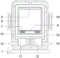
FIG. 2 is a schematic view of the internal structure of the present invention;
FIG. 3 is a schematic view of the structure of the heat preservation pipe of the present invention;
fig. 4 is a top view of the supporting rod structure of the present invention.
In the drawings, the components represented by the respective reference numerals are listed below:
1-supporting bottom plate, 2-supporting shell, 3-box door, 4-door handle, 5-ventilation door, 501-door frame, 502-slide rail, 503-partition bar, 504-movable door, 6-box body, 7-electric heating block, 8-heat-conducting partition plate, 9-humidifying spray head, 10-heat-insulating layer, 11-humidifying bin, 12-steam humidifier, 13-liquid inlet, 14-liquid outlet, 15-heat-insulating pipe, 151-vertical pipe, 152-bent pipe and 16-hot air blower.
Detailed Description
The technical solutions in the embodiments of the present invention will be described clearly and completely with reference to the accompanying drawings in the embodiments of the present invention, and it is obvious that the described embodiments are only some embodiments of the present invention, not all embodiments. Based on the embodiments of the present invention, all other embodiments obtained by a person of ordinary skill in the art without creative efforts belong to the protection scope of the present invention.
Referring to fig. 1-4, the present invention provides a technical solution: an energy-saving constant temperature and humidity box comprises a supporting base plate 1, a supporting shell 2 is arranged on the top of the supporting base plate 1, a box door 3 is arranged on the upper portion of the front wall of the supporting shell 2, a door handle 4 is arranged at the right end of the front side wall of the box door 3, a ventilation door 5 is arranged in the middle of the box door 3, a box body 6 is arranged in the middle of an inner cavity of the supporting shell 2, two groups of electric heating blocks 7 are arranged at the bottom of the inner cavity of the box body 6, a heat conduction partition plate 8 is horizontally arranged at the top of the two groups of electric heating blocks 7, a humidifying nozzle 9 is arranged at the top of the box body 6, a heat insulation layer 10 is wrapped outside the box body 6, a humidifying bin 11 is arranged at the lower end of the inner cavity of the supporting shell 2, a steam humidifier 12 is arranged in the middle of the inner cavity of the humidifying bin 11, a, the upper ends of the heat preservation pipes 15 are communicated with the humidifying nozzles 9, and the surfaces of the supporting shells 2 on the outer sides of the two groups of heat preservation pipes 15 are provided with hot air blowers 16.
The ventilation door 5 comprises a door frame 501, a slide rail 502, a partition 503 and a movable door 504, the door frame 501 is embedded in the inner cavity of the door 3, the slide rail 502 is arranged in the inner cavity of the door frame 501, the partition 503 is arranged between the inner cavities of the door frame 501 at equal intervals, and the movable door 504 is sleeved on the front surface of the slide rail 502. Secondly, the middle part of insulating tube 15 includes three vertical pipes 151, and the upper and lower both ends of three vertical pipes 151 of group are assembled each other and are accepted the return bend 152 respectively, and the body of insulating tube 15 is the good metal material of heat conductivity. Furthermore, the box door 3 is movably connected with the supporting shell 2 through a louver, and the inner side wall of the box door 3 is tightly closed with the supporting shell 2 through a sealing ring. Finally, the portion of the support case 2 corresponding to the hot air blower 16 is provided with a communication port.
One specific application of this embodiment is: the box door 3 is opened, the object to be detected is placed in the inner cavity of the box body 6, the external power supply is connected through the control switch, so that the electric heating block 7 is electrified and heated, the electric heating block 7 generates heat to heat the heat conduction partition plate 8, thereby achieving the control of the temperature of the inner cavity of the box body 6, injecting water into the inner cavity of the humidifying bin 11 from the liquid inlet 13, the operation of the steam humidifier 12 is controlled to atomize the liquid water by steam, the water vapor reaches the humidifying spray head 9 through the heat preservation pipe 15, at the moment, two groups of hot air blowers 16 are electrified to operate, the water vapor passing through the heat preservation pipe 15 is properly heated up through hot air, so that the temperature of the water vapor entering the inner cavity of the box body 6 is close to the temperature of the inner cavity of the box body 6, the change of the water vapor to the temperature of the inner cavity of the box body 6 is reduced, the outer side of the box body 6 is wrapped with a heat insulation layer 10, the heat loss of the box body 6 can be effectively reduced, and the electric quantity consumed by the continuous operation of the electric heating block 7 is reduced.
In the description herein, references to the description of "one embodiment," "an example," "a specific example," etc., mean that a particular feature, structure, material, or characteristic described in connection with the embodiment or example is included in at least one embodiment or example of the invention. In this specification, the schematic representations of the terms used above do not necessarily refer to the same embodiment or example. Furthermore, the particular features, structures, materials, or characteristics described may be combined in any suitable manner in any one or more embodiments or examples.
The preferred embodiments of the present invention disclosed above are intended only to help illustrate the present invention. The preferred embodiments are not intended to be exhaustive or to limit the invention to the precise embodiments disclosed. Obviously, many modifications and variations are possible in light of the above teaching. The embodiments were chosen and described in order to best explain the principles of the invention and its practical applications, to thereby enable others skilled in the art to best understand the invention for and utilize the invention. The present invention is limited only by the claims and their full scope and equivalents.
Claims (5)
1. The utility model provides an energy-saving constant temperature and humidity case, includes supporting baseplate (1), its characterized in that: the top of the supporting base plate (1) is provided with a supporting shell (2), the upper part of the front wall of the supporting shell (2) is provided with a box door (3), the right end of the front side wall of the box door (3) is provided with a door handle (4), the middle part of the box door (3) is provided with a ventilation door (5), the middle part of the inner cavity of the supporting shell (2) is provided with a box body (6), the bottom of the inner cavity of the box body (6) is provided with two groups of electric heating blocks (7), the top of the two groups of electric heating blocks (7) is horizontally provided with a heat conducting partition plate (8), the top of the box body (6) is provided with a humidifying nozzle (9), the outer side of the box body (6) is wrapped with a heat insulation layer (10), the lower end of the inner cavity of the supporting shell (2) is provided with a humidifying bin (11), the middle part of the inner cavity, the utility model discloses a humidification shower nozzle, including humidification storehouse (11), the right side wall lower extreme intercommunication in humidification storehouse (11) is provided with leakage fluid dram (14), both ends lateral wall intercommunication is provided with insulating tube (15) about humidification storehouse (11), the upper end and the humidification shower nozzle (9) of insulating tube (15) communicate each other, and two sets of supporting shell (2) surface in the insulating tube (15) outside all is provided with hot-blast blower (16).
2. The energy-saving constant temperature and humidity box of claim 1, characterized in that: the ventilation door (5) comprises a door frame (501), a sliding rail (502), a partition (503) and a movable door (504), wherein the door frame (501) is embedded in an inner cavity of the door (3), the sliding rail (502) is arranged in the inner cavity of the door frame (501), the partition (503) is arranged between the inner cavities of the door frame (501) in an equidistant mode, and the movable door (504) is sleeved on the front surface of the sliding rail (502).
3. The energy-saving constant temperature and humidity box of claim 1, characterized in that: the middle part of insulating tube (15) includes three vertical pipes (151), three groups the upper and lower both ends of vertical pipe (151) are assembled each other and have been accepted return bend (152) respectively, the body of insulating tube (15) is the good metal material of heat conductivity.
4. The energy-saving constant temperature and humidity box of claim 1, characterized in that: the box door (3) is movably connected with the supporting shell (2) through a louver, and the inner side wall of the box door (3) is tightly closed with the supporting shell (2) through a sealing ring.
5. The energy-saving constant temperature and humidity box of claim 1, characterized in that: the part of the support shell (2) corresponding to the hot air blower (16) is provided with a communication port.
Priority Applications (1)
| Application Number | Priority Date | Filing Date | Title |
|---|---|---|---|
| CN201921551608.8U CN210646452U (en) | 2019-09-18 | 2019-09-18 | Energy-saving constant temperature and humidity case |
Applications Claiming Priority (1)
| Application Number | Priority Date | Filing Date | Title |
|---|---|---|---|
| CN201921551608.8U CN210646452U (en) | 2019-09-18 | 2019-09-18 | Energy-saving constant temperature and humidity case |
Publications (1)
| Publication Number | Publication Date |
|---|---|
| CN210646452U true CN210646452U (en) | 2020-06-02 |
Family
ID=70833723
Family Applications (1)
| Application Number | Title | Priority Date | Filing Date |
|---|---|---|---|
| CN201921551608.8U Expired - Fee Related CN210646452U (en) | 2019-09-18 | 2019-09-18 | Energy-saving constant temperature and humidity case |
Country Status (1)
| Country | Link |
|---|---|
| CN (1) | CN210646452U (en) |
Cited By (2)
| Publication number | Priority date | Publication date | Assignee | Title |
|---|---|---|---|---|
| CN111997421A (en) * | 2020-08-10 | 2020-11-27 | 徐继伟 | Constant-temperature constant-humidity energy-saving bin for 3D printing equipment |
| CN113647323A (en) * | 2021-09-28 | 2021-11-16 | 河北农业大学 | A kind of adjustable plant high-efficiency wet steam emasculation device and wet steam emasculation method |
-
2019
- 2019-09-18 CN CN201921551608.8U patent/CN210646452U/en not_active Expired - Fee Related
Cited By (3)
| Publication number | Priority date | Publication date | Assignee | Title |
|---|---|---|---|---|
| CN111997421A (en) * | 2020-08-10 | 2020-11-27 | 徐继伟 | Constant-temperature constant-humidity energy-saving bin for 3D printing equipment |
| CN113647323A (en) * | 2021-09-28 | 2021-11-16 | 河北农业大学 | A kind of adjustable plant high-efficiency wet steam emasculation device and wet steam emasculation method |
| CN113647323B (en) * | 2021-09-28 | 2023-11-03 | 河北农业大学 | Adjustable plant efficient wet steaming emasculation device and wet steaming emasculation method |
Similar Documents
| Publication | Publication Date | Title |
|---|---|---|
| CN205944811U (en) | External high -efficient semiconductor constant temperature dehumidifier | |
| CN207724548U (en) | A kind of cement constant temperature and humidity standard curing box | |
| CN210999294U (en) | Energy-concerving and environment-protective concrete curing box | |
| CN107570219A (en) | A kind of portable type energy-saving constant-temperature case | |
| CN206037624U (en) | Hot -air oven | |
| CN102492620B (en) | Incubator | |
| CN216499430U (en) | Constant temperature and humidity case convenient to adjust | |
| CN201237286Y (en) | Semiconductor hot-water heating system | |
| CN207123525U (en) | Novel steam ageing oven | |
| CN213304762U (en) | Metal-enclosed switchgear with heat abstractor | |
| CN221897770U (en) | A steam generator with double heating elements | |
| CN210035860U (en) | Intelligent heating heat-preservation water storage tank | |
| CN201024339Y (en) | Clothes drying cabinet | |
| CN207050073U (en) | A kind of warmer with humidification function | |
| CN203687413U (en) | Solar air heating machine | |
| CN206846879U (en) | A kind of ceramic heat electric heater | |
| CN207094734U (en) | A kind of electric heater for possessing drying function | |
| CN201539974U (en) | Inlet pipe connector of electric water heater | |
| CN206019165U (en) | Skin care item vacuum drying oven | |
| CN212778319U (en) | Drying device for incense making | |
| CN203359187U (en) | Resistance heating exhaust container | |
| CN208296312U (en) | A kind of energy-storage type electric heating water heater | |
| CN216081552U (en) | Hygrothermograph verification box | |
| CN209423644U (en) | A constant temperature and humidity cycle test chamber | |
| CN210055747U (en) | Novel energy-saving electric heating thermal insulation cabinet |
Legal Events
| Date | Code | Title | Description |
|---|---|---|---|
| GR01 | Patent grant | ||
| GR01 | Patent grant | ||
| CF01 | Termination of patent right due to non-payment of annual fee | ||
| CF01 | Termination of patent right due to non-payment of annual fee |
Granted publication date: 20200602 Termination date: 20210918 |