SUMMERY OF THE UTILITY MODEL
An object of the utility model is to provide a direct drive formula rotary driving mechanism and around rolling up device aims at solving the middle drive disk assembly and has accumulative assembly error and influence transmission efficiency and stability, and then influences the problem of rolling up efficiency and quality of battery core package.
A direct drive type rotary driving mechanism comprises
The stator assembly is arranged on the inner wall of the shell; and
one end of the driving shaft penetrates through the shell, the other end of the driving shaft extends out of the shell and is connected with an assembling head, and the assembling head is used for installing a winding needle; and a rotor assembly is sleeved outside the shaft section of the driving shaft in the shell, and the stator assembly can drive the rotor assembly to rotate after being electrified.
In one embodiment, the housing is further provided with a plug wire connector, and the plug wire connector is electrically connected with the stator assembly.
In one embodiment, the rotor assembly further comprises a shaft sleeve, the shaft sleeve is sleeved on the driving shaft, and the rotor assembly is arranged outside the shaft sleeve.
In one embodiment, the outer circumferential wall of the driving shaft is provided with a first tooth structure, and the inner circumferential wall of the shaft sleeve is provided with a second tooth structure, wherein the first tooth structure is meshed with the second tooth structure.
In one embodiment, the rotor assembly further comprises a transmission sleeve, the transmission sleeve is sleeved outside the shaft sleeve, and the rotor assembly is locked and fixed with the transmission sleeve through screws.
In one embodiment, the device further comprises a bearing, wherein the bearing is arranged between the transmission sleeve and the inner wall of the shell.
In one embodiment, the device further comprises an encoder, wherein the encoder is arranged at the end part of the transmission sleeve.
In one embodiment, the device further comprises a positioning shaft sleeve, wherein the positioning shaft sleeve is sleeved outside the driving shaft and is abutted against the side wall of the shell.
In one embodiment, the assembly head further comprises a guide member, wherein the guide member is sleeved at one end of the driving shaft close to the assembly head, so that the driving shaft can move back and forth relative to the guide member.
A winding device comprising a direct drive rotary drive mechanism as described above.
Implement the embodiment of the utility model provides a, will have following beneficial effect:
when the direct-drive rotary driving mechanism of the scheme is used for driving the winding needle to perform winding operation, the winding needle can be connected to the assembling head firstly, and the winding needle and the assembling head are kept relatively static; then, electrifying the stator assembly, the stator assembly can generate an electromagnetic field, and the stator assembly drives the rotor assembly to start rotating under the action of the electromagnetic force; because the rotor assembly is installed on the drive shaft, therefore the drive shaft can be synchronous along with the rotor assembly and rotate together, finally drive through the installation head and roll up the needle and rotate, can carry out the operation of taking up a roll. Compare in traditional drive mode, this scheme has saved middle transmission parts such as gear pair, belt pulley, but the electromagnetic drive through stator module and rotor subassembly directly drives the drive shaft and drives the book needle rotation, therefore can not have accumulative assembly error, and then can not influence transmission efficiency and stability, can effectively guarantee winding efficiency and shaping quality of battery core package.
Drawings
In order to more clearly illustrate the embodiments of the present invention or the technical solutions in the prior art, the drawings used in the description of the embodiments or the prior art will be briefly described below, it is obvious that the drawings in the following description are only some embodiments of the present invention, and for those skilled in the art, other drawings can be obtained according to these drawings without creative efforts.
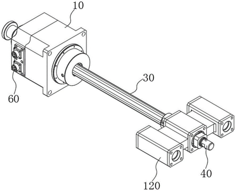
Wherein: 10. the motor comprises a shell, 20, a stator assembly, 30, a driving shaft, 40, an assembling head, 50, a rotor assembly, 60, a plug wire connector, 70, a shaft sleeve, 80, a transmission sleeve, 90, a bearing, 100, an encoder, 110, a positioning shaft sleeve, 120 and a guide piece.
Fig. 1 is a schematic structural diagram of a direct-drive rotary driving mechanism according to an embodiment of the present invention;
FIG. 2 is a schematic top view of the structure of FIG. 1;
FIG. 3 is a schematic cross-sectional view taken along line A-A of FIG. 2;
fig. 4 is a partially enlarged structural view at B in fig. 3.
Detailed Description
In order to facilitate understanding of the present invention, the present invention will be described more fully hereinafter with reference to the accompanying drawings. Preferred embodiments of the present invention are shown in the drawings. The invention may, however, be embodied in many different forms and should not be construed as limited to the embodiments set forth herein. Rather, these embodiments are provided so that this disclosure will be thorough and complete.
It will be understood that when an element is referred to as being "secured to" another element, it can be directly on the other element or intervening elements may also be present. When an element is referred to as being "connected" to another element, it can be directly connected to the other element or intervening elements may also be present. The terms "vertical," "horizontal," "left," "right," and the like as used herein are for illustrative purposes only.
Unless defined otherwise, all technical and scientific terms used herein have the same meaning as commonly understood by one of ordinary skill in the art to which this invention belongs. The terminology used in the description of the invention herein is for the purpose of describing particular embodiments only and is not intended to be limiting of the invention. As used herein, the term "and/or" includes any and all combinations of one or more of the associated listed items.
As shown in fig. 1 to fig. 3, a direct-drive rotary driving mechanism is shown for outputting a rotary driving force to drive a winding needle to rotate, so that the winding needle can complete a winding operation.
Specifically, the direct drive rotary drive mechanism includes a housing 10, a stator assembly 20, a rotor assembly 50, and a drive shaft 30. The stator assembly 20 is disposed on an inner wall of the housing 10 and can be kept stationary relative to the housing 10. The mounting mode of the two can be bonding, screw connection, riveting or snap connection and the like.
One end of the driving shaft 30 is arranged through the shell 10, and the other end of the driving shaft extends out of the shell 10 and is connected with an assembling head 40, wherein the assembling head 40 is used for installing a winding needle; the rotor assembly 50 is sleeved outside the shaft section of the driving shaft 30 in the housing 10, and the winding assembly can keep relative static with the driving shaft 30, and the installation mode of the winding assembly and the driving shaft 30 can be bonding, screwing, riveting or buckling connection and fixation. The rotor assembly 50 can be driven to rotate after the stator assembly 20 is powered on.
Implement the embodiment of the utility model provides a, will have following beneficial effect: when the direct-drive rotary driving mechanism of the scheme is used for driving the winding needle to perform winding operation, the winding needle can be firstly connected to the assembly head 40, and the winding needle and the assembly head are kept relatively static; then, the stator assembly 20 is powered on, so that the stator assembly 20 can generate an electromagnetic field, and the stator assembly 20 drives the rotor assembly 50 to start rotating under the action of the electromagnetic force; since the rotor assembly 50 is mounted on the driving shaft 30, the driving shaft 30 can synchronously rotate along with the rotor assembly 50, and finally the winding needle is driven by the mounting head to rotate, so that the winding operation can be performed. Compared with the traditional driving mode, the scheme omits intermediate transmission parts such as a gear pair and a belt pulley, but directly drives the driving shaft 30 to drive the winding needle to rotate through the electromagnetic driving of the stator assembly 20 and the rotor assembly 50, so that the accumulated assembly error can not exist, the transmission efficiency and the stability can not be influenced, and the winding efficiency and the forming quality of the battery core package can be effectively ensured.
It will be appreciated that the stator assembly 20 and the rotor assembly 50 may employ the structure and operation of the stator and rotor of the prior art electric machine, and will not be described in detail herein.
Referring to fig. 1, in order to facilitate the access of electric energy to the stator assembly 20, so that the stator assembly 20 can generate electromagnetic force to drive the rotor assembly 50 to rotate, the housing 10 is further provided with a plug wire connector 60, and the plug wire connector 60 is electrically connected to the stator assembly 20. Therefore, the plug wire connector 60 is convenient to be quickly plugged with a plug of an external power supply, so that the device can obtain electric energy quickly and efficiently.
Alternatively, the wire connectors 60 may be, but are not limited to, two-hole connectors, three-hole connectors, aircraft connectors, or the like.
With reference to fig. 4, in order to ensure that the rotor assembly 50 is firmly mounted to the driving shaft 30, in one embodiment, the apparatus (hereinafter, referred to as a direct-drive rotary driving mechanism) further includes a shaft sleeve 70, the shaft sleeve 70 is sleeved on the driving shaft 30, and the rotor assembly 50 is disposed outside the shaft sleeve 70. Specifically, the rotor assembly 50 may be secured to the outer wall of the sleeve 70 by interference fit, adhesive, or the like. The sleeve 70 needs to be stationary relative to the drive shaft 30 so that the sleeve 70 can transmit rotational power to cause the drive shaft 30 to rotate synchronously with the rotor assembly 50.
Further, the outer circumferential wall of the driving shaft 30 is provided with a first tooth structure, and the inner circumferential wall of the sleeve 70 is provided with a second tooth structure, and the first tooth structure is engaged with the second tooth structure. Therefore, the shaft sleeve 70 and the driving shaft 30 are assembled in a tooth meshing manner, so that the relative sliding phenomenon can be avoided to the maximum extent, and the power transmission efficiency is ensured.
It will be appreciated that the drive shaft 30 is integral with the first tooth structure to form a splined shaft and the sleeve 70 is integral with the second tooth structure to form a splined sleeve 70.
With continued reference to fig. 2 and 4, the device further includes a positioning sleeve 110, wherein the positioning sleeve 110 is sleeved outside the driving shaft 30 and abuts against the side wall of the housing 10. In this way, the positioning shaft sleeve 110 can be installed and positioned on the housing 10, so as to ensure the relative position between the housing 10 and the driving shaft 30 and improve the structural stability of the device.
With continuing reference to fig. 4, in a further embodiment, the apparatus further includes a driving sleeve 80, the driving sleeve 80 is sleeved outside the shaft sleeve 70, and the rotor assembly 50 is locked and fixed with the driving sleeve 80 through a screw. The driving sleeve 80 can serve as a medium for connecting the rotor assembly 50 and the shaft sleeve 70, so that the rotation power of the rotor assembly 50 can be effectively transmitted to the shaft sleeve 70. Specifically, the outer wall surface of the driving sleeve 80 is provided with a stepped portion, and the rotor assembly 50 abuts against the stepped portion and is locked by a screw, so that the radial and axial degrees of freedom of the shaft sleeve 70 can be effectively limited.
In particular, the drive sleeve 80 is a clearance fit with the drive shaft 30. Therefore, the problem that the transmission sleeve 80 is interfered with the driving shaft 30 during assembly to cause abnormal installation due to manufacturing dimension errors is avoided.
With reference to fig. 4, the device further includes a bearing 90, wherein the bearing 90 is disposed between the transmission sleeve 80 and the inner wall of the housing 10, and specifically, the bearings 90 are respectively installed at two ends of the transmission sleeve 80 in the length direction. Therefore, the bearing 90 can be installed to fix the position of the driving sleeve 80, and the driving sleeve 80 can be prevented from friction abrasion with the inner wall of the housing 10 when rotating.
In order to calculate the angle of the winding needle and determine the angular position of the winding needle, the device further comprises an encoder 100, and the encoder 100 is disposed at the end of the driving sleeve 80. Specifically, the encoder 100 is locked to the end of the driving sleeve 80 by a screw and can be rotated in synchronization with the driving sleeve 80, thereby ensuring the counting accuracy.
It should be noted that, when the winding needle works, the winding needle needs to move back and forth, that is, the winding needle moves forward to a preset position so as to clamp the material roll; the backward movement is to release the material roll after the material roll is finished, so that whether the device can accurately move according to the preset path is very important. With this in mind, and with continued reference to fig. 4, in a further embodiment, the device further comprises a guide member 120, said guide member 120 being fitted around an end of said drive shaft 30 adjacent to said mounting head 40, such that said drive shaft 30 can move back and forth relative to said guide member 120. In this way, the guide 120 can guide and position the forward and backward movement of the driving shaft 30 (i.e., the device), and ensure the movement accuracy.
In addition, the present application also provides a winding device, which includes the direct-drive rotary driving mechanism according to any one of the above aspects.
The technical features of the embodiments described above may be arbitrarily combined, and for the sake of brevity, all possible combinations of the technical features in the embodiments described above are not described, but should be considered as being within the scope of the present specification as long as there is no contradiction between the combinations of the technical features.
The above-mentioned embodiments only express several embodiments of the present invention, and the description thereof is more specific and detailed, but not construed as limiting the claims. It should be noted that, for those skilled in the art, without departing from the spirit of the present invention, several variations and modifications can be made, which are within the scope of the present invention. Therefore, the protection scope of the present invention should be subject to the appended claims.