Clamp hole die
Technical Field
The utility model relates to a leaf spring apparatus for producing technical field, concretely relates to clamp mould for hole.
Background
The steel plate spring is an elastic element which is most widely applied in automobile suspensions, and is an elastic beam which is approximately equal in strength and formed by combining a plurality of alloy spring pieces which are equal in width but unequal in length (the thicknesses can be equal or unequal). When the steel plate spring is installed in an automobile suspension and the borne vertical load is positive, each spring piece is stressed and deformed and tends to be arched upwards. At this point, the axle and frame are brought closer together. When the axle and the frame are far away from each other, the positive vertical load and deformation borne by the leaf spring are gradually reduced and sometimes even reversed. In the process of producing the steel plate spring, three working sections of punching and shearing, heat treatment, assembly and the like are required, wherein hot punching is an indispensable working section, and a die for clamping holes is required.
At present, the existing mold for the clamp hole needs to be subjected to five processes, namely, the clamp hole is drilled at the two ends of the second sheet, the conical hoop hole is pressed by the second sheet, the cold cutting angle is arranged at one end of the second sheet, the clamp hole is drilled at one end of the third sheet, and the conical clamp hole is arranged at one end of the third sheet.
SUMMERY OF THE UTILITY MODEL
In order to solve the problem mentioned in the above-mentioned background art, the utility model provides a press from both sides hoop is mould for hole has the production cost background, reduces production processes and accelerates production speed's characteristics.
The utility model discloses a mould for clip hole that realizes like this, including lower bolster and cope match-plate pattern, the top of lower bolster is followed horizontal central line and is had the stripper through hexagon socket head cap screw fixation, and is provided with the stripper gasket between lower bolster and the stripper, the top of lower bolster is located the below of stripper and has the die holder through hexagon socket head cap screw fixation, the top of die holder is inlayed and is equipped with the side stator, and the side stator is fixed through hexagon socket head cap screw and die holder, it is equipped with the lower mould cushion to be located to inlay on the width central line in the die holder, and the top that is located the lower mould cushion in the die holder has the lower mould through hexagon socket cap screw fixation, the top of cope match-plate pattern has the die shank through hexagon socket cap screw fixation, the bottom of cope match-plate pattern has the screw rod through hexagon socket head cap screw fixation, and the other end of screw rod is connected with.
In order to carry on spacingly to the foundry goods, as the utility model relates to a press from both sides hoop is mould is preferred for hole, the rear side that the top of lower bolster is located the stripper has the rear end location through hexagon socket head cap screw fixation.
In order to support the foundry goods, as the utility model relates to a press from both sides hoop is mould is preferred for hole, the top of lower bolster is located the front side of stripper and is fixed with the bracket through hexagon socket head cap screw.
In order to realize supporting the use with other parts, as the utility model discloses a mould is preferred for clamp hole, the length and the width of lower bolster are 500 millimeters and 400 millimeters respectively.
Carry out the punching press to the foundry goods in order to realize that the drift is stable, conduct the utility model relates to a clamp is mould for hole is preferred, the vertical central line of drift and the vertical central line of lower mould are located same straight line.
Use in order to realize that rear end location and bracket cooperate, conduct the utility model relates to a press from both sides hoop is mould for hole is preferred, the equal perpendicular to stripper of extension line of rear end location and bracket.
Compared with the prior art, the beneficial effects of the utility model are that: compared with the prior art, the hot stamping forming is carried out on the clamp holes of the second sheet and the clamp of the third sheet after the long cone is rolled, the working procedures are reduced, the energy consumption is not increased, the working hours are not increased, the overall energy consumption is reduced, the labor cost is reduced, and the production effect is ensured.
Drawings
The accompanying drawings are included to provide a further understanding of the invention, and are incorporated in and constitute a part of this specification, illustrate embodiments of the invention, and together with the description serve to explain the invention and not to limit the invention. In the drawings:
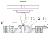
fig. 1 is a schematic front view of the present invention;
FIG. 2 is a schematic side view of the present invention;
fig. 3 is a schematic top view of the present invention.
In the figure, 1, a lower template; 2. a stripper plate; 3. a stripper plate shim; 4. a nut; 5. a screw; 6. mounting a template; 7. a die shank; 8. a punch; 9. side fixing blocks; 10. positioning the rear end; 11. a lower die; 12. a lower die cushion block; 13. a lower die holder; 14. a bracket.
Detailed Description
In order to make the objects, technical solutions and advantages of the present invention more clearly understood, the present invention is further described in detail below with reference to the accompanying drawings and embodiments. It should be understood that the specific embodiments described herein are merely illustrative of the invention and are not intended to limit the invention.
In the description of the present invention, it is to be understood that the terms "length", "width", "upper", "lower", "front", "rear", "left", "right", "vertical", "horizontal", "top", "bottom", "inner", "outer", and the like indicate orientations or positional relationships based on those shown in the drawings, and are merely for convenience of description and simplicity of description, and do not indicate or imply that the device or element being referred to must have a particular orientation, be constructed and operated in a particular orientation, and thus, should not be construed as limiting the present invention. In addition, in the description of the present invention, "a plurality" means two or more unless specifically limited otherwise.
Referring to fig. 1-3, the present invention provides the following technical solutions: the utility model provides a die for clamp hole, including lower bolster 1 and cope match-plate pattern 6, there is stripper 2 at the top of lower bolster 1 along horizontal central line through hexagon socket head cap screw fixation, and be provided with stripper gasket 3 between lower bolster 1 and the stripper 2, there is die holder 13 at the below that the top of lower bolster 1 is located stripper 2 through hexagon socket head cap screw fixation, die holder 13's top is inlayed and is equipped with side stator 9, and side stator 9 is fixed with die holder 13 through hexagon socket head cap screw, it is equipped with lower mould cushion 12 to be located to inlay on the width central line in the die holder 13, and the top that is located lower mould cushion 12 in the die holder 13 has lower mould 11 through hexagon socket cap screw fixation, there is die shank 7 at the top of cope match-plate pattern 6 through hexagon socket head cap screw fixation, there is screw rod 5 at the bottom of cope match-plate pattern 6 through hexagon socket head cap screw fixation, and the other end of screw rod 5 is.
In the scheme of the embodiment: when the device is used, the punch 8 punches downwards to perform hot stamping forming on a casting to be processed, and the device performs hot stamping forming on the clamp holes of the second sheet and the clamp of the third sheet after the long cone is rolled.
Specifically, the top of the lower template 1 is positioned at the rear side of the stripper plate 2, and a rear end positioning 10 is fixed on the top of the lower template through a socket head cap screw.
In this embodiment: the rear end location 10 acts as a stop for the strip process casting.
Specifically, a bracket 14 is fixed on the top of the lower template 1 at the front side of the stripper plate 2 through a socket head cap screw.
In this embodiment: the carriage 14 serves as a support for the casting to be machined.
Specifically, the length and the width of the lower template 1 are respectively 500 mm and 400 mm.
In this embodiment: so that the device can be matched with other components.
Specifically, the vertical center line of the punch 8 and the vertical center line of the lower die 11 are located on the same straight line.
In this embodiment: so that the punch 8 stably carries out hot punching on the belt processing casting without accidental dislocation.
Specifically, the extension lines of the rear end positioning 10 and the bracket 14 are perpendicular to the discharging plate 2.
In this embodiment: the rear end retainer 10 can be made to engage the carriage 14 to allow stable inward movement of the casting to be processed for hot stamping.
The utility model discloses a theory of operation and use flow: can push into the device through bracket 14 will treat the processing foundry goods in, treat that the processing foundry goods can be located lower mould 11, drift 8 moves down, treat the processing foundry goods and carry out the hot punching, carry out the hot punching shaping with the clamp hole of second piece and the clamp of third piece after the long awl calendering, compare with prior art, reduced the process, do not increase the energy consumption, also do not increase man-hour for whole energy consumption reduces, and the cost of labor obtains reducing, has accelerated production speed.
The above description is only a preferred embodiment of the present invention, and is not intended to limit the present invention in other forms, and any person skilled in the art may use the above-mentioned technical contents to change or modify the equivalent embodiment into equivalent changes and apply to other fields, but any simple modification, equivalent change and modification made to the above embodiments according to the technical matters of the present invention will still fall within the protection scope of the technical solution of the present invention.