CN210614802U - Armature punching sheet compound die - Google Patents

Armature punching sheet compound die Download PDF

Info

Publication number
CN210614802U
CN210614802U CN201921649084.6U CN201921649084U CN210614802U CN 210614802 U CN210614802 U CN 210614802U CN 201921649084 U CN201921649084 U CN 201921649084U CN 210614802 U CN210614802 U CN 210614802U
Authority
CN
China
Prior art keywords
die
plate
punch
fixing plate
bolt
Prior art date
Legal status (The legal status is an assumption and is not a legal conclusion. Google has not performed a legal analysis and makes no representation as to the accuracy of the status listed.)
Active
Application number
CN201921649084.6U
Other languages
Chinese (zh)
Inventor
骆科旭
Current Assignee (The listed assignees may be inaccurate. Google has not performed a legal analysis and makes no representation or warranty as to the accuracy of the list.)
Shijiazhuang Jiake Electromechanical Technology Co ltd
Original Assignee
Guiyang Changshunxing Technology Co Ltd
Priority date (The priority date is an assumption and is not a legal conclusion. Google has not performed a legal analysis and makes no representation as to the accuracy of the date listed.)
Filing date
Publication date
Application filed by Guiyang Changshunxing Technology Co Ltd filed Critical Guiyang Changshunxing Technology Co Ltd
Priority to CN201921649084.6U priority Critical patent/CN210614802U/en
Application granted granted Critical
Publication of CN210614802U publication Critical patent/CN210614802U/en
Active legal-status Critical Current
Anticipated expiration legal-status Critical

Links

Images

Landscapes

  • Perforating, Stamping-Out Or Severing By Means Other Than Cutting (AREA)

Abstract

本实用新型公开了一种电枢冲片复合模,包括上模部分和下模部分,上模部分包括从上到下依次设置的模柄、上模板、垫板、凸模固定板、凹模,上模板、垫板、凸模固定板以及凹模通过第二螺栓紧固,上模板内设置有第一退料板,垫板内设置有退料杆,退料杆端头延伸至凹模内,凸模固定板内固定有凸模,凹模内设置有打料器;下模部分包括从下到上依次设置的底板、凸凹模固定板、第二退料板,底板和凸凹模固定板通过第三螺栓紧固,凸凹模固定板和第二退料板通过第四螺栓紧固,凸凹模固定板内固定有凸凹模;上模板和所述底板之间设置有用于调节上模板和底板之间距离的导柱。本实用新型减低操作工人的劳动强度,减少操作工人,提高生产效率。
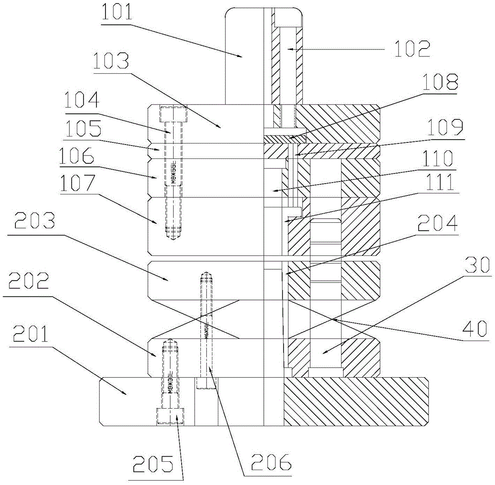
Figure 201921649084

The utility model discloses an armature punching composite die, which comprises an upper die part and a lower die part. The upper die part comprises a die handle, an upper die plate, a backing plate, a punch fixing plate and a concave die which are arranged in sequence from top to bottom. , the upper template, the backing plate, the punch fixing plate and the die are fastened by the second bolts, the upper template is provided with a first return plate, the back plate is provided with a return rod, and the end of the return rod extends to the die Inside, the punch fixing plate is fixed with a punch, and the female die is provided with a feeder; the lower die part includes a bottom plate, a convex and concave die fixing plate, a second ejection plate, and the bottom plate and the convex and concave die are fixed in sequence from bottom to top. The plate is fastened by the third bolt, the male and female mold fixing plate and the second stripping plate are fastened by the fourth bolt, and the male and female mold fixing plate is fixed with a male and female mold; Guide posts for the distance between the base plates. The utility model reduces the labor intensity of the operator, reduces the operator, and improves the production efficiency.

Figure 201921649084

Description

Armature punching sheet compound die
Technical Field
The utility model relates to an armature towards piece mould technical field, concretely relates to armature towards piece compound die.
Background
With the increasingly fierce competition of the punching industry, many punching processing enterprises have to spend great efforts on production management, die cost and automatic production to improve, so as to reduce the production cost and improve the market competitiveness, automatic punching technologies are adopted in many times, and in order to ensure automatic punching, after the existing blanking single-punch die is used for punching, sometimes the punching is adhered to the upper die part, the punching cannot be automatically blanked, and manual taking is needed.
SUMMERY OF THE UTILITY MODEL
An object of the utility model is to provide a reduce operation workman's intensity of labour, reduce operation workman, improve production efficiency's armature towards piece compound die.
In order to further realize the above purpose, the utility model adopts the following technical scheme: an armature punching sheet compound die comprises an upper die part and a lower die part matched with the upper die part, wherein the upper die part comprises a die shank, an upper die plate, a backing plate, a male die fixing plate and a female die which are sequentially arranged from top to bottom, the die shank is fixed at the central position of the upper end surface of the upper die plate through a first bolt, the upper die plate, the backing plate, the male die fixing plate and the female die are fastened through a second bolt, a first stripper plate is arranged in the upper die plate, a stripper rod is arranged in the backing plate, the end of the stripper rod extends into the female die, a male die is fixed in the male die fixing plate, and a feeder is arranged in the female die; the lower die part comprises a bottom plate, a punch-die fixing plate and a second stripper plate which are sequentially arranged from bottom to top, the bottom plate and the punch-die fixing plate are fastened through a third bolt, the punch-die fixing plate and the second stripper plate are fastened through a fourth bolt, and a punch-die is fixed in the punch-die fixing plate; and a guide pillar for adjusting the distance between the upper template and the bottom plate is arranged between the upper template and the bottom plate, and the bottom end of the guide pillar is fixed on the punch-die fixing plate.
The utility model relates to an in the embodiment, be provided with rubber between second material returned board and the punch-die fixed plate.
Compared with the prior art, the utility model discloses following beneficial effect has: the utility model discloses a guide pillar up-and-down motion drives mould part and lower mould part and mutually supports and process the punching sheet, and the blanking is participated in the blade contact of the die of die in the mould part and the blade of the punch-die in the lower mould part in the die stamping process and the punching, accomplishes when the punching press, goes up mould part and lower mould part and parts back separately, will withdraw from the back towards the piece through first material returned board and second material returned board, if glue at last mould part towards the piece, then will beat down towards the piece by the knockout. The utility model discloses reduce operation workman's intensity of labour, reduce operation workman, improve production efficiency.
Drawings
In order to more clearly illustrate the technical solution of the present invention, the drawings needed for the description of the embodiments or the prior art will be briefly described below, and it is obvious that the drawings in the following description are only some embodiments of the present invention, and it is obvious for those skilled in the art that other drawings can be obtained according to the drawings without creative efforts.
Fig. 1 is a schematic structural diagram of the armature punching sheet compound die of the present invention.
Reference numerals: 101-die shank, 102-first bolt, 103-upper die plate, 104-second bolt, 105-backing plate, 106-punch retainer, 107-die, 108-first stripper plate, 109-stripper rod, 110-punch, 111-beater, 201-bottom plate, 202-punch-die retainer, 203-second stripper plate, 204-punch-die, 205-third bolt, 206-fourth bolt, 30-guide post, 40-rubber.
Detailed Description
The technical solutions in the embodiments of the present invention will be described clearly and completely with reference to the accompanying drawings in the embodiments of the present invention, and it is obvious that the described embodiments are only some embodiments of the present invention, not all embodiments. Based on the embodiments of the present invention, all other embodiments obtained by a person of ordinary skill in the art without creative efforts belong to the protection scope of the present invention.
The embodiment of the utility model provides an armature punching sheet compound die, as shown in fig. 1, including last mould part and with the lower mould part of going up mould part looks adaptation, go up the mould part including from the top down die shank 101, cope match-plate pattern 103, backing plate 105, punch plate 106, die 107 that set gradually, die shank 101 is fixed at cope match-plate pattern 103 up end position between two parties through first bolt 102, cope match-plate pattern 103, backing plate 105, punch plate 106 and die 107 are fastened through second bolt 104, be provided with first stripper 108 in the cope match-plate pattern 103, be provided with stripper rod 109 in the backing plate 105, stripper rod 109 end extends to in the die 107 to first stripper 108 is connected to stripper rod 109 upper end, and the lower extreme connects the beater 111, punch plate 106 internal fixation has punch 110, be provided with beater 111 in the die 107; the lower die part comprises a bottom plate 201, a punch-die fixing plate 202 and a second stripper plate 203 which are sequentially arranged from bottom to top, the bottom plate 201 and the punch-die fixing plate 202 are fastened through a third bolt 205, the punch-die fixing plate 202 and the second stripper plate 203 are fastened through a fourth bolt 206, and a punch-die 204 is fixed in the punch-die fixing plate 202; a guide post 30 for adjusting the distance between the upper die plate 103 and the bottom plate 201 is arranged between the upper die plate 103 and the bottom plate 201, and the bottom end of the guide post 30 is fixed on the punch-die fixing plate 202.
The utility model discloses a guide pillar 30 up-and-down motion drives mould part and lower mould part and mutually supports and process the punching sheet, and die 107 in the mould part and terrace die 110's in the punching press process blade and the punch-die 204's in the lower mould part blade contact participate in the blanking, accomplishes when the punching press, goes up mould part and lower mould part and parts back separately, will withdraw from the back towards the piece through first material returned board 108 and second material returned board 203, if glue at last mould part towards the piece, then will beat down towards the piece by knockout 111. The utility model discloses reduce operation workman's intensity of labour, reduce operation workman, improve production efficiency.
In this embodiment, the rubber 40 is disposed between the second stripper plate 203 and the punch-die fixing plate 202. Here, it should be noted that the rubber 40 is also provided with a through hole for the guide post 30 to pass through, and the rubber 40 plays a role of buffering in the die cutting process.
While the foregoing is directed to the preferred embodiment of the present invention, it will be understood that the invention is not limited thereto, and that various modifications and changes can be made by those skilled in the art without departing from the principles of the invention.

Claims (2)

1. An armature punching sheet compound die is characterized by comprising an upper die part and a lower die part matched with the upper die part,
the upper die part comprises a die handle, an upper die plate, a backing plate, a male die fixing plate and a female die which are sequentially arranged from top to bottom, the die handle is fixed at the central position of the upper end surface of the upper die plate through a first bolt, the upper die plate, the backing plate, the male die fixing plate and the female die are fastened through a second bolt, a first stripper plate is arranged in the upper die plate, a stripper rod is arranged in the backing plate, the end of the stripper rod extends into the female die, a male die is fixed in the male die fixing plate, and a material feeder is arranged in the female die;
the lower die part comprises a bottom plate, a punch-die fixing plate and a second stripper plate which are sequentially arranged from bottom to top, the bottom plate and the punch-die fixing plate are fastened through a third bolt, the punch-die fixing plate and the second stripper plate are fastened through a fourth bolt, and a punch-die is fixed in the punch-die fixing plate;
and a guide pillar for adjusting the distance between the upper template and the bottom plate is arranged between the upper template and the bottom plate, and the bottom end of the guide pillar is fixed on the punch-die fixing plate.
2. The armature punching compound die as claimed in claim 1, wherein rubber is arranged between the second stripper plate and the punch-die fixing plate.
CN201921649084.6U 2019-09-30 2019-09-30 Armature punching sheet compound die Active CN210614802U (en)

Priority Applications (1)

Application Number Priority Date Filing Date Title
CN201921649084.6U CN210614802U (en) 2019-09-30 2019-09-30 Armature punching sheet compound die

Applications Claiming Priority (1)

Application Number Priority Date Filing Date Title
CN201921649084.6U CN210614802U (en) 2019-09-30 2019-09-30 Armature punching sheet compound die

Publications (1)

Publication Number Publication Date
CN210614802U true CN210614802U (en) 2020-05-26

Family

ID=70761367

Family Applications (1)

Application Number Title Priority Date Filing Date
CN201921649084.6U Active CN210614802U (en) 2019-09-30 2019-09-30 Armature punching sheet compound die

Country Status (1)

Country Link
CN (1) CN210614802U (en)

Cited By (1)

* Cited by examiner, † Cited by third party
Publication number Priority date Publication date Assignee Title
CN114247814A (en) * 2021-12-23 2022-03-29 湖南顶立科技有限公司 Extrusion forming device and die pressing method

Cited By (2)

* Cited by examiner, † Cited by third party
Publication number Priority date Publication date Assignee Title
CN114247814A (en) * 2021-12-23 2022-03-29 湖南顶立科技有限公司 Extrusion forming device and die pressing method
CN114247814B (en) * 2021-12-23 2023-12-05 湖南顶立科技有限公司 Extrusion molding device and molding method

Similar Documents

Publication Publication Date Title
CN203304399U (en) Horn basin stand stamping progressive die
CN208853560U (en) A kind of stamping die side blow structure from inside to outside
CN1327984C (en) Punching-pressing composite mould
CN203764780U (en) Outer chain plate die
CN204093955U (en) Stamping embossing die and stamping embossing die set
CN204294722U (en) A kind of material strip punching and shearing die
CN102632131B (en) Rush aperture print technique and mould
CN209969387U (en) Continuous trimming die for motor rotor punching sheet
CN205309064U (en) Inclined plane cut-out press
CN202239238U (en) Blanking progressive die for edge of toast box
CN209465537U (en) A composite die for punching and cutting edges for processing bulging plates
CN103212639A (en) Supporting ring continuous stamping die
CN203972644U (en) A kind of outer chain plate mold
CN202239224U (en) Progressive Die for Punching Double Hole Ear Seats
CN202803915U (en) Compound cold-punching mould
CN218340828U (en) Metal nameplate stamping forming die
CN104368694A (en) Punching and discharging compound die
CN205147039U (en) End cover stamping die
CN205096371U (en) Prevent hole flanging mould that hole flanging drift broke
CN204159762U (en) A kind of blanking die of bending chain-plate
CN208195362U (en) A kind of precise positioning blanking units
CN207325759U (en) Photovoltaic bracket connector stamping die
CN202239243U (en) Dual-station riveting mold for riveting and locking barrel opening of steel barrel
CN207026293U (en) Crane span structure accessory connection sheet automatic assembly line
CN218503136U (en) A stamping die for the back panel of a refrigerator

Legal Events

Date Code Title Description
GR01 Patent grant
GR01 Patent grant
TR01 Transfer of patent right

Effective date of registration: 20241218

Address after: 050000 No. 10 Changsheng street, Luquan District, Shijiazhuang City, Hebei Province

Patentee after: SHIJIAZHUANG JIAKE ELECTROMECHANICAL TECHNOLOGY Co.,Ltd.

Country or region after: China

Address before: Building 3, 4th Floor, No. 12, Standard Factory Building, Xiaomeng Industrial Park, Economic Development Zone, Guiyang City, Guizhou Province, 550000

Patentee before: Guiyang changshunxing Technology Co.,Ltd.

Country or region before: China