CN210587905U - Automatic welding device of small-sized engineering machinery control console - Google Patents
Automatic welding device of small-sized engineering machinery control console Download PDFInfo
- Publication number
- CN210587905U CN210587905U CN201921348881.0U CN201921348881U CN210587905U CN 210587905 U CN210587905 U CN 210587905U CN 201921348881 U CN201921348881 U CN 201921348881U CN 210587905 U CN210587905 U CN 210587905U
- Authority
- CN
- China
- Prior art keywords
- movable
- motor
- movable platform
- small
- platform
- Prior art date
- Legal status (The legal status is an assumption and is not a legal conclusion. Google has not performed a legal analysis and makes no representation as to the accuracy of the status listed.)
- Active
Links
Images


Abstract
The utility model discloses an automatic welding set of small-size engineering machine tool control cabinet, include the platen and weld in two curb plates of the top both sides of platen, the upper end bolted connection of one has first motor in two curb plates. The utility model discloses in, the top both sides of platen have set up two curb plates, have set up first motor on one in two curb plates, and the output shaft of first motor has set up the movable block, and the inside of movable block has set up the recess, and the inside of recess has set up the second motor, and the output shaft of second motor has set up movable platform, and movable platform's top has set up supporting part and clamping part, adopts the benefit of this design to lie in: the first motor is started to drive the movable block to rotate, the second motor is started to drive the movable platform to rotate, the rotatable angle of the movable block is 0-180 degrees, the rotatable angle of the movable platform is 0-360 degrees, the flexibility of a workpiece during welding is further improved, and equipment welding is facilitated by adjusting the angle.
Description
Technical Field
The utility model relates to a welding set technical field especially relates to an automatic welding set of small-size engineering machine tool control cabinet.
Background
The welding device is a set of flexible fixture for welding, fixing, compressing and positioning. The welding machine is mainly used for welding various weldable materials and welding large, medium and small materials.
Along with automated production's popularization, automated welding is more and more common today, but the automation welding set of current small-size engineering machine tool control cabinet still has the weak point, current welding set's mounting fixture is mostly fixed, because welded work piece shape is irregular, and then the welded degree of difficulty has been improved, the mechanized production of being not convenient for, and the most complex operation of current welding set's anchor clamps, adopt a large amount of bolt-up, because there is the problem of smooth silk after the screw thread uses for a long time, and then welding set's life has been reduced.
SUMMERY OF THE UTILITY MODEL
The utility model aims to provide a: the automatic welding device of the small engineering machinery control console is provided for solving the problems that the fixing clamp of the existing automatic welding device is inconvenient to fix and the clamp is easy to damage after being used for a long time.
In order to achieve the above purpose, the utility model adopts the following technical scheme:
the utility model provides an automatic welding set of small-size engineering machine tool control cabinet, includes the platen and welds two curb plates in the top both sides of platen, the upper end bolted connection of one in two curb plates has first motor to rotate between two curb plates and be connected with the movable block, the output shaft and the movable block transmission of first motor are connected, the recess has been seted up at the top of movable block, and the inside bolted connection of recess has the second motor, the output shaft transmission of second motor is connected with movable platform, and the top sliding connection of movable platform and recess, the last clamping part and the supporting part of being equipped with of movable platform.
As a further description of the above technical solution:
clamping parts are arranged on two sides of the side end face of the movable platform, and a supporting part is arranged between the two clamping parts.
As a further description of the above technical solution:
the clamping part comprises a first movable rod connected with the movable platform in a rotating mode, the side end face of the first movable rod is connected with a first electric push rod in a rotating mode, the first electric push rod is connected with the movable platform in a rotating mode, and the end, far away from the movable platform, of the first movable rod is welded with a pressing plate.
As a further description of the above technical solution:
the supporting part includes the second movable rod of being connected with the movable platform rotation, the side table wall of second movable rod rotates and is connected with second electric putter, and second electric putter rotates with the movable platform and is connected, the one end that movable platform was kept away from to the second movable rod rotates and is connected with the backup pad.
As a further description of the above technical solution:
the rotatable angle of the movable block is 0-180 degrees.
As a further description of the above technical solution:
the rotatable angle of the first movable rod is 0-90 degrees.
As a further description of the above technical solution:
the rotatable angle of the second movable rod is 0-80 degrees.
To sum up, owing to adopted above-mentioned technical scheme, the beneficial effects of the utility model are that:
1. the utility model discloses in, the top both sides of platen have set up two curb plates, have set up first motor on one in two curb plates, and the output shaft of first motor has set up the movable block, and the inside of movable block has set up the recess, and the inside of recess has set up the second motor, and the output shaft of second motor has set up movable platform, and movable platform's top has set up supporting part and clamping part, adopts the benefit of this design to lie in: the first motor is started to drive the movable block to rotate, the second motor is started to drive the movable platform to rotate, the rotatable angle of the movable block is 0-180 degrees, the rotatable angle of the movable platform is 0-360 degrees, the flexibility of a workpiece during welding is further improved, and equipment welding is facilitated by adjusting the angle.
2. The utility model discloses in, movable platform's side end face has set up first movable rod and first electric putter, and first electric putter's flexible end has set up the clamp plate, and movable platform's side end face has still set up second movable rod and second electric putter, and second electric putter's flexible end has set up the backup pad, adopts the benefit of this design to lie in: the first electric putter of drive and second electric putter can drive first movable rod and second movable rod respectively rotatory, and then make the clamp plate compress tightly the work piece, backup pad laminating workpiece surface fixes the work piece through the clamp plate, provides the stability of work piece through the backup pad when rotatory, and this design does not use the bolt-up, has avoided the problem of smooth silk after the screw thread uses for a long time, helps prolonging the life of frock.
Drawings
Fig. 1 shows a schematic top elevation view of a platen according to an embodiment of the present invention;
fig. 2 is a schematic top structural view of a movable platform provided according to an embodiment of the present invention;
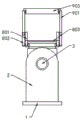
fig. 3 shows a schematic structural diagram of a platen according to an embodiment of the present invention.
Illustration of the drawings:
1. a platen; 2. a side plate; 3. a first motor; 4. a movable block; 5. a groove; 6. a second motor; 7. a movable platform; 8. a clamping portion; 801. a first movable bar; 802. a first electric push rod; 803. pressing a plate; 9. a support portion; 901. a second movable bar; 902. a second electric push rod; 903. and a support plate.
Detailed Description
The technical solutions in the embodiments of the present invention will be described clearly and completely with reference to the accompanying drawings in the embodiments of the present invention, and it is obvious that the described embodiments are only some embodiments of the present invention, not all embodiments. Based on the embodiments of the present invention, all other embodiments obtained by a person of ordinary skill in the art without creative efforts belong to the protection scope of the present invention.
Referring to fig. 1-3, the present invention provides a technical solution: the utility model provides an automatic welding set of small-size engineering machine tool control cabinet, include platen 1 and weld in two curb plates 2 of platen 1's top both sides, the upper end bolted connection of one has first motor 3 in two curb plates 2, and it is connected with movable block 4 to rotate between two curb plates 2, the output shaft and the 4 transmission of movable block of first motor 3 are connected, recess 5 is seted up at movable block 4's top, and the inside bolted connection of recess 5 has second motor 6, the output shaft transmission of second motor 6 is connected with movable platform 7, and movable platform 7 and recess 5's top sliding connection, be equipped with clamping part 8 and supporting part 9 on the movable platform 7, drive through first motor 3 and second motor 6, it is rotatable to make movable block 4 and movable platform 7, and then improved movable platform 7 adjustable angle, make things convenient for equipment to weld.
Specifically, as shown in fig. 2, clamping portions 8 are respectively disposed on two sides of a side end surface of the movable platform 7, a supporting portion 9 is disposed between the two clamping portions 8, and the clamping portions 8 on the two sides work simultaneously, which is helpful for improving stability of workpiece fixing.
Specifically, as shown in fig. 2, the clamping portion 8 includes a first movable rod 801 rotatably connected to the movable platform 7, a first electric push rod 802 is rotatably connected to a side end surface of the first movable rod 801, the first electric push rod 802 is rotatably connected to the movable platform 7, a pressing plate 803 is welded to one end of the first movable rod 801, which is away from the movable platform 7, and the first electric push rod 802 can drive the first movable rod 801 to rotate to fix the workpiece through the pressing plate 803.
Specifically, as shown in fig. 2, the supporting portion 9 includes a second movable rod 901 rotatably connected to the movable platform 7, a side surface wall of the second movable rod 901 is rotatably connected to a second electric push rod 902, and the second electric push rod 902 is rotatably connected to the movable platform 7, one end of the second movable rod 901, which is far away from the movable platform 7, is rotatably connected to a supporting plate 903, and the second electric push rod 902 can drive the second movable rod 901 to rotate, thereby supporting the workpiece through the supporting plate 903.
Specifically, as shown in fig. 1 and 2, the rotatable angle of the movable block 4 is 0 to 180 degrees, the rotatable angle of the first movable rod 801 is 0 to 90 degrees, the rotatable angle of the second movable rod 901 is 0 to 80 degrees, the rotation angle is increased, and the workpiece can be conveniently placed.
The working principle is as follows: when the electric tool is used, commercial power is supplied to the first motor 3, the second motor 6, the first electric push rod 802 and the second electric push rod 902, firstly, a workpiece is placed on the top of the movable platform 7, the first electric push rod 802 is driven to contract, the telescopic end of the first electric push rod 802 drives the first movable rod 801 to rotate, and the first electric push rod 802 rotates while contracting until the pressing plate 803 is attached to the surface of the workpiece; secondly, driving a second electric push rod 902, wherein the telescopic end of the second electric push rod 902 drives a second movable rod 901 to rotate, and the second electric push rod 902 rotates in the contraction process until the supporting plate 903 is attached to the surface of the workpiece; finally, it can drive the movable block 4 rotatory to open first motor 3, it can drive the movable platform 7 rotatory to open second motor 6, fix the work piece on movable platform 7 through clamp plate 803 through foretell step clamping part 8, supporting part 9 has improved the stability of work piece in the rotation through backup pad 903, the fixed bolt that does not use of work piece, and through the drive of first motor 3 and second motor 6, the rotatable scope of work piece has been improved, the welding of work piece has been made things convenient for, and then the fixed inconvenient welding of current automatic welding set mounting fixture and the fragile problem of anchor clamps long-time use have been solved.
The above, only be the concrete implementation of the preferred embodiment of the present invention, but the protection scope of the present invention is not limited thereto, and any person skilled in the art is in the technical scope of the present invention, according to the technical solution of the present invention and the utility model, the concept of which is equivalent to replace or change, should be covered within the protection scope of the present invention.
Claims (7)
1. The utility model provides an automatic welding set of small-size engineering machine tool control cabinet, includes platen (1) and welds two curb plates (2) in the top both sides of platen (1), its characterized in that, the upper end bolted connection of one in two curb plates (2) has first motor (3) to rotate between two curb plates (2) and be connected with movable block (4), the output shaft and the transmission of movable block (4) of first motor (3) are connected, the top of movable block (4) is seted up flutedly (5), and the inside bolted connection of recess (5) has second motor (6), the output shaft transmission of second motor (6) is connected with movable platform (7), and movable platform (7) and the top sliding connection of recess (5), be equipped with clamping part (8) and supporting part (9) on movable platform (7).
2. The automated welding device for the small-sized engineering machinery operating console according to claim 1, characterized in that clamping parts (8) are arranged on both sides of the side end surface of the movable platform (7), and a supporting part (9) is arranged between the two clamping parts (8).
3. The automatic welding device for the small-sized engineering machinery operating console is characterized in that the clamping part (8) comprises a first movable rod (801) rotatably connected with the movable platform (7), a first electric push rod (802) is rotatably connected to the side end face of the first movable rod (801), the first electric push rod (802) is rotatably connected with the movable platform (7), and a pressing plate (803) is welded at one end, away from the movable platform (7), of the first movable rod (801).
4. The automatic welding device for the small-sized engineering machinery operating platform is characterized in that the supporting part (9) comprises a second movable rod (901) which is rotatably connected with the movable platform (7), a side surface wall of the second movable rod (901) is rotatably connected with a second electric push rod (902), the second electric push rod (902) is rotatably connected with the movable platform (7), and one end, far away from the movable platform (7), of the second movable rod (901) is rotatably connected with a supporting plate (903).
5. The automated welding device of a small-sized construction machine console according to claim 1, wherein the angle by which the movable block (4) can rotate is 0 ° to 180 °.
6. The automated welding apparatus of a small-sized construction machine console according to claim 3, wherein the first movable lever (801) is rotatable by an angle of 0 ° to 90 °.
7. The automated welding device of a small-sized construction machine console according to claim 4, wherein the second movable bar (901) is rotatable by an angle of 0 ° to 80 °.
Priority Applications (1)
| Application Number | Priority Date | Filing Date | Title |
|---|---|---|---|
| CN201921348881.0U CN210587905U (en) | 2019-08-20 | 2019-08-20 | Automatic welding device of small-sized engineering machinery control console |
Applications Claiming Priority (1)
| Application Number | Priority Date | Filing Date | Title |
|---|---|---|---|
| CN201921348881.0U CN210587905U (en) | 2019-08-20 | 2019-08-20 | Automatic welding device of small-sized engineering machinery control console |
Publications (1)
| Publication Number | Publication Date |
|---|---|
| CN210587905U true CN210587905U (en) | 2020-05-22 |
Family
ID=70701829
Family Applications (1)
| Application Number | Title | Priority Date | Filing Date |
|---|---|---|---|
| CN201921348881.0U Active CN210587905U (en) | 2019-08-20 | 2019-08-20 | Automatic welding device of small-sized engineering machinery control console |
Country Status (1)
| Country | Link |
|---|---|
| CN (1) | CN210587905U (en) |
Cited By (1)
| Publication number | Priority date | Publication date | Assignee | Title |
|---|---|---|---|---|
| CN111941315A (en) * | 2020-08-12 | 2020-11-17 | 嘉兴学院 | Clamping device for sensor production and processing |
-
2019
- 2019-08-20 CN CN201921348881.0U patent/CN210587905U/en active Active
Cited By (1)
| Publication number | Priority date | Publication date | Assignee | Title |
|---|---|---|---|---|
| CN111941315A (en) * | 2020-08-12 | 2020-11-17 | 嘉兴学院 | Clamping device for sensor production and processing |
Similar Documents
| Publication | Publication Date | Title |
|---|---|---|
| CN210731525U (en) | Automatic welding robot capable of positioning, fixing, clamping and welding | |
| CN213969746U (en) | End beam welding positioner | |
| CN210587905U (en) | Automatic welding device of small-sized engineering machinery control console | |
| CN217776079U (en) | Auxiliary clamping device with variable welding angle | |
| CN210997176U (en) | Vertical long-axis pump production is with takeover welding set | |
| CN218946990U (en) | Stop valve processing positioning fixture | |
| CN219324931U (en) | Welding fixture for dryer support assembly | |
| CN216066228U (en) | Fixed frock of locate mode flange joint pipe | |
| CN215356420U (en) | High-precision steel structure section bar cutting device | |
| CN213289509U (en) | Clamping device is used in machine part processing | |
| CN220128577U (en) | Fixing tool for machining engine water pump belt pulley | |
| CN219837298U (en) | Arc welding clamp capable of improving part pressing force | |
| CN213135701U (en) | Improved steel pipe furniture high-numerical control welding platform | |
| CN213321778U (en) | Sealing strip welding equipment | |
| CN211508856U (en) | Brushless motor rotor inserts axle positioner | |
| CN217513230U (en) | Fixture for welding electromechanical equipment parts | |
| CN215509716U (en) | Workpiece fixing device of automatic welding machine | |
| CN220146151U (en) | Automatic hole melting device for MPP power tube | |
| CN219684598U (en) | Machining positioning device | |
| CN212599443U (en) | Cutting device is used in processing of industrial motor part | |
| CN218194844U (en) | Excavator bucket rod assembling and positioning device | |
| CN212435256U (en) | Cable clamping device | |
| CN218855998U (en) | Wind-powered electricity generation sliding ring welding set with mechanism of rectifying | |
| CN218426354U (en) | Laser welding machine anchor clamps | |
| CN214291701U (en) | Multifunctional shifting clamp holder |
Legal Events
| Date | Code | Title | Description |
|---|---|---|---|
| GR01 | Patent grant | ||
| GR01 | Patent grant |