CN210585827U - Multifunctional efficient vibrating screen - Google Patents
Multifunctional efficient vibrating screen Download PDFInfo
- Publication number
- CN210585827U CN210585827U CN201921547294.4U CN201921547294U CN210585827U CN 210585827 U CN210585827 U CN 210585827U CN 201921547294 U CN201921547294 U CN 201921547294U CN 210585827 U CN210585827 U CN 210585827U
- Authority
- CN
- China
- Prior art keywords
- shell
- vibrating screen
- wall
- multifunctional efficient
- bottom end
- Prior art date
- Legal status (The legal status is an assumption and is not a legal conclusion. Google has not performed a legal analysis and makes no representation as to the accuracy of the status listed.)
- Expired - Fee Related
Links
- 239000000463 material Substances 0.000 claims abstract description 36
- 238000013016 damping Methods 0.000 claims abstract description 17
- 230000007246 mechanism Effects 0.000 claims abstract description 11
- 238000007789 sealing Methods 0.000 claims description 9
- 230000000694 effects Effects 0.000 abstract description 10
- 238000012216 screening Methods 0.000 abstract description 9
- 230000003139 buffering effect Effects 0.000 abstract description 3
- 238000007873 sieving Methods 0.000 abstract description 3
- 230000035939 shock Effects 0.000 description 6
- 238000000034 method Methods 0.000 description 5
- 239000004576 sand Substances 0.000 description 4
- 238000010586 diagram Methods 0.000 description 3
- 238000007599 discharging Methods 0.000 description 3
- 238000003466 welding Methods 0.000 description 3
- 238000007664 blowing Methods 0.000 description 2
- 230000009286 beneficial effect Effects 0.000 description 1
- 238000012824 chemical production Methods 0.000 description 1
- 238000004140 cleaning Methods 0.000 description 1
- 230000002301 combined effect Effects 0.000 description 1
- 238000001816 cooling Methods 0.000 description 1
- 230000007547 defect Effects 0.000 description 1
- 238000001035 drying Methods 0.000 description 1
- 230000005284 excitation Effects 0.000 description 1
- 239000011343 solid material Substances 0.000 description 1
- 239000002699 waste material Substances 0.000 description 1
Images


Landscapes
- Combined Means For Separation Of Solids (AREA)
Abstract
The utility model discloses a multifunctional high-efficiency vibrating screen, which comprises a shell, wherein a feed inlet is arranged on one side of the top end of the shell, the inner wall of the feed inlet is provided with a feed hopper, a discharge outlet is arranged on the bottom end of the shell, the inner wall of the discharge outlet is provided with a discharge hopper, and the top parts of the inner walls on the two sides of the shell are provided with buffer plates; the both sides inner wall of casing all is provided with auxiliary housing, and is provided with actuating mechanism in the auxiliary housing, is provided with the bank of screens more than two between two auxiliary housings, and open on the top of bank of screens has the opening, and the inner wall of opening is provided with the sieve, the sieve is network structure, two the buffer board is crisscross to be distributed. The utility model discloses a set up the buffer board, and the buffer board is crisscross to be distributed, and the length of the buffer board of below is less than the length of buffer board of above, can play the effect of guide, has reduced the speed that the material falls simultaneously, has reduced screening pressure; thereby reducing the working pressure of the sieve plate, improving the sieving uniformity and efficiency and playing a role in damping and buffering.
Description
Technical Field
The utility model particularly relates to a shale shaker specifically is a multi-functional high-efficient shale shaker.
Background
In chemical production, fluidized beds are often used for drying and cooling processes of granular solid materials. However, the fluidized bed occupies a large area, the equipment cost is high, and the cleaning is difficult. Therefore, in the existing process, a vibrating screen is often used to replace the fluidized bed.
The vibrating screen operates by utilizing reciprocating rotary type vibration generated by vibrator excitation. The upper rotary heavy hammer of the vibrator makes the screen surface generate plane rotary vibration, the lower rotary heavy hammer makes the screen surface generate conical surface rotary vibration, and the combined effect makes the screen surface generate re-rotary vibration.
Through retrieval, the Chinese patent with the application number of CN201720052434.5 discloses a multifunctional vibrating screen, which comprises a vibrating screen main body and a blowing system, wherein the vibrating screen main body is connected to a base through an elastic mechanism arranged at the bottom; the vibrating screen comprises a vibrating screen body and a vibrating screen body, wherein the vibrating screen body comprises a screen plate arranged in the vibrating screen body, a plurality of air inlets arranged on the side wall, a feed inlet and a tail gas outlet which are arranged at the upper part, a discharge outlet which is arranged at the lower part and a vibrating motor which can drive the vibrating screen body to vibrate; the air blowing system is communicated with the interior of the vibrating screen main body through an air inlet; the vibrating screen is characterized in that the screen plates are provided with at least two layers, a guide plate is arranged below each layer of screen plate, the guide plate is concave downwards along the edge inside the vibrating screen towards the center, and the center part of the guide plate is separately provided with a guide opening. The multifunctional vibrating screen in the patent has the following defects: when the device is used, the descending speed of materials is too high, and the screening pressure on the vibrating screen plate is large; the screening efficiency is low and the phenomenon of non-uniform screening is easy to occur.
SUMMERY OF THE UTILITY MODEL
An object of the utility model is to provide a multi-functional high-efficient shale shaker to solve the problem that proposes among the above-mentioned background art.
In order to achieve the above object, the utility model provides a following technical scheme:
a multifunctional efficient vibrating screen comprises a shell, wherein a feed inlet is formed in one side of the top end of the shell, a feed hopper is arranged on the inner wall of the feed inlet, a discharge outlet is formed in the bottom end of the shell, a discharge hopper is arranged on the inner wall of the discharge outlet, and buffer plates are arranged on the tops of the inner walls of the two sides of the shell; the both sides inner wall of casing all is provided with auxiliary housing, and is provided with actuating mechanism in the auxiliary housing, is provided with the bank of screens more than two between two auxiliary housings, and open on the top of bank of screens has the opening, and the inner wall of opening is provided with the sieve, the sieve is network structure.
As a further aspect of the present invention: the two buffer plates are distributed in a staggered mode, and the length of the buffer plate located below is smaller than that of the buffer plate located above.
As a further aspect of the present invention: the inner wall of the bottom end of the shell is provided with a material guide hopper which is of a hollow step-shaped structure, and the small end of the material guide hopper faces downwards.
As a further aspect of the present invention: the driving mechanism comprises a vibration motor, a supporting plate is arranged on the inner wall of the auxiliary shell, the vibration motor is arranged at the top end of the supporting plate, a connecting frame is arranged at the top end of the vibration motor, a sliding rail is arranged at one end of the connecting frame, and the screen frame is connected in the sliding rail in a sliding manner; the lateral wall of casing is opened there is the side mouth, and it has the side cover to articulate in the side mouth.
As a further aspect of the present invention: the four corners of casing bottom all is provided with damper, damper includes base and supporting shoe, and the supporting shoe sets up in the bottom of casing, and open on the top of base has the opening, and supporting shoe sliding connection is in the opening, and the bottom of supporting shoe is provided with the dog, and the specification of dog is greater than the open-ended bore, and the bottom inner wall of base is provided with damping spring, and damping spring sets up in the bottom of dog.
As a further aspect of the present invention: the top of feeder hopper both sides outer wall all is provided with the sand grip, and it has the spout to open in the sand grip, and sliding connection has same top cap in two spouts.
As a further aspect of the present invention: one side of the auxiliary shell is provided with a rectangular through hole, the connecting frame is inserted into the rectangular through hole, and the inner wall of the rectangular through hole is bonded with a sealing sleeve.
As a further aspect of the present invention: the sealing sleeve is of a spring type rubber pad structure; the top end of the auxiliary shell is of an inclined structure.
Compared with the prior art, the beneficial effects of the utility model are that:
1. by arranging the buffer plates which are distributed in a staggered manner, the length of the buffer plate below is smaller than that of the buffer plate above, so that the material guiding effect can be achieved, the falling speed of the material is reduced, and the screening pressure is reduced; thereby reducing the working pressure of the sieve plate and improving the sieving uniformity and efficiency.
2. By arranging the material guide hopper, the small end of the material guide hopper faces downwards, so that the four walls are ensured to incline downwards, the materials are effectively guided out, and the residues of the materials in the shell are reduced; set up the seal cover simultaneously, the seal cover is spring rubber pad structure, has ensured the leakproofness under the condition that does not influence the link vibration, and the top of auxiliary housing sets up to slope column structure, can incline the guide, reduces the material and remains in equipment, has reduced the wasting of resources.
3. The base, the supporting block and the damping spring are arranged, so that the damping and buffering effects are achieved, the noise generated by the operation of the equipment is reduced, and the stability of the equipment is guaranteed under the condition that the damping effect is not influenced by the supporting block and the base; and meanwhile, a stop block is arranged, and the specification of the stop block is greater than the caliber of the opening, so that the supporting block is prevented from being separated from the base.
4. The side wall of the connecting frame is provided with the slide rail, so that the sieve frame can be taken down in a sliding mode, and materials at the upper end of the sieve plate are collected and cleaned; and meanwhile, the top cover is connected onto the feed hopper through the sliding groove, so that the feed hopper is convenient to open and close.
Drawings
Fig. 1 is a schematic structural diagram of a multifunctional efficient vibrating screen.
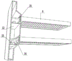
Fig. 2 is a schematic structural diagram of an auxiliary shell in a multifunctional high-efficiency vibrating screen.
Fig. 3 is a schematic structural diagram of a base in a multifunctional high-efficiency vibrating screen.
In the figure: the device comprises a shell 1, a feed hopper 2, a top cover 3, a buffer plate 4, an auxiliary shell 5, a screen frame 6, a material guide hopper 7, a material discharge hopper 8, a base 9, a support block 10, a screen plate 11, a support plate 12, a vibration motor 13, a connecting frame 14, a sealing sleeve 15 and a damping spring 16.
Detailed Description
The technical solutions in the embodiments of the present invention will be described clearly and completely with reference to the accompanying drawings in the embodiments of the present invention, and it is obvious that the described embodiments are only some embodiments of the present invention, not all embodiments. Based on the embodiments in the present invention, all other embodiments obtained by a person skilled in the art without creative work belong to the protection scope of the present invention.
Example 1
Referring to fig. 1-3, in an embodiment of the present invention, a multifunctional high-efficiency vibrating screen includes a casing 1, a feeding port is formed at one side of a top end of the casing 1, a feeding hopper 2 is welded to an inner wall of the feeding port, a discharging port is formed at a bottom end of the casing 1, and a discharging hopper 8 is welded to an inner wall of the discharging port; the buffer plates 4 are welded at the tops of the inner walls of the two sides of the shell 1, the buffer plates 4 are distributed in a staggered mode, the length of the buffer plate 4 positioned below is smaller than that of the buffer plate 4 positioned above, a material guide effect can be achieved, the falling speed of materials is reduced, and the screening pressure is reduced; the both sides inner wall of casing 1 all welds and has auxiliary housing 5, and is provided with actuating mechanism in the auxiliary housing 5, and actuating mechanism is used for the drive to screening work, is provided with more than two bank 6 between two auxiliary housing 5, and open on the top of bank 6 has the opening, and the inner wall of opening has sieve 11 through the fix with screw, does not add the injecing to the specification of sieve 11, in this embodiment, and is preferred, sieve 11 is network structure.
The utility model discloses in, the bottom inner wall welding of casing 1 has guide fill 7, and the use of guide fill 7 can play the effect of deriving the screening material, does not add the injecing to the specification of guide fill 7, in this embodiment, and is preferred, guide fill 7 is hollow halfpace column structure, and the osculum end of guide fill 7 is down to guarantee that four wall slopes downwards, effectively derive the material, reduce remaining of material in casing 1.
In the utility model, the driving mechanism comprises a vibrating motor 13, a supporting plate 12 is welded on the inner wall of the auxiliary shell 5, the vibrating motor 13 is fixed at the top end of the supporting plate 12 through screws, a connecting frame 14 is arranged at the top end of the vibrating motor 13, a sliding rail is fixed at one end of the connecting frame 14 through screws, the sieve frame 6 is connected in the sliding rail in a sliding way, the sieve frame 6 can be taken down in a sliding way, and therefore materials at the upper end of the sieve plate 11 are collected and cleaned; the lateral wall of the shell 1 is provided with a side opening, and a side cover is hinged in the side opening, so that the sieve frame 6 can be taken out conveniently.
The utility model discloses in, the four corners of 1 bottom of casing all is provided with damper for the shock attenuation to equipment, damper can be spring shock attenuation, hydraulic shock attenuation or atmospheric pressure shock attenuation, in this embodiment, it is preferred, damper includes base 9 and supporting shoe 10, supporting shoe 10 welds in 1 bottom of casing, open on 9's top has the opening, supporting shoe 10 sliding connection has in the opening, the bottom welding of supporting shoe 10 has the dog, the specification of dog is greater than the open-ended bore, thereby avoid supporting shoe 10 to break away from the phenomenon emergence of base 9, the bottom inner wall welding of base 9 has damping spring 16, damping spring 16 welds in the bottom of dog, the effect of shock attenuation buffering has been played, the noise that equipment work produced has been reduced, and supporting shoe 10 and base 9 are under the shock attenuation effect is not influenced, the stability of equipment has been ensured.
The utility model discloses in, the sand grip has all been welded on the top of 2 both sides outer walls of feeder hopper, and it has the spout to open in the sand grip, and sliding connection has same top cap 3 in two spouts to make things convenient for the closure of feeder hopper 2.
The utility model discloses a theory of operation is: fixing the equipment in a proper position and connecting a power supply; the top cover 3 is opened by sliding the top cover 3, materials are added into the shell 1 through the feed hopper 2, the materials fall onto the buffer plate 4 and are buffered through the guide of the buffer plate 4, the falling speed of the materials is reduced, meanwhile, the vibration motor 13 is started, the vibration motor 13 works to drive the connecting frame 14 to vibrate, the vibration sieve plate 11 is further vibrated to sieve the materials, and fine materials are led out through the guide hopper 7; the vibration is generated in the working process of the equipment, and the damping spring 16 has good damping effect.
Example 2
Referring to fig. 2, in an embodiment of the present invention, in order to prevent a material from entering into the auxiliary housing 5 during a screening process, the following improvements are made in this embodiment on the basis of embodiment 1: in the embodiment, preferably, the sealing sleeve 15 is of a spring type rubber pad structure, and the sealing performance is guaranteed under the condition that the vibration of the connecting frame 14 is not influenced; the top end of the auxiliary shell 5 is of an inclined structure, so that the materials can be guided in an inclined mode, the residue of the materials in the equipment is reduced, and the resource waste is reduced.
The utility model discloses a theory of operation is: fixing the equipment in a proper position and connecting a power supply; the top cover 3 is opened by sliding the top cover 3, materials are added into the shell 1 through the feed hopper 2, the materials fall onto the buffer plate 4 and are buffered through the guide of the buffer plate 4, the falling speed of the materials is reduced, meanwhile, the vibration motor 13 is started, the vibration motor 13 works to drive the connecting frame 14 to vibrate, the sealing sleeve 15 ensures the sealing effect between the connecting frame 14 and the auxiliary shell 5, the vibration sieve plate 11 is used for sieving the materials, and fine materials are led out through the guide hopper 7; the vibration is generated in the working process of the equipment, and the damping spring 16 has good damping effect.
It is obvious to a person skilled in the art that the invention is not restricted to details of the above-described exemplary embodiments, but that it can be implemented in other specific forms without departing from the spirit or essential characteristics of the invention. The present embodiments are therefore to be considered in all respects as illustrative and not restrictive, the scope of the invention being indicated by the appended claims rather than by the foregoing description, and all changes which come within the meaning and range of equivalency of the claims are therefore intended to be embraced therein. Any reference sign in a claim should not be construed as limiting the claim concerned.
Furthermore, it should be understood that although the present description refers to embodiments, not every embodiment may contain only a single embodiment, and such description is for clarity only, and those skilled in the art should integrate the description, and the embodiments may be combined as appropriate to form other embodiments understood by those skilled in the art.
Claims (8)
1. A multifunctional efficient vibrating screen comprises a shell (1), wherein a feed inlet is formed in one side of the top end of the shell (1), a feed hopper (2) is arranged on the inner wall of the feed inlet, a discharge outlet is formed in the bottom end of the shell (1), and a discharge hopper (8) is arranged on the inner wall of the discharge outlet, and the multifunctional efficient vibrating screen is characterized in that a buffer plate (4) is arranged on the top of each of the inner walls of the two sides of the shell (1); the inner walls of two sides of the shell (1) are provided with auxiliary shells (5), a driving mechanism is arranged in each auxiliary shell (5), more than two sieve frames (6) are arranged between the two auxiliary shells (5), openings are formed in the top ends of the sieve frames (6), sieve plates (11) are arranged on the inner walls of the openings, and the sieve plates (11) are of net-shaped structures.
2. A multifunctional high-efficiency vibrating screen according to claim 1, characterized in that two said buffer plates (4) are staggered, the length of the lower buffer plate (4) being less than the length of the upper buffer plate (4).
3. The multifunctional efficient vibrating screen is characterized in that a material guide hopper (7) is arranged on the inner wall of the bottom end of the shell (1), the material guide hopper (7) is of a hollow step-shaped structure, and the small end of the material guide hopper (7) faces downwards.
4. The multifunctional efficient vibrating screen is characterized in that the driving mechanism comprises a vibrating motor (13), a supporting plate (12) is arranged on the inner wall of the auxiliary shell (5), the vibrating motor (13) is arranged at the top end of the supporting plate (12), a connecting frame (14) is arranged at the top end of the vibrating motor (13), a sliding rail is arranged at one end of the connecting frame (14), and the screen frame (6) is connected in the sliding rail in a sliding manner; the side wall of the shell (1) is provided with a side opening, and a side cover is hinged in the side opening.
5. The multifunctional efficient vibrating screen is characterized in that four corners of the bottom end of the casing (1) are provided with damping mechanisms, each damping mechanism comprises a base (9) and a supporting block (10), each supporting block (10) is arranged at the bottom end of the casing (1), an opening is formed in the top end of the base (9), the supporting blocks (10) are connected in the openings in a sliding mode, a stop block is arranged at the bottom end of each supporting block (10), the size of each stop block is larger than the caliber of each opening, a damping spring (16) is arranged on the inner wall of the bottom end of each base (9), and each damping spring (16) is arranged at the bottom end of each stop block.
6. The multifunctional efficient vibrating screen is characterized in that convex strips are arranged at the top ends of the outer walls of the two sides of the feeding hopper (2), sliding grooves are formed in the convex strips, and the same top cover (3) is connected in the two sliding grooves in a sliding mode.
7. The multifunctional efficient vibrating screen is characterized in that a rectangular through hole is formed in one side of the auxiliary shell (5), the connecting frame (14) is inserted into the rectangular through hole, and a sealing sleeve (15) is bonded to the inner wall of the rectangular through hole.
8. The multifunctional efficient vibrating screen is characterized in that the sealing sleeve (15) is of a spring type rubber pad structure; the top end of the auxiliary shell (5) is of an inclined structure.
Priority Applications (1)
| Application Number | Priority Date | Filing Date | Title |
|---|---|---|---|
| CN201921547294.4U CN210585827U (en) | 2019-09-17 | 2019-09-17 | Multifunctional efficient vibrating screen |
Applications Claiming Priority (1)
| Application Number | Priority Date | Filing Date | Title |
|---|---|---|---|
| CN201921547294.4U CN210585827U (en) | 2019-09-17 | 2019-09-17 | Multifunctional efficient vibrating screen |
Publications (1)
| Publication Number | Publication Date |
|---|---|
| CN210585827U true CN210585827U (en) | 2020-05-22 |
Family
ID=70720775
Family Applications (1)
| Application Number | Title | Priority Date | Filing Date |
|---|---|---|---|
| CN201921547294.4U Expired - Fee Related CN210585827U (en) | 2019-09-17 | 2019-09-17 | Multifunctional efficient vibrating screen |
Country Status (1)
| Country | Link |
|---|---|
| CN (1) | CN210585827U (en) |
Cited By (1)
| Publication number | Priority date | Publication date | Assignee | Title |
|---|---|---|---|---|
| CN113441391A (en) * | 2021-07-16 | 2021-09-28 | 安徽中科春谷激光产业技术研究院有限公司 | Laser cladding powder collection device |
-
2019
- 2019-09-17 CN CN201921547294.4U patent/CN210585827U/en not_active Expired - Fee Related
Cited By (1)
| Publication number | Priority date | Publication date | Assignee | Title |
|---|---|---|---|---|
| CN113441391A (en) * | 2021-07-16 | 2021-09-28 | 安徽中科春谷激光产业技术研究院有限公司 | Laser cladding powder collection device |
Similar Documents
| Publication | Publication Date | Title |
|---|---|---|
| CN210434853U (en) | A linear vibrating screen | |
| CN206435464U (en) | A kind of ternary spin vibration sieve | |
| CN214865083U (en) | Circulating sand screening device for building engineering | |
| CN212418638U (en) | Vibrating screen for secondary screening | |
| CN201055844Y (en) | Multiple response type rotary and vibrating screen | |
| AU746748B2 (en) | A screenless vibrator separator | |
| CN206897814U (en) | A kind of two-stage sorting unit | |
| CN221132353U (en) | Impurity removing device for rice processing | |
| CN213377737U (en) | Section flip-flow screen | |
| CN218370572U (en) | High-frequency screen feeding buffer device | |
| CN215465989U (en) | High-efficient environment-friendly is from cleaning sieve | |
| CN110681572A (en) | Adjustable vibration excitation vibration screen box | |
| CN214132661U (en) | But veneer oriented structure board wood shavings sieving mechanism | |
| CN207914103U (en) | Accurate screening machine | |
| CN210965881U (en) | Efficient vibration screening machine for carburant production | |
| CN207103119U (en) | Flour sieving device is used in a kind of wafer production | |
| CN212596955U (en) | Shale shaker for feed processing with edulcoration function | |
| CN221753608U (en) | A high-efficiency spiral chute for mineral processing | |
| CN209077118U (en) | A kind of aggregate production tilting vibration separation screen | |
| CN213762763U (en) | Disc filter screen convenient to change | |
| CN221620007U (en) | Square swinging screen feed inlet with buffering effect | |
| CN207154124U (en) | Environmentally friendly complex vibration straight line shaker | |
| CN217250501U (en) | Novel high-productivity screening square swing screen | |
| CN219560386U (en) | Brain dry powder screening machine | |
| CN217342270U (en) | Vibrating type efficient discharging hopper for carburant production |
Legal Events
| Date | Code | Title | Description |
|---|---|---|---|
| GR01 | Patent grant | ||
| GR01 | Patent grant | ||
| CF01 | Termination of patent right due to non-payment of annual fee | ||
| CF01 | Termination of patent right due to non-payment of annual fee |
Granted publication date: 20200522 |