CN210550960U - Combined multifunctional wrench - Google Patents
Combined multifunctional wrench Download PDFInfo
- Publication number
- CN210550960U CN210550960U CN201920859201.5U CN201920859201U CN210550960U CN 210550960 U CN210550960 U CN 210550960U CN 201920859201 U CN201920859201 U CN 201920859201U CN 210550960 U CN210550960 U CN 210550960U
- Authority
- CN
- China
- Prior art keywords
- holding rod
- tail
- centimeters
- end tail
- rivet
- Prior art date
- Legal status (The legal status is an assumption and is not a legal conclusion. Google has not performed a legal analysis and makes no representation as to the accuracy of the status listed.)
- Active
Links
Images


Landscapes
- Details Of Spanners, Wrenches, And Screw Drivers And Accessories (AREA)
Abstract
The utility model discloses a combined multifunctional wrench, which comprises a holding rod and an end tail, wherein the holding rod is arranged on the upper side of the right end of the end tail, the holding rod is connected with the right side of the upper end of the end tail through welding, the holding rod is connected with the end tail through welding, the end tail comprises a screwdriver, a main body, a shaft hole and a connecting part, the end tail can play the role of a crowbar by arranging the end tail into a cone-shaped structure in the utility model, when a certain article needs to be pried open, the multifunctional wrench can be opened under the action of the end tail, so that the application range of the multifunctional wrench is wider, in the utility model, the screwdriver is arranged at one end of the end tail, which is far away from the holding rod, and the screwdriver is connected with the end tail through welding, so that the multifunctional wrench can better detach the screw through the screwdriver.
Description
Technical Field
The utility model belongs to the technical field of the production tool is relevant, concretely relates to modular multi-functional spanner.
Background
A wrench is a common installation and removal tool. Hand tools for turning bolts, screws, nuts and other threaded fasteners for tightening openings or trepanning of bolts or nuts using the principle of leverage. The wrench is usually provided with an opening or a trepan for clamping the handle part and applying external force to the handle part so as to screw the bolt or the nut to hold the bolt or the nut, at one end or two ends of the handle part. When the screw is used, external force is applied to the handle part along the rotation direction of the screw thread, and the bolt or the nut can be screwed.
The prior multifunctional wrench technology has the following problems: the existing multifunctional wrench has a plurality of shapes when being used, so that the multifunctional wrench can be used for screwing bolts of different sizes and other objects, but when the screws are required to be disassembled, a professional tool is required to be used, and meanwhile, when certain objects are required to be pried, the multifunctional wrench cannot be pried well, and does not have the function.
SUMMERY OF THE UTILITY MODEL
An object of the utility model is to provide a modular multi-functional spanner to solve the current multi-functional spanner that proposes in the above-mentioned background art and only possess the function of unscrewing the bolt and prying open other article and do not possess the problem of the phenomenon of the function of dismantling the screw.
In order to achieve the above object, the utility model provides a following technical scheme: a combined multifunctional wrench comprises a holding rod and an end tail, wherein the holding rod is arranged on the upper side of the right end of the end tail and is connected to the right side of the upper end of the end tail in a welding manner, the holding rod is connected with the end tail in a welding manner, the end tail comprises a screwdriver, a main body, a shaft hole and a connecting part, the main body is arranged at the upper end of the screwdriver, the connecting part is arranged at the upper end of the main body, the shaft hole is formed in the inner side of the intersection of the connecting part and the main body, a protective sleeve is arranged at the surface end outside the intersection of the holding rod and the end tail, the protective sleeve is connected with the holding rod in a sleeving manner, a rotating part is arranged at the upper end of the holding rod and is connected with the surface end outside the upper end of the holding rod in a sleeving manner, first clamping teeth are arranged at the upper end of the rotating part and are connected with the holding rod in a welding manner, the upper end of the first clamping tooth is provided with a second clamping tooth, and the second clamping tooth is connected with the rotating part in a welding mode.
Preferably, the protecting sleeve comprises a first sleeve opening, an anti-slip part and a second sleeve opening, the anti-slip part is arranged at the upper end of the first sleeve opening, the second sleeve opening is arranged at the upper end of the anti-slip part, and the protecting sleeve is connected with the holding rod through the anti-slip part in a sleeved mode.
Preferably, the constitution of rotation portion is including first rivet, curb plate, second rivet, limiting plate and spring, the inside of the left end of limiting plate is run through and is provided with the second rivet, the lower extreme of second rivet is provided with the spring, the upper end of second rivet runs through and is provided with the curb plate, the left end of curb plate runs through and is provided with first rivet, rotation portion is connected through cup jointing through first rivet and holding pole.
Preferably, the first clamping teeth and the second clamping teeth are arranged oppositely, and racks are arranged on the inner sides of the first clamping teeth and the inner sides of the second clamping teeth which are opposite.
Preferably, the end tail is of an awl-shaped structure, the length of the end tail is three centimeters, the width of the longest edge of the end tail is three points and five centimeters, and the width of the tip of the end tail is zero point and eight centimeters.
Preferably, the holding rod is of a flat rectangular structure, the length of the holding rod is eighteen centimeters, the thickness of the holding rod is a zero point eight centimeters, and the width of the holding rod is three centimeters.
Preferably, the maximum size of the openings of the first clamping tooth and the second clamping tooth is three to six centimeters, and the outer surface ends of the first clamping tooth and the second clamping tooth are processed through electrophoresis.
Preferably, the length of the antiskid part is six centimeters, and the surface end of the outer side of the antiskid part is provided with an antiskid stripe on one side.
Compared with the prior art, the utility model provides a modular multi-functional spanner possesses following beneficial effect:
(1) the end tail is arranged into a cone-shaped structure in the utility model, so that the end tail can play the role of a crowbar, and can be opened under the action of the end tail when a certain article needs to be pried open, so that the multifunctional wrench has a wider application range, and the problem that the existing multifunctional wrench only has the functions of unscrewing bolts and priing other articles and does not have the function of detaching the bolts is solved;
(2) the utility model discloses in be provided with the screwdriver through the one end of holding the pole of keeping away from at the end tail to this screwdriver passes through welded connection with the end tail, can be so that can be better through the effect of dismantling the screw at this multi-functional spanner, thereby solved current multi-functional spanner and only possessed the problem that the function of unscrewing the bolt and prying open other article does not possess the phenomenon of the function of dismantling the screw.
Drawings
FIG. 1 is a schematic view of the multi-functional wrench assembly of the present invention;
FIG. 2 is a schematic end-to-end structure of the present invention;
FIG. 3 is a schematic view of the structure of the protective cover of the present invention;
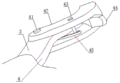
fig. 4 is a schematic view of the structure of the rotating part of the present invention;
in the figure: 1. end-to-end; 11. a screwdriver; 12. a main body; 13. a shaft hole; 14. a connecting portion; 2. a protective sleeve; 21. a first cuff; 22. an anti-slip portion; 23. a second cuff; 3. holding the rod; 4. a rotating part; 41. a first rivet; 42. a side plate; 43. a second rivet; 44. a limiting plate; 45. a spring; 5. a first clamping tooth; 6. a second clamping tooth.
Detailed Description
The technical solutions in the embodiments of the present invention will be described clearly and completely with reference to the accompanying drawings in the embodiments of the present invention, and it is obvious that the described embodiments are only some embodiments of the present invention, not all embodiments. Based on the embodiments in the present invention, all other embodiments obtained by a person skilled in the art without creative work belong to the protection scope of the present invention.
Referring to fig. 1-4, the present invention provides a technical solution: a combined multifunctional wrench comprises a holding rod 3 and an end tail 1, wherein the end tail 1 is of a cone-shaped structure, the length of the end tail 1 is three centimeters, the end tail 1 can have the function of a crowbar by arranging the end tail 1, so that a packing box of some objects can be pried open, the width of the longest edge of the end tail 1 is three points and five centimeters, the width of the tip end of the end tail 1 is eight centimeters at zero, the holding rod 3 is arranged on the upper side of the right end of the end tail 1, the holding rod 3 is connected to the right side of the upper end of the end tail 1 by welding, the holding rod 3 is connected with the end tail 1 by welding, the end tail 1 comprises a screwdriver 11, a main body 12, a shaft hole 13 and a connecting part 14, the upper end of the screwdriver 11 is provided with the main body 12, the connecting part 14 is arranged on the upper end of the main body 12, the shaft hole 13 is arranged on the inner side of the intersection of the connecting part 14 and the main body 12, a protective sleeve 2 is arranged on the, the holding rod 3 is a flat rectangular structure, the setting of the ampere rule rod 3 can enable a user to exert strength to the maximum extent under the action of the holding rod 3, so that better fixation can be realized, the length of the holding rod 3 is eighteen centimeters, the thickness of the holding rod 3 is zero point eight centimeters, the width of the holding rod 3 is three centimeters, the protecting sleeve 2 comprises a first sleeve opening 21, an anti-skidding part 22 and a second sleeve opening 23, the upper end of the first sleeve opening 21 is provided with the anti-skidding part 22, the length of the anti-skidding part 22 is six centimeters, the surface end of the outer side of the anti-skidding part 22 is provided with one-side anti-skidding stripes, the outer side of the anti-skidding part 22 is provided with the anti-skidding stripes, so that the anti-skidding part 22 can enable the user not to fall off when holding under the action of the anti-skidding stripes, the upper end of the anti-skidding part 22 is provided with the second sleeve opening 23, through the arrangement of the first sleeve opening 21 and the second sleeve opening 23, the protective sleeve 2 can be better sleeved at the surface end of the holding rod 3 through the first sleeve opening 21 and the second sleeve opening 23, the protective sleeve 2 is connected with the holding rod 3 through the anti-skid part 22,
a combined multifunctional wrench comprises a protective sleeve 2 and a holding rod 3 which are connected through a sleeve, a rotating part 4 is arranged at the upper end of the holding rod 3, the rotating part 4 comprises a first rivet 41, a side plate 42, a second rivet 43, a limiting plate 44 and a spring 45, the inside of the left end of the limiting plate 44 is provided with the second rivet 43 in a penetrating way, the lower end of the second rivet 43 is provided with the spring 45, the upper end of the second rivet 43 is provided with the side plate 42 in a penetrating way, the side plate 42 is arranged through the side plate 42, so that the side plate 42 can better fix the wrench under the action, the left end of the side plate 42 is provided with the first rivet 41 in a penetrating way, the rotating part 4 is connected with the holding rod 3 through the first rivet 41 in a sleeve way, the rotating part 4 is connected with the meter end at the outer side of the upper end of the holding rod 3 through a sleeve way, the upper end of the rotating part 4 is provided with a first clamping tooth 5, and the first clamping, the opposite inner sides of the first clamping teeth 5 and the second clamping teeth 6 are provided with racks, the surface ends of the first clamping teeth 5 and the second clamping teeth 6 are provided with the racks, so that the first clamping teeth 5 and the second clamping teeth 6 can better rotate an object to be screwed under the action of the racks, the maximum size of openings of the first clamping teeth 5 and the second clamping teeth 6 is three to six centimeters, the surface ends of the outer sides of the first clamping teeth 5 and the second clamping teeth 6 are subjected to electrophoresis treatment, the surface ends of the first clamping teeth 5 and the second clamping teeth 6 are subjected to electrophoresis treatment, the first clamping teeth 5 and the second clamping teeth 6 can better work, the first clamping teeth 5 and the holding rod 3 are connected in a welding mode, the upper ends of the first clamping teeth 5 are provided with the second clamping teeth 6, and the second clamping teeth 6 are connected with the rotating portion 4 in a welding mode.
The utility model discloses a theory of operation and use flow: after the utility model is installed, when the spanner is needed to be used, the spanner is firstly taken out, then the protective sleeve 2 is sleeved at the surface end of the holding rod 3, so that the spanner can be better held when the spanner is needed to be held through the effect of the protective sleeve 2, then when the bolt is needed to be screwed and unscrewed, at this time, the first clamping tooth 5 and the second clamping tooth 6 are sleeved at the surface end of the bolt to be operated through a user, the opening angle between the first clamping tooth 5 and the second clamping tooth 6 is adjusted, the bolt to be unscrewed or screwed can be better fixed under the effect of the internal spring 45, so that the bolt to be unscrewed or screwed can be operated under the effect of the first clamping tooth 5 and the second clamping tooth 6, meanwhile, the maximum opening distance between the first clamping tooth 5 and the second clamping tooth 6 is six centimeters, so that the spanner can be better operated, simultaneously the end tail 1 of this spanner can act as the use of crowbar, can be so that pry open the packing box, is provided with screwdriver 11 through the one end of taking holding pole 3 of keeping away from at end tail 1 moreover to this screwdriver 11 passes through welded connection with end tail 1, can so that can be better through this screwdriver 11 at this multi-functional spanner dismantle the effect of screw, just so accomplished the use of this spanner.
Although embodiments of the present invention have been shown and described, it will be appreciated by those skilled in the art that changes, modifications, substitutions and alterations can be made in these embodiments without departing from the principles and spirit of the invention, the scope of which is defined in the appended claims and their equivalents.
Claims (8)
1. The utility model provides a modular multi-functional spanner, is including holding pole (3) and end tail (1), its characterized in that: the upper side of the right end of the end tail (1) is provided with a holding rod (3), the holding rod (3) is connected to the right side of the upper end of the end tail (1) through welding, the holding rod (3) is connected with the end tail (1) through welding, the end tail (1) comprises a screwdriver (11), a main body (12), a shaft hole (13) and a connecting part (14), the upper end of the screwdriver (11) is provided with the main body (12), the upper end of the main body (12) is provided with the connecting part (14), the inner side of the intersection of the connecting part (14) and the main body (12) is provided with the shaft hole (13), the surface end of the outer side of the intersection of the holding rod (3) and the end tail (1) is provided with a protective sleeve holding part (2), the protective sleeve holding part (2) is connected with the holding rod (3) through sleeve joint, the upper end of the holding rod (3) is provided with a, rotation portion (4) are connected in the table end of the outside of taking the upper end of holding pole (3) through cup jointing, the upper end of rotation portion (4) is provided with first double-layered tooth (5), first double-layered tooth (5) with take and hold pole (3) through welded connection, the upper end of first double-layered tooth (5) is provided with the second and presss from both sides tooth (6), the second presss from both sides tooth (6) and passes through welded connection with rotation portion (4).
2. The multi-function wrench as claimed in claim 1, wherein: the utility model discloses a protective sleeve, including the constitution of lag (2) first cuff (21), antiskid portion (22) and second cuff (23), the upper end of first cuff (21) is provided with antiskid portion (22), the upper end of antiskid portion (22) is provided with second cuff (23), lag (2) through antiskid portion (22) with take and hold pole (3) through cup jointing and be connected.
3. The multi-function wrench as claimed in claim 1, wherein: the constitution of rotation portion (4) is including first rivet (41), curb plate (42), second rivet (43), limiting plate (44) and spring (45), the inside of the left end of limiting plate (44) is run through and is provided with second rivet (43), the lower extreme of second rivet (43) is provided with spring (45), the upper end of second rivet (43) is run through and is provided with curb plate (42), the left end of curb plate (42) is run through and is provided with first rivet (41), rotation portion (4) through first rivet (41) with take and hold pole (3) through cup jointing and be connected.
4. The multi-function wrench as claimed in claim 1, wherein: the first clamping teeth (5) and the second clamping teeth (6) are arranged in opposite directions, and racks are arranged on the opposite inner sides of the first clamping teeth (5) and the second clamping teeth (6).
5. The multi-function wrench as claimed in claim 1, wherein: the end tail (1) is of an awl-shaped structure, the length of the end tail (1) is three centimeters, the width of the longest edge of the end tail (1) is three points and five centimeters, and the width of the tip of the end tail (1) is zero point and eight centimeters.
6. The multi-function wrench as claimed in claim 1, wherein: the holding rod (3) is of a flat rectangular structure, the length of the holding rod (3) is eighteen centimeters, the thickness of the holding rod (3) is eight centimeters at zero point, and the width of the holding rod (3) is three centimeters.
7. The multi-function wrench as claimed in claim 1, wherein: the largest size of the openings of the first clamping teeth (5) and the second clamping teeth (6) is three to six centimeters, and the outer side surface ends of the first clamping teeth (5) and the second clamping teeth (6) are subjected to electrophoresis treatment.
8. The multi-function wrench as claimed in claim 2, wherein: the length of the anti-skid part (22) is six centimeters, and anti-skid stripes on one side are arranged at the surface end of the outer side of the anti-skid part (22).
Priority Applications (1)
| Application Number | Priority Date | Filing Date | Title |
|---|---|---|---|
| CN201920859201.5U CN210550960U (en) | 2019-06-10 | 2019-06-10 | Combined multifunctional wrench |
Applications Claiming Priority (1)
| Application Number | Priority Date | Filing Date | Title |
|---|---|---|---|
| CN201920859201.5U CN210550960U (en) | 2019-06-10 | 2019-06-10 | Combined multifunctional wrench |
Publications (1)
| Publication Number | Publication Date |
|---|---|
| CN210550960U true CN210550960U (en) | 2020-05-19 |
Family
ID=70671722
Family Applications (1)
| Application Number | Title | Priority Date | Filing Date |
|---|---|---|---|
| CN201920859201.5U Active CN210550960U (en) | 2019-06-10 | 2019-06-10 | Combined multifunctional wrench |
Country Status (1)
| Country | Link |
|---|---|
| CN (1) | CN210550960U (en) |
-
2019
- 2019-06-10 CN CN201920859201.5U patent/CN210550960U/en active Active
Similar Documents
| Publication | Publication Date | Title |
|---|---|---|
| CN206475101U (en) | A fastening bolt prestress adjustable tightening device | |
| US20100235998A1 (en) | Putty knife with function of detaching and/or tightening screwed members | |
| CN208005548U (en) | A kind of anti-skidding flute profile combination wrenches | |
| CN204673531U (en) | A kind of multifunctional wrench | |
| CN102528757A (en) | Multipurpose hammer | |
| CN210757398U (en) | A screw-locking torque wrench | |
| CN210678501U (en) | High-toughness thin S-shaped wrench | |
| CN203141367U (en) | Tongs type double-clamping wrench | |
| CN204686738U (en) | The multifunctional movable wide mouth spanner of textile machine maintenance | |
| CN106112890B (en) | Fancy spanner | |
| CN204800529U (en) | Short wushu multi -use spanner of portable combination | |
| CN220007615U (en) | Plane angle adjustable combined adjustable spanner | |
| CN218698223U (en) | Wrench for screwing bolt of wind control cabinet of steel plant | |
| CN216180067U (en) | Insulating type torque wrench | |
| CN222627588U (en) | A multifunctional wrench that is easy to use | |
| CN217966781U (en) | Eave tile spanner | |
| CN204565989U (en) | A kind of power transmission lines overhauling spanner | |
| CN204843973U (en) | Abnormal shape spanner | |
| CN213034492U (en) | Torque-adjustable wrench | |
| CN210550965U (en) | Novel multifunctional operation wrench | |
| CN208084225U (en) | Alternatively flexible arm of force multifunctional safe spanner | |
| CN217097505U (en) | Multi-type wrench | |
| CN212978133U (en) | Multi-specification wrench | |
| CN205290766U (en) | Multifunctional wrench | |
| CN211761098U (en) | Multifunctional quick wrench |
Legal Events
| Date | Code | Title | Description |
|---|---|---|---|
| GR01 | Patent grant | ||
| GR01 | Patent grant |