CN210544575U - Material mixing device - Google Patents
Material mixing device Download PDFInfo
- Publication number
- CN210544575U CN210544575U CN201920942423.3U CN201920942423U CN210544575U CN 210544575 U CN210544575 U CN 210544575U CN 201920942423 U CN201920942423 U CN 201920942423U CN 210544575 U CN210544575 U CN 210544575U
- Authority
- CN
- China
- Prior art keywords
- feeding
- pivot
- tank body
- tympanic bulla
- liquid material
- Prior art date
- Legal status (The legal status is an assumption and is not a legal conclusion. Google has not performed a legal analysis and makes no representation as to the accuracy of the status listed.)
- Expired - Fee Related
Links
- 239000000463 material Substances 0.000 title abstract description 47
- 239000011344 liquid material Substances 0.000 claims abstract description 47
- 238000013329 compounding Methods 0.000 claims abstract description 11
- 235000017166 Bambusa arundinacea Nutrition 0.000 claims abstract description 8
- 235000017491 Bambusa tulda Nutrition 0.000 claims abstract description 8
- 241001330002 Bambuseae Species 0.000 claims abstract description 8
- 235000015334 Phyllostachys viridis Nutrition 0.000 claims abstract description 8
- 239000011425 bamboo Substances 0.000 claims abstract description 8
- 230000002093 peripheral effect Effects 0.000 claims abstract description 6
- 230000001174 ascending effect Effects 0.000 claims abstract description 4
- 230000005587 bubbling Effects 0.000 claims description 44
- 239000011343 solid material Substances 0.000 claims description 32
- 241000197194 Bulla Species 0.000 claims description 28
- 208000002352 blister Diseases 0.000 claims description 28
- 238000003756 stirring Methods 0.000 claims description 21
- 238000007599 discharging Methods 0.000 claims description 8
- 239000000203 mixture Substances 0.000 claims description 7
- 230000005540 biological transmission Effects 0.000 claims description 4
- 239000011148 porous material Substances 0.000 claims description 4
- 230000000694 effects Effects 0.000 description 5
- 239000007788 liquid Substances 0.000 description 5
- MCMNRKCIXSYSNV-UHFFFAOYSA-N Zirconium dioxide Chemical compound O=[Zr]=O MCMNRKCIXSYSNV-UHFFFAOYSA-N 0.000 description 4
- 238000009736 wetting Methods 0.000 description 4
- 238000004519 manufacturing process Methods 0.000 description 3
- 239000007921 spray Substances 0.000 description 3
- 239000006185 dispersion Substances 0.000 description 2
- 238000005336 cracking Methods 0.000 description 1
- 238000010586 diagram Methods 0.000 description 1
- 230000009977 dual effect Effects 0.000 description 1
- 230000005484 gravity Effects 0.000 description 1
- 238000000034 method Methods 0.000 description 1
- 239000002245 particle Substances 0.000 description 1
- 238000010008 shearing Methods 0.000 description 1
- 230000000087 stabilizing effect Effects 0.000 description 1
- 239000000725 suspension Substances 0.000 description 1
Images
Landscapes
- Mixers Of The Rotary Stirring Type (AREA)
Abstract
The utility model discloses a material mixing device, including the columniform jar body, the internal pivot that is equipped with of jar, be equipped with feeding section of thick bamboo and puddler in the pivot, the coaxial outside of locating the pivot of feeding section of thick bamboo, feeding section of thick bamboo is equipped with the feed inlet, the feed inlet top is equipped with solid-state material feeding mechanism, be equipped with a plurality of branch material pole on the outer peripheral face of feeding section of thick bamboo bottom, be equipped with solid-state material feeding chamber and solid-state material feed port on dividing the material pole, be equipped with liquid material feeding chamber and liquid material feed port on the puddler, pivot upper portion is equipped with the ascending first recess of opening, the top of pivot is run through feeding section of thick bamboo and is extended to the jar external side and be connected with first. The utility model discloses can carry out abundant even compounding to solid-state material and liquid material, the compounding is fast, and is efficient to the misce bene, it is effectual to mix.
Description
Technical Field
The utility model relates to a zirconia production technical field especially relates to a compounding device.
Background
In the production process of zirconia, a solid-liquid mixing device is required. The basic process of mixing the solid material and the liquid material comprises the following steps: (1) wetting the solid material, namely replacing air attached to the solid material by the liquid material; (2) cracking and dispersing particle aggregate, and crushing the aggregate; (3) and (4) stabilizing the suspension dispersion liquid. During material mixing, if the first step is good in wetting effect, the solid-liquid mixing efficiency and effect can be greatly improved. But current compounding device is generally for putting into solid-state material and liquid material together and carry out the direct mixing through the mode of stirring, and solid-state material and liquid material can not fully contact, lead to the compounding time long and the compounding inhomogeneous, mix the effect poor, are difficult to satisfy the production needs.
SUMMERY OF THE UTILITY MODEL
In order to solve the prior technical problem, the utility model provides a material mixing device.
In order to achieve the above object, the utility model provides a following technical scheme: a material mixing device comprises a cylindrical tank body, wherein a rotating shaft coaxial with the tank body is arranged in the tank body, the rotating shaft is connected with a driving mechanism, a feeding cylinder and a stirring rod are sequentially arranged on the rotating shaft from top to bottom, the feeding cylinder is coaxially arranged on the outer side of the rotating shaft, the feeding cylinder is rotatably connected with the tank body through a first bearing, the top of the feeding cylinder extends to the outer side of the tank body and is provided with a feeding hole, a solid material feeding mechanism is arranged above the feeding hole, the bottom of the feeding cylinder is fixed on the rotating shaft, a plurality of material distributing rods are arranged on the outer peripheral surface of the bottom of the feeding cylinder, solid material feeding cavities and solid material feeding holes are formed in the material distributing rods, the solid material feeding cavities are communicated with the interior of the feeding cylinder; be equipped with liquid material feeding chamber and liquid material feed port on the puddler, liquid material feed port be a plurality of and with liquid material feeding chamber intercommunication, pivot upper portion is equipped with the ascending first recess of opening, first recess is through the liquid material feeding chamber intercommunication on first intercommunicating pore and the puddler, the top of pivot is run through a feeding section of thick bamboo and is extended to the external side of jar and be connected with first rotary joint, the access connection of first rotary joint has liquid material inlet pipe and its export and first recess intercommunication, the bottom of pivot is passed through the second bearing and is connected with jar rotation, jar body bottom is equipped with the mixture discharging pipe.
Preferably, actuating mechanism includes driving motor, action wheel, follows driving wheel and driving belt, driving motor fixes at jar body top, the action wheel is connected with driving motor, follow the coaxial fixation in the pivot outside of driving wheel, action wheel and follow driving wheel pass through driving belt and connect.
Preferably, solid-state material feeding mechanism includes screw conveyer and hopper, screw conveyer fixes at jar body top and its discharge end locates the feed inlet top of feed cylinder, screw conveyer's feed end and its discharge gate and screw conveyer inside intercommunication are located to the hopper.
Preferably, the jar is equipped with the gas discharge pipe on physically, and the internal bottom of jar is equipped with tympanic bulla mechanism, tympanic bulla mechanism includes tympanic bulla dish and tympanic bulla shower nozzle, tympanic bulla dish coaxial fixation in the pivot outside is equipped with the tympanic bulla chamber on the tympanic bulla dish, on the tympanic bulla shower nozzle is a plurality of and locates the tympanic bulla dish, tympanic bulla shower nozzle and tympanic bulla chamber intercommunication, the pivot lower part is equipped with the second recess that the opening is decurrent, and the second recess passes through second intercommunicating pore and tympanic bulla chamber intercommunication, and the bottom of pivot extends to the external side of jar and is connected with the second rotary joint, and the access connection of second rotary.
Preferably, a third groove communicated with the bubbling cavity is formed in the bubbling nozzle, an annular step is formed in the third groove, the diameter of the bottom of the third groove is larger than that of the opening, an anti-blocking circular truncated cone is connected to the bottom of the third groove through a spring, a bubbling hole is formed in the bubbling nozzle, and the bubbling hole is formed in the side wall between the bottom of the third groove and the annular step.
Preferably, a defoaming rod is arranged in the tank body, and the defoaming rod is fixed on the outer peripheral surface of the feeding cylinder and is provided with defoaming teeth.
The utility model discloses a theory of operation does: the driving motor drives the rotating shaft to rotate, and the feeding cylinder, the stirring rod and the bubbling disc which are connected with the rotating shaft rotate along with the rotating shaft. The solid material is conveyed into the feeding cylinder from the hopper through the screw conveyer, enters the solid material feeding cavity of the material distributing rod under the action of centrifugal force, and finally enters the tank body through the solid material feeding hole. The liquid material enters the first groove from the liquid material feeding pipe through the first rotary joint, enters the liquid material feeding cavity of the stirring rod through the first communication hole, and finally enters the tank body through the liquid material feeding hole. After the solid material and the liquid material fall into the tank body, the solid material and the liquid material are stirred and fully mixed under the action of the stirring rod and the bubbling mechanism, so that the purpose of mixing materials is achieved. When the solid material and the liquid material enter the tank body, the solid material and the liquid material are uniformly dispersed in the tank body through the material distributing rod and the stirring rod respectively, so that the contact area of the solid material and the liquid material is increased, the wetting of the solid material is facilitated, the stirring time is shortened, and the efficiency and the effect of solid-liquid mixing are improved. And discharging the mixed materials from the mixed material discharge pipe after the mixing is finished.
The utility model discloses can carry out abundant even compounding to solid-state material and liquid material, the compounding is fast, and is efficient to the misce bene, it is effectual to mix.
Drawings
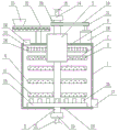
Fig. 1 is a schematic structural diagram of the present invention.
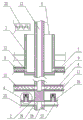
Fig. 2 is an axial sectional view of the middle rotating shaft of the present invention.
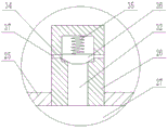
Fig. 3 is an enlarged schematic view at a in fig. 2.
In the figure: 1 tank body, 2 rotating shafts, 3 feeding cylinders, 4 stirring rods, 5 first bearings, 6 feeding ports, 7 material dividing rods, 8 solid material feeding cavities, 9 solid material feeding holes, 10 liquid material feeding cavities, 11 liquid material feeding holes, 12 first grooves, 13 first connecting holes, 14 first rotating joints, 15 liquid material feeding pipes, 16 second bearings, 17 mixture discharging pipes, 18 driving motors, 19 driving wheels, 20 driven wheels, 21 driving belts, 22 spiral conveyors, 23 hoppers, 24 gas discharging pipes, 25 bubbling disks, 26 bubbling nozzles, 27 bubbling cavities, 28 second grooves, 29 second connecting holes, 30 second rotating joints, 31 compressed air inlet pipes, 32 third grooves, 33 defoaming teeth, 34 annular steps, 35 springs, 36 anti-blocking circular tables, 37 bubbling holes and 38 defoaming rods.
Detailed Description
The embodiments of the present invention will be further explained with reference to the drawings.
Referring to fig. 1-3, a compounding device, including the columniform jar body 1, jar internal being equipped with rather than coaxial pivot 2, pivot 2 is connected with actuating mechanism, is equipped with feed cylinder 3 and puddler 4 from last to being equipped with down in proper order in pivot 2, the coaxial outside of pivot 2 of locating of feed cylinder 3, and feed cylinder 3 rotates with jar body 1 through first bearing 5 to be connected, and feed cylinder 3 top extends to jar body 1 outside and is equipped with feed inlet 6, and feed inlet 6 top is equipped with solid-state material feeding mechanism, and feed cylinder 3 bottom is fixed in pivot 2, is equipped with 2 on the outer peripheral face of feed cylinder 3 bottom and divides material pole 7, is equipped with solid-state material feeding chamber 8 and solid-state material feed port 9 on dividing material pole 7, solid-state material feeding chamber 8 and the inside intercommunication of feed cylinder 3, solid-state material feed port 9 is a plurality of and communicates with solid-state material feeding. The stirring rod 4 is provided with a liquid material feeding cavity 10 and a liquid material feeding hole 11, and the liquid material feeding hole 11 is multiple and is communicated with the liquid material feeding cavity 10. 2 upper portions of pivot are equipped with ascending first recess 12 of opening, first recess 12 is through first through-hole 13 and puddler 4 on liquid material feeding chamber 10 intercommunication, the top of pivot 2 is run through a feeding section of thick bamboo 3 and is extended to the jar body 1 outside and be connected with first rotary joint 14, the access connection of first rotary joint 14 has liquid material inlet pipe 15 and its export and first recess 12 intercommunication, the bottom of pivot 2 is passed through second bearing 16 and is connected with jar body 1 rotation, jar body 1 bottom is equipped with mixture discharging pipe 17.
The driving mechanism comprises a driving motor 18, a driving wheel 19, a driven wheel 20 and a transmission belt 21, the driving motor 18 is fixed at the top of the tank body 1, the driving wheel 19 is connected with the driving motor 18, the driven wheel 20 is coaxially fixed at the outer side of the rotating shaft 2, and the driving wheel 19 and the driven wheel 20 are connected through the transmission belt 21.
The solid material feeding mechanism comprises a spiral conveyor 22 and a hopper 23, the spiral conveyor 22 is fixed at the top of the tank body 1, the discharge end of the spiral conveyor 22 is arranged above the feed inlet 6 of the feed cylinder 3, and the hopper 23 is arranged at the feed end of the spiral conveyor 22 and communicated with the interior of the spiral conveyor 22.
The gas discharge pipe 24 is arranged on the tank body 1, the bubbling mechanism is arranged at the bottom in the tank body 1, the bubbling mechanism comprises a bubbling tray 25 and a bubbling spray head 26, the bubbling tray 25 is coaxially fixed on the outer side of the rotating shaft 2, a bubbling cavity 27 is arranged on the bubbling tray 25, the bubbling spray head 26 is a plurality of and is arranged on the bubbling tray 25, the bubbling spray head 26 is communicated with the bubbling cavity 27, the lower part of the rotating shaft 2 is provided with a second groove 28 with a downward opening, the second groove 28 is communicated with the bubbling cavity 27 through a second communication hole 29, the bottom end of the rotating shaft 2 extends to the outer side of the tank body 1 and is connected with a second rotary joint 30, and the inlet of the second rotary joint 30 is connected with a compressed air inlet pipe. Compressed air enters the bubbling cavity 27 of the bubbling tray 25 from the second rotary joint 30 and is sprayed out from the bubbling nozzle 26 to stir and mix the materials at the bottom of the tank body 1, so that the materials are prevented from being accumulated at the bottom of the tank body 1 to cause uneven mixing. The second groove 28 is not in communication with the first groove 12.
Be equipped with the third recess 32 with tympanic bulla chamber 27 intercommunication in the tympanic bulla shower nozzle 26, be equipped with annular step 34 in the third recess 32 and the diameter at third recess 32 tank bottom is greater than the diameter of opening part, and third recess 32 tank bottom department is connected with anti-blocking round platform 36 through spring 35, is equipped with the drum bubble 37 on the tympanic bulla shower nozzle 26, drum bubble 37 is located on the lateral wall between third recess 32 tank bottom and the annular step 24. After the compressed air enters the third groove 32 of the bubbling nozzle 26, the pressure of the compressed air on the anti-blocking circular truncated cone 36 overcomes the self-gravity and the elastic force of the spring 35 and moves towards the bottom of the groove, so that the bubbling hole 37 is communicated with the third groove 32, and the compressed air enters the tank body 1 through the bubbling hole 37 to form bubbling. The bubbling stirs the contents of the tank 1 and discharges them from the gas discharge pipe 24. When compressed air is not introduced into the bubbling nozzle 26, the anti-blocking circular truncated cone 36 is clamped at the annular step 24 under the action of gravity, so that the bubbling hole 37 is blocked, and the bubbling nozzle 26 is prevented from being blocked by materials in the tank body 1.
A defoaming rod 38 is arranged in the tank body 1, and the defoaming rod 38 is fixed on the outer peripheral surface of the feeding cylinder 3 and is provided with defoaming teeth 33. The defoaming teeth 33 on the defoaming bar 38 can break the surface tension of the bubbles to break the bubbles, thereby preventing the materials in the tank body 1 from being discharged along with the bubbles.
During material mixing, the driving motor 18 drives the rotating shaft 2 to rotate, and the feeding cylinder 3, the stirring rod 4 and the bubbling disc 25 which are connected with the rotating shaft 2 rotate along with the rotating shaft 2. The solid material is fed from the hopper 23 to the feeding cylinder 3 through the screw conveyor 22, enters the solid material feeding cavity 8 of the material distributing rod 7 under the action of centrifugal force, and finally enters the tank body 1 through the solid material feeding hole 9. The liquid material enters the first groove 12 from the liquid material feeding pipe 15 through the first rotary joint 14, enters the liquid material feeding cavity 10 of the stirring rod 4 through the first communication hole 13, and finally enters the tank body 1 through the liquid material feeding hole 11. After the solid material and the liquid material fall into the tank body 1, the solid material and the liquid material are stirred and fully mixed under the action of the stirring rod 4 and the bubbling mechanism, so that the purpose of mixing materials is achieved. When the solid material and the liquid material enter the tank body 1, the solid material and the liquid material are uniformly dispersed in the tank body 1 through the material distributing rod 7 and the stirring rod 4, so that the contact area between the solid material and the liquid material is increased, the wetting of the solid material is facilitated, the stirring time is shortened, and the efficiency and the effect of solid-liquid mixing are improved. And after the material mixing is finished, discharging the mixed material from a mixed material discharging pipe 17.
The utility model discloses in, the mixture of material in jar body 1 is accomplished through the dual stirring of puddler 4 and bubbling mechanism, thereby wherein puddler 4 can carry out radial stirring to the material and produce radial flow, thereby bubbling mechanism can carry out axial stirring to the material and produce axial flow, and puddler 4 and bubbling mechanism cooperate the shearing force big, and the dispersion is strong, can carry out abundant efficient compounding to the material.
Claims (6)
1. The utility model provides a compounding device, includes the columniform jar body, its characterized in that: the feeding device comprises a tank body, a feeding cylinder, a stirring rod, a first bearing, a driving mechanism, a solid material feeding mechanism, a plurality of solid material feeding holes and a second bearing, wherein the tank body is internally provided with a rotating shaft which is coaxial with the tank body, the rotating shaft is connected with the driving mechanism, the rotating shaft is sequentially provided with the feeding cylinder and the stirring rod from top to bottom, the feeding cylinder is coaxially arranged on the outer side of the rotating shaft, the feeding cylinder is rotatably connected with the tank body through the first bearing, the top of the feeding cylinder extends to the outer side of the tank body and is provided with the feeding hole, the solid material feeding mechanism is arranged above the feeding hole, the bottom of the feeding cylinder is fixed on the rotating shaft; be equipped with liquid material feeding chamber and liquid material feed port on the puddler, liquid material feed port be a plurality of and with liquid material feeding chamber intercommunication, pivot upper portion is equipped with the ascending first recess of opening, first recess is through the liquid material feeding chamber intercommunication on first intercommunicating pore and the puddler, the top of pivot is run through a feeding section of thick bamboo and is extended to the external side of jar and be connected with first rotary joint, the access connection of first rotary joint has liquid material inlet pipe and its export and first recess intercommunication, the bottom of pivot is passed through the second bearing and is connected with jar rotation, jar body bottom is equipped with the mixture discharging pipe.
2. A mixing device according to claim 1, characterized in that: the driving mechanism comprises a driving motor, a driving wheel, a driven wheel and a transmission belt, the driving motor is fixed at the top of the tank body, the driving wheel is connected with the driving motor, the driven wheel is coaxially fixed at the outer side of the rotating shaft, and the driving wheel is connected with the driven wheel through the transmission belt.
3. A mixing device according to claim 1, characterized in that: the solid material feeding mechanism comprises a screw conveyor and a hopper, the screw conveyor is fixed at the top of the tank body, the discharge end of the screw conveyor is arranged above the feed inlet of the feed cylinder, and the hopper is arranged at the feed end of the screw conveyor and communicated with the inside of the screw conveyor.
4. A mixing device according to claim 1, characterized in that: the utility model discloses a bubble dish, including the pivot outside, the pivot is equipped with the tympanic bulla chamber, and the bottom is equipped with the tympanic bulla mechanism on jar internal bottom, the tympanic bulla mechanism includes tympanic bulla dish and tympanic bulla shower nozzle, the tympanic bulla dish coaxial fixation in is equipped with the tympanic bulla chamber on the tympanic bulla dish, on the tympanic bulla shower nozzle just locates the tympanic bulla dish for a plurality of, tympanic bulla shower nozzle and tympanic bulla chamber intercommunication, the pivot lower part is equipped with the second recess that the opening is decurrent, and the second recess passes through second intercommunicating pore and tympanic bulla chamber, and the bottom of pivot extends to the external side of jar and is connected.
5. A mixing device as claimed in claim 4, characterized in that: the bubbling nozzle is internally provided with a third groove communicated with the bubbling cavity, the third groove is internally provided with an annular step, the diameter of the bottom of the third groove is larger than that of the opening, the bottom of the third groove is connected with an anti-blocking round table through a spring, the bubbling nozzle is provided with a bubbling hole, and the bubbling hole is arranged on the side wall between the bottom of the third groove and the annular step.
6. A mixing device as claimed in claim 4, characterized in that: the tank body is internally provided with a defoaming rod which is fixed on the peripheral surface of the feeding cylinder and is provided with defoaming teeth.
Priority Applications (1)
| Application Number | Priority Date | Filing Date | Title |
|---|---|---|---|
| CN201920942423.3U CN210544575U (en) | 2019-06-21 | 2019-06-21 | Material mixing device |
Applications Claiming Priority (1)
| Application Number | Priority Date | Filing Date | Title |
|---|---|---|---|
| CN201920942423.3U CN210544575U (en) | 2019-06-21 | 2019-06-21 | Material mixing device |
Publications (1)
| Publication Number | Publication Date |
|---|---|
| CN210544575U true CN210544575U (en) | 2020-05-19 |
Family
ID=70669995
Family Applications (1)
| Application Number | Title | Priority Date | Filing Date |
|---|---|---|---|
| CN201920942423.3U Expired - Fee Related CN210544575U (en) | 2019-06-21 | 2019-06-21 | Material mixing device |
Country Status (1)
| Country | Link |
|---|---|
| CN (1) | CN210544575U (en) |
Cited By (1)
| Publication number | Priority date | Publication date | Assignee | Title |
|---|---|---|---|---|
| CN119407987A (en) * | 2025-01-07 | 2025-02-11 | 山西双慧钢化玻璃股份有限公司 | A device and process for manufacturing repair paste for lost foam |
-
2019
- 2019-06-21 CN CN201920942423.3U patent/CN210544575U/en not_active Expired - Fee Related
Cited By (1)
| Publication number | Priority date | Publication date | Assignee | Title |
|---|---|---|---|---|
| CN119407987A (en) * | 2025-01-07 | 2025-02-11 | 山西双慧钢化玻璃股份有限公司 | A device and process for manufacturing repair paste for lost foam |
Similar Documents
| Publication | Publication Date | Title |
|---|---|---|
| CN111328907B (en) | Chocolate kernel mixing and pouring device | |
| CN205397069U (en) | Prevent blockking up fodder conveyor | |
| CN105965711A (en) | Plastic particle mixing device | |
| CN201375884Y (en) | Horizontal solid-liquid mixing device | |
| CN210357028U (en) | Powder coating mixer | |
| CN218833634U (en) | Decoloration jar is used in gluconolactone preparation | |
| CN210732823U (en) | Even mortar storage tank of unloading | |
| CN108689184B (en) | Vertical powder feeder | |
| CN210758551U (en) | Mixing machine | |
| CN208377095U (en) | A kind of packing machine cutting agency | |
| CN217410387U (en) | Powder-liquid dispersion mixing device | |
| CN216605039U (en) | High-capacity efficient square conical mixer | |
| CN205496496U (en) | Clay sand roller mill | |
| CN117225236A (en) | Raw material mixing device for suspending agent pesticide production | |
| CN110252225B (en) | A mixer for producing low-density polyurethane composite materials | |
| CN204217849U (en) | A kind of combined feed Additive Production device | |
| CN211189881U (en) | A mixer for EVA film production | |
| CN210410689U (en) | Mixing machine for producing low-density polyurethane composite material | |
| CN208757517U (en) | A kind of feed stuff agitating device | |
| CN224257424U (en) | Ru Ciyou charging bucket capable of preventing layering | |
| CN213084203U (en) | Multistage anti-arch vibration discharging device | |
| CN219897700U (en) | Mixing arrangement is used in animal remedy production | |
| CN222384591U (en) | Vertical molasses mixer | |
| CN206343169U (en) | The aqueous polyurethane reactor of automatic uniform charging | |
| CN206381877U (en) | One kind caking self-cleaning type mixing auger |
Legal Events
| Date | Code | Title | Description |
|---|---|---|---|
| GR01 | Patent grant | ||
| GR01 | Patent grant | ||
| CF01 | Termination of patent right due to non-payment of annual fee | ||
| CF01 | Termination of patent right due to non-payment of annual fee |
Granted publication date: 20200519 |