CN210528385U - Easy-to-use building electrical construction installation device - Google Patents
Easy-to-use building electrical construction installation device Download PDFInfo
- Publication number
- CN210528385U CN210528385U CN201921520784.5U CN201921520784U CN210528385U CN 210528385 U CN210528385 U CN 210528385U CN 201921520784 U CN201921520784 U CN 201921520784U CN 210528385 U CN210528385 U CN 210528385U
- Authority
- CN
- China
- Prior art keywords
- fixedly connected
- vertical
- protective cover
- driving mechanism
- lead screw
- Prior art date
- Legal status (The legal status is an assumption and is not a legal conclusion. Google has not performed a legal analysis and makes no representation as to the accuracy of the status listed.)
- Expired - Fee Related
Links
- 238000010276 construction Methods 0.000 title claims abstract description 20
- 238000009434 installation Methods 0.000 title claims abstract description 16
- 230000001681 protective effect Effects 0.000 claims abstract description 24
- 239000002893 slag Substances 0.000 claims abstract description 14
- WABPQHHGFIMREM-UHFFFAOYSA-N lead(0) Chemical compound [Pb] WABPQHHGFIMREM-UHFFFAOYSA-N 0.000 claims description 2
- 239000000428 dust Substances 0.000 abstract description 5
- 238000000034 method Methods 0.000 description 3
- 239000013049 sediment Substances 0.000 description 2
- 230000009286 beneficial effect Effects 0.000 description 1
- 238000009792 diffusion process Methods 0.000 description 1
- 238000010616 electrical installation Methods 0.000 description 1
- 238000004519 manufacturing process Methods 0.000 description 1
Images

Landscapes
- Earth Drilling (AREA)
Abstract
The utility model discloses an easy-to-use building electrical construction installation device, which comprises a protective cover and a scraper; the scraper is connected with a driving mechanism through a cutter bar, the lower end of the protective cover is fixedly connected with a supporting rod, the outer side of the protective cover is fixedly connected with a holding rod, and the holding rod is fixedly connected with a switch panel. The utility model realizes the reciprocating hole digging operation of the scraper and collects the crushed slag and the dust by arranging the protective cover with the slag discharge pipe, the limiting plate with the longitudinal sliding groove and the guide rod, the sliding strip, the eccentric column and the eccentric disc; the feeding and the up-and-down movement of the scraper are realized through the arrangement of the horizontal driving mechanism comprising the horizontal screw rod and the vertical driving mechanism comprising the vertical screw rod, so that the automatic hole digging operation is realized, and the operation is simple; through being equipped with the telescopic bracing piece, realize the fixed of device, improve and draw the stability of hole operation, replace the manual work to grip and lift.
Description
Technical Field
The utility model relates to an electrical construction equipment field specifically is an easy-to-use type building electrical construction installation device.
Background
In electric construction process, often need draw the hole operation to the wall, and then make things convenient for electric elements's installation, traditional draw the hole device, need draw the hole device, produce more dust and need lift the mobile device in the operation process, operate inconvenient and hard.
SUMMERY OF THE UTILITY MODEL
An object of the utility model is to provide an easy-to-use type building electrical construction installation device to solve the problem that proposes among the above-mentioned background art.
In order to achieve the above object, the utility model provides a following technical scheme:
an easy-to-use building electrical construction installation device comprises a protective cover and a scraper; the scraper is connected with a driving mechanism through a cutter bar, the lower end of the protective cover is fixedly connected with a supporting rod, the outer side of the protective cover is fixedly connected with a holding rod, and the holding rod is fixedly connected with a switch panel.
As a further aspect of the present invention: the driving mechanism comprises a moving frame, a cutter bar penetrates through the moving frame and extends into the moving frame, and the moving frame is of a rectangular box body structure; the cutter bar is fixedly connected with a sliding strip, the sliding strip is a strip-shaped block, the upper end and the lower end of the sliding strip are in sliding connection with the moving frame, the inner wall of the moving frame is provided with a sliding groove matched with the sliding strip, the outer end face of the sliding strip is provided with a vertical groove, an eccentric column is nested in the vertical groove, and the eccentric column is in sliding connection with the vertical groove; the eccentric column is fixedly connected with an eccentric disc, the eccentric disc is fixedly connected with an output shaft of a driving motor, and the driving motor is nested in the movable frame and is electrically connected with an external power supply through a wire.
As a further aspect of the present invention: a limiting plate is fixedly connected in the moving frame, a longitudinal sliding groove is formed in the limiting plate, the cutter bar penetrates through the longitudinal sliding groove and is in sliding connection with the longitudinal sliding groove, and a rectangular through groove opposite to the longitudinal sliding groove is formed in the outer wall of the moving frame; a guide rod is fixedly connected in the longitudinal sliding groove and penetrates through the cutter bar.
As a further aspect of the present invention: the movable rack is connected with a horizontal driving mechanism, the horizontal driving mechanism comprises a lifting rack abutted against the movable rack, a horizontal moving block is fixedly connected to the lower end of the movable rack, the horizontal moving block penetrates through and is in threaded connection with a horizontal lead screw, the horizontal lead screw is connected with an output shaft of a horizontal lead screw motor, and the horizontal lead screw is fixedly connected with the lifting rack and is electrically connected with an external power supply through a lead.
As a further aspect of the present invention: the lifting frame is connected with a vertical driving mechanism, the vertical driving mechanism comprises a vertical moving block fixedly connected with the lifting frame, the vertical moving block penetrates through and is in threaded connection with a vertical lead screw, the vertical lead screw extends to the outer side of the protective cover and is connected with a vertical lead screw motor, and the vertical lead screw motor is electrically connected with an external power supply; the lower end of the protective cover is communicated with a slag discharge pipe.
As a further aspect of the present invention: the support rod is a telescopic rod and is provided with a locking bolt.
Compared with the prior art, the beneficial effects of the utility model are that: the utility model realizes the reciprocating hole digging operation of the scraper and collects the crushed slag and the dust by arranging the protective cover with the slag discharge pipe, the limiting plate with the longitudinal sliding groove and the guide rod, the sliding strip, the eccentric column and the eccentric disc; the feeding and the up-and-down movement of the scraper are realized through the arrangement of the horizontal driving mechanism comprising the horizontal screw rod and the vertical driving mechanism comprising the vertical screw rod, so that the automatic hole digging operation is realized, and the operation is simple; through being equipped with the telescopic bracing piece, realize the fixed of device, improve and draw the stability of hole operation, replace the manual work to grip and lift.
Drawings
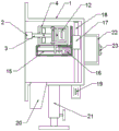
FIG. 1 is a perspective view of an easy-to-use construction electrical installation apparatus;
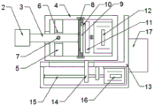
FIG. 2 is a schematic view showing an internal structure of the easy-to-use installation apparatus for electrical construction of buildings;
fig. 3 is a schematic view of a connection structure of a moving frame in the easy-to-use type construction electrical construction installation apparatus.
In the figure: 1-a protective cover; 2-a scraper; 3, cutting a cutter bar; 4-a moving rack; 5-a limiting plate; 6-longitudinal sliding chute; 7-a guide rod; 8-a slide bar; 9-vertical groove; 10-eccentric column; 11-eccentric disc; 12-a drive motor; 13-a lifting frame; 14-a horizontal moving block; 15-horizontal lead screw; 16-a horizontal screw motor; 17-a vertical moving block; 18-a vertical screw rod; 19-a vertical screw motor; 20-a slag discharge pipe; 21-a support bar; 22-a holding rod; 23-switch panel.
Detailed Description
The technical solutions in the embodiments of the present invention will be described clearly and completely with reference to the accompanying drawings in the embodiments of the present invention, and it is obvious that the described embodiments are only some embodiments of the present invention, not all embodiments. Based on the embodiments in the present invention, all other embodiments obtained by a person skilled in the art without creative work belong to the protection scope of the present invention.
Example 1
Referring to fig. 1-3, in an embodiment of the present invention, an easy-to-use installation device for building electrical construction includes a protective cover 1 and a scraper 2; the scraper 2 is connected with a driving mechanism through a cutter bar 3, the driving mechanism comprises a movable frame 4, the cutter bar 3 penetrates through the movable frame 4 and extends into the movable frame 4, and the movable frame 4 is of a rectangular box structure; the cutter bar 3 is fixedly connected with a sliding strip 8, the sliding strip 8 is a strip-shaped block, the upper end and the lower end of the sliding strip are in sliding connection with the movable frame 4, the inner wall of the movable frame 4 is provided with a sliding groove matched with the sliding strip 8, the outer end face of the sliding strip 8 is provided with a vertical groove 9, an eccentric column 10 is embedded in the vertical groove 9, and the eccentric column 10 is in sliding connection with the vertical groove 9; eccentric post 10 fixedly connected with eccentric disc 11, 11 fixedly connected with driving motor 12's of eccentric disc output shaft, driving motor 12 nestification are in removing frame 4 and through wire and external power source electric connection, and driving motor 12 drives eccentric disc 11 and rotates, and eccentric disc 11 drives the vertical reciprocating motion of slip strip 8 through eccentric post 10, and slip strip 8 drives 2 vertical reciprocating motion of scraper through cutter arbor 3, realizes drawing the hole operation to the wall.
A limiting plate 5 is fixedly connected in the moving frame 4, a longitudinal sliding groove 6 is formed in the limiting plate 5, the cutter bar 3 penetrates through the longitudinal sliding groove 6 and is in sliding connection with the longitudinal sliding groove 6, and a rectangular through groove opposite to the longitudinal sliding groove 6 is formed in the outer wall of the moving frame 4; the inside fixedly connected with guide bar 7 of vertical spout 6, guide bar 7 runs through cutter arbor 3 for scraper 2 has better stability.
The horizontal driving mechanism is connected with the moving frame 4 and comprises a lifting frame 13 abutted against the moving frame 4, a horizontal moving block 14 is fixedly connected to the lower end of the moving frame 4, the horizontal moving block 14 penetrates through and is in threaded connection with a horizontal lead screw 15, the horizontal lead screw 15 is connected with an output shaft of a horizontal lead screw motor 16, and the horizontal lead screw 15 is fixedly connected with the lifting frame 13 and is electrically connected with an external power supply through a lead wire; the horizontal screw motor 16 drives the horizontal screw 15 to rotate, further drives the horizontal moving block 14 to move transversely, further drives the moving frame 4 to move transversely, further can control the feeding depth of the scraper 2, further conveniently controls the depth of the hole, and is convenient to operate.
Example 2
This example differs from example 1 in that: the automatic hole digging device is characterized in that the lifting frame 13 is connected with a vertical driving mechanism, the vertical driving mechanism comprises a vertical moving block 17 fixedly connected with the lifting frame 13, the vertical moving block 17 is penetrated through and is in threaded connection with a vertical lead screw 18, the vertical lead screw 18 extends to the outer side of the protective cover 1 and is connected with a vertical lead screw motor 19, the vertical lead screw motor 19 is electrically connected with an external power supply, the vertical lead screw motor 19 drives the vertical lead screw 18 to rotate, the vertical lead screw 18 drives the vertical moving block 17 and the lifting frame 13 to move up and down, then automatic hole digging is achieved, the whole device does not need to be.
The lower end of the protective cover 1 is communicated with a slag discharge pipe 20 for uniformly collecting the crushed slag; the lower end of the protective cover 1 is fixedly connected with a supporting rod 21, the supporting rod 21 is a telescopic rod and is provided with a locking bolt, the height of the whole device is conveniently adjusted, manual holding and lifting are not needed, and the construction stability is improved.
The outer side of the protective cover 1 is fixedly connected with a holding rod 22, the holding rod 22 is fixedly connected with a switch panel 23, and the switch panel 23 is electrically connected with the driving motor 12, the horizontal screw rod motor 16 and the vertical screw rod motor 19 through wires respectively, so that the protective cover is convenient to start.
The utility model discloses a theory of operation: after the position of the hole is dug to the affirmation, the height of the adjusting support rod 21 is fixed through the locking bolt, make protection casing 1 and wall butt, both hands grip holding rod 22, start driving motor 12 through switch panel 23, horizontal lead screw motor 16 and vertical lead screw motor 19, driving motor 12 drives the vertical reciprocating motion of scraper, horizontal lead screw motor 16 drives scraper 2 and advances to the wall body in, vertical lead screw motor 19 drives the scraper and reciprocates simultaneously, need not manual mobile device, realize automatic hole operation of drawing, easy operation is laborsaving, the disintegrating slag that produces is discharged through row sediment pipe 20, can prevent that the disposal bag from collecting the disintegrating slag below row sediment pipe 20, the dust of drawing the in-process production is covered by protection casing 1 and is avoided the diffusion, the protection workman is healthy.
The following are specifically mentioned: in the application, a scraper rod and a driving motor are in the prior art; the protective cover provided with the slag discharge pipe, the limiting plate provided with the longitudinal sliding groove and the guide rod, the sliding strip, the eccentric column, the eccentric disc, the horizontal driving mechanism comprising the horizontal screw rod, the vertical driving mechanism comprising the vertical screw rod and the support rod are innovation points of the application; the reciprocating hole digging operation of the scraper is realized and crushed slag and dust are collected through the protective cover with the slag discharge pipe, the limiting plate with the longitudinal sliding groove and the guide rod, the sliding strip, the eccentric column and the eccentric disc; the feeding and the up-and-down movement of the scraper are realized through the arrangement of the horizontal driving mechanism comprising the horizontal screw rod and the vertical driving mechanism comprising the vertical screw rod, so that the automatic hole digging operation is realized, and the operation is simple; through being equipped with the telescopic bracing piece, realize the fixed of device, improve and draw the stability of hole operation, replace the manual work to grip and lift.
It is obvious to a person skilled in the art that the invention is not restricted to details of the above-described exemplary embodiments, but that it can be implemented in other specific forms without departing from the spirit or essential characteristics of the invention. The present embodiments are therefore to be considered in all respects as illustrative and not restrictive, the scope of the invention being indicated by the appended claims rather than by the foregoing description, and all changes which come within the meaning and range of equivalency of the claims are therefore intended to be embraced therein. Any reference sign in a claim should not be construed as limiting the claim concerned.
Furthermore, it should be understood that although the present description refers to embodiments, not every embodiment may contain only a single embodiment, and such description is for clarity only, and those skilled in the art should integrate the description, and the embodiments may be combined as appropriate to form other embodiments understood by those skilled in the art.
Claims (6)
1. An easy-to-use building electrical construction installation device comprises a protective cover (1) and a scraper (2); the scraper is characterized in that the scraper (2) is connected with a driving mechanism through a cutter bar (3), the lower end of the protective cover (1) is fixedly connected with a supporting rod (21), the outer side of the protective cover (1) is fixedly connected with a holding rod (22), and the holding rod (22) is fixedly connected with a switch panel (23).
2. The easy-to-use type building electrical construction installation device is characterized in that the driving mechanism comprises a movable frame (4), the cutter bar (3) penetrates through the movable frame (4) and extends into the movable frame (4), and the movable frame (4) is of a rectangular box structure; the cutter bar (3) is fixedly connected with a sliding strip (8), the sliding strip (8) is a strip-shaped block, the upper end and the lower end of the sliding strip are in sliding connection with the moving frame (4), a sliding groove matched with the sliding strip (8) is formed in the inner wall of the moving frame (4), a vertical groove (9) is formed in the outer end face of the sliding strip (8), an eccentric column (10) is nested in the vertical groove (9), and the eccentric column (10) is in sliding connection with the vertical groove (9); the eccentric column (10) is fixedly connected with an eccentric disc (11), the eccentric disc (11) is fixedly connected with an output shaft of a driving motor (12), and the driving motor (12) is nested in the movable frame (4) and is electrically connected with an external power supply through a lead.
3. The easy-to-use building electrical construction installation device according to claim 2, wherein a limiting plate (5) is fixedly connected in the moving frame (4), the limiting plate (5) is provided with a longitudinal sliding groove (6), the cutter bar (3) penetrates through the longitudinal sliding groove (6) and is in sliding connection with the longitudinal sliding groove (6), and the outer wall of the moving frame (4) is provided with a rectangular through groove opposite to the longitudinal sliding groove (6); a guide rod (7) is fixedly connected in the longitudinal sliding groove (6), and the guide rod (7) penetrates through the cutter bar (3).
4. The easy-to-use building electrical construction installation device according to claim 2, wherein the moving frame (4) is connected with a horizontal driving mechanism, the horizontal driving mechanism comprises a lifting frame (13) abutted against the moving frame (4), a horizontal moving block (14) is fixedly connected to the lower end of the moving frame (4), the horizontal moving block (14) penetrates through and is in threaded connection with a horizontal lead screw (15), the horizontal lead screw (15) is connected with an output shaft of a horizontal lead screw motor (16), and the horizontal lead screw (15) is fixedly connected with the lifting frame (13) and is electrically connected with an external power supply through a lead wire.
5. The easy-to-use building electrical construction installation device is characterized in that the lifting frame (13) is connected with a vertical driving mechanism, the vertical driving mechanism comprises a vertical moving block (17) fixedly connected with the lifting frame (13), the vertical moving block (17) penetrates through and is in threaded connection with a vertical lead screw (18), the vertical lead screw (18) extends to the outer side of the protective cover (1) and is connected with a vertical lead screw motor (19), and the vertical lead screw motor (19) is electrically connected with an external power supply; the lower end of the protective cover (1) is communicated with a slag discharge pipe (20).
6. An easy-to-use installation device for electrical construction of buildings according to claim 1, characterized in that the support rods (21) are telescopic rods and are provided with locking bolts.
Priority Applications (1)
| Application Number | Priority Date | Filing Date | Title |
|---|---|---|---|
| CN201921520784.5U CN210528385U (en) | 2019-09-12 | 2019-09-12 | Easy-to-use building electrical construction installation device |
Applications Claiming Priority (1)
| Application Number | Priority Date | Filing Date | Title |
|---|---|---|---|
| CN201921520784.5U CN210528385U (en) | 2019-09-12 | 2019-09-12 | Easy-to-use building electrical construction installation device |
Publications (1)
| Publication Number | Publication Date |
|---|---|
| CN210528385U true CN210528385U (en) | 2020-05-15 |
Family
ID=70605291
Family Applications (1)
| Application Number | Title | Priority Date | Filing Date |
|---|---|---|---|
| CN201921520784.5U Expired - Fee Related CN210528385U (en) | 2019-09-12 | 2019-09-12 | Easy-to-use building electrical construction installation device |
Country Status (1)
| Country | Link |
|---|---|
| CN (1) | CN210528385U (en) |
-
2019
- 2019-09-12 CN CN201921520784.5U patent/CN210528385U/en not_active Expired - Fee Related
Similar Documents
| Publication | Publication Date | Title |
|---|---|---|
| CN106217243A (en) | A kind of grinding machine with dust exhaust apparatus | |
| CN210201266U (en) | Electric automatization uses electric cabinet convenient to remove | |
| CN107756499A (en) | A kind of warming plate cutting machine for being easy to regulation | |
| CN210676771U (en) | Reinforcing steel bar cutting device for tunnel of urban underground space engineering | |
| CN220533101U (en) | A metal pipe cutting device | |
| CN210907889U (en) | Positioner is used in processing of hexagonal net | |
| CN217196232U (en) | Stone bench board cutting machine convenient to it is fixed | |
| CN215279650U (en) | Water conservancy construction is with adjustable bar cutter who cuts off aircraft nose | |
| CN211051143U (en) | Environmental protection dust collecting equipment of building engineering construction | |
| CN215237144U (en) | Perforating device is used in manufacturing of high efficiency space flight material | |
| CN212045161U (en) | Environment-friendly material cutting device | |
| CN218576380U (en) | Cutting device for PET plastic pipe | |
| CN220574791U (en) | Positioning device for scraper conveyor pin rail processing | |
| CN210098810U (en) | Steel bar cutting device for building engineering | |
| CN217620878U (en) | Environment-friendly strip material's perforating device | |
| CN213224607U (en) | Numerical control cutting machine tool capable of stably feeding | |
| CN214737697U (en) | Multifunctional electric sweeper | |
| CN215844099U (en) | Building construction material sieving mechanism convenient to collect | |
| CN215434401U (en) | Perforating device for assembly type building | |
| CN219944459U (en) | Cutting machine for reinforcing steel bar | |
| CN219404484U (en) | Cutting device is used in rail production | |
| CN218699227U (en) | FRP guardrail production cutting device | |
| CN213358573U (en) | Municipal administration pipeline buries underground with bed soil tamping device | |
| CN211110282U (en) | Insulating paper folding mechanism | |
| CN216463623U (en) | Panel corner grinding device is used in building materials processing |
Legal Events
| Date | Code | Title | Description |
|---|---|---|---|
| GR01 | Patent grant | ||
| GR01 | Patent grant | ||
| CF01 | Termination of patent right due to non-payment of annual fee | ||
| CF01 | Termination of patent right due to non-payment of annual fee |
Granted publication date: 20200515 |