CN210523501U - Punch press is used in metal product processing - Google Patents
Punch press is used in metal product processing Download PDFInfo
- Publication number
- CN210523501U CN210523501U CN201920702723.4U CN201920702723U CN210523501U CN 210523501 U CN210523501 U CN 210523501U CN 201920702723 U CN201920702723 U CN 201920702723U CN 210523501 U CN210523501 U CN 210523501U
- Authority
- CN
- China
- Prior art keywords
- connecting plate
- fixedly connected
- spring
- supporting seat
- welded
- Prior art date
- Legal status (The legal status is an assumption and is not a legal conclusion. Google has not performed a legal analysis and makes no representation as to the accuracy of the status listed.)
- Expired - Fee Related
Links
- 239000002184 metal Substances 0.000 title claims abstract description 9
- 238000003825 pressing Methods 0.000 claims description 7
- 230000035939 shock Effects 0.000 abstract description 15
- 230000000694 effects Effects 0.000 abstract description 3
- 230000002035 prolonged effect Effects 0.000 abstract description 3
- 238000004080 punching Methods 0.000 description 13
- 239000000463 material Substances 0.000 description 6
- 238000003466 welding Methods 0.000 description 4
- 238000003754 machining Methods 0.000 description 2
- 238000000034 method Methods 0.000 description 2
- 238000010521 absorption reaction Methods 0.000 description 1
- 230000004075 alteration Effects 0.000 description 1
- 230000009286 beneficial effect Effects 0.000 description 1
- 230000003139 buffering effect Effects 0.000 description 1
- 238000006243 chemical reaction Methods 0.000 description 1
- 230000006835 compression Effects 0.000 description 1
- 238000007906 compression Methods 0.000 description 1
- 230000007547 defect Effects 0.000 description 1
- 230000007774 longterm Effects 0.000 description 1
- 238000004519 manufacturing process Methods 0.000 description 1
- 238000012986 modification Methods 0.000 description 1
- 230000004048 modification Effects 0.000 description 1
- 230000002093 peripheral effect Effects 0.000 description 1
- 238000006467 substitution reaction Methods 0.000 description 1
Images
Landscapes
- Presses And Accessory Devices Thereof (AREA)
Abstract
The utility model discloses a punch press is used in metal product processing, comprising a supporting seat, the fixed drive arrangement that is provided with in top of supporting seat, the first supporting block of equal fixedly connected with all around of inner cavity of a support base bottom, one side swing joint that inner wall of a support seat was kept away from to first supporting block has first connecting plate, the first telescopic link of one side fixedly connected with of first connecting plate, one side fixedly connected with second connecting plate of first connecting plate is kept away from to first telescopic link, the surface cover of first telescopic link is equipped with first spring, the one end of first spring welds with one side of first connecting plate. The utility model discloses a set up the structure cooperation of first supporting shoe, first connecting plate, first telescopic link, second connecting plate, first spring and second supporting shoe, improved the shock attenuation effect of placing the board, improved the shock attenuation nature of punch press machinery, prolonged the life of punch press machinery.
Description
Technical Field
The utility model relates to a punch press technical field specifically is a punch press is used in metal product processing.
Background
The punching machine is a punching press, in the national production, the punching process has the advantages of saving material and energy, high efficiency, low technical requirement on operators and capability of making products which cannot be achieved by machining through various die applications, so that the punching machine has wider and wider application range, the punching machine applies pressure to the material to enable the material to be plastically deformed to obtain the required shape and precision, a group of dies must be matched to place the material in the punching machine, the machine applies pressure to enable the material to be deformed, the reaction force caused by the force applied to the material during machining is required, the defect of insufficient shock absorption is existed due to the shock force absorbed by the mechanical body of the punching machine, and the shock force can damage the machine in the long term, thereby reducing the service life of the machine.
SUMMERY OF THE UTILITY MODEL
An object of the utility model is to provide a punch press is used in metal product processing possesses the advantage that improves punch press shock attenuation nature, has solved the not enough problem of shock attenuation nature of current punch press machinery existence.
In order to achieve the above object, the utility model provides a following technical scheme: the utility model provides a punch press is used in metal product processing, includes the supporting seat, the fixed drive arrangement that is provided with in top of supporting seat, the first supporting shoe of equal fixedly connected with all around of inner cavity of a support base bottom, one side swing joint that supporting seat inner wall was kept away from to first supporting shoe has first connecting plate, the first telescopic link of one side fixedly connected with of first connecting plate, one side fixedly connected with second connecting plate that first connecting plate was kept away from to first telescopic link, the surface cover of first telescopic link is equipped with first spring, the one end of first spring and one side welding of first connecting plate, the other end of first spring and one side welding of second connecting plate, the top fixedly connected with second supporting shoe of second connecting plate, the board is placed to the top fixedly connected with of second supporting shoe.
Preferably, the center of the bottom of the inner cavity of the supporting seat is fixedly connected with a second telescopic rod, a second spring is sleeved on the surface of the second telescopic rod, the top end of the second spring is welded with the bottom of the placing plate, and the bottom end of the second spring is welded with the inner wall of the supporting seat.
Preferably, the driving device comprises a driving box, one side of the driving box is fixedly connected with a driving motor, an output shaft of the driving motor is fixedly connected with a concave rod, a sliding cylinder is sleeved on the surface of the concave rod, a connecting rod is welded at the bottom of the sliding cylinder, a guide pillar is welded at the bottom of an inner cavity of the driving box, and a sleeve is sleeved on the surface of the guide pillar.
Preferably, one side corresponding to the sleeve is welded with a pressing block, and the top of the pressing block is movably connected with the bottom of the connecting rod through a movable shaft.
Preferably, the top of supporting seat has been seted up logical groove, the groove footpath that leads to the groove is greater than the size of placing the board.
Compared with the prior art, the beneficial effects of the utility model are as follows:
1. the utility model discloses a set up the structure cooperation of first supporting shoe, first connecting plate, first telescopic link, second connecting plate, first spring and second supporting shoe, improved the shock attenuation effect of placing the board, improved the shock attenuation nature of punch press machinery, solved current punch press machinery and had the not enough problem of shock attenuation nature, prolonged the life of punch press machinery.
2. The utility model further improves the buffer force by the structural design of the second telescopic rod and the second spring;
through the structural cooperation of the driving motor, the concave rod, the sliding barrel, the connecting rod, the guide pillar and the sleeve, the workpiece on the placing plate can be conveniently stamped;
the groove diameter through the through groove is larger than the size of the placing plate, so that the placing plate can be conveniently displaced during stamping, and damage to the punching machine machinery caused by vibration force is reduced.
Drawings
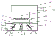
FIG. 1 is a schematic structural view of the present invention;
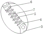
FIG. 2 is an enlarged view of a portion A of FIG. 1;
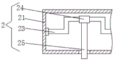
fig. 3 is an internal cross-sectional view of the driving box of the present invention.
In the figure: the device comprises a supporting seat 1, a driving device 2, a driving box 21, a driving motor 22, a concave rod 23, a sliding barrel 24, a connecting rod 25, a guide pillar 26, a sleeve 27, a first supporting block 3, a first connecting plate 4, a first telescopic rod 5, a second connecting plate 6, a first spring 7, a second supporting block 8, a placing plate 9, a second telescopic rod 10, a second spring 11, a pressing block 12 and a through groove 13.
Detailed Description
The technical solutions in the embodiments of the present invention will be described clearly and completely with reference to the accompanying drawings in the embodiments of the present invention, and it is obvious that the described embodiments are only some embodiments of the present invention, not all embodiments. Based on the embodiments in the present invention, all other embodiments obtained by a person skilled in the art without creative work belong to the protection scope of the present invention.
In the description of the present invention, it should be noted that the terms "upper", "lower", "inner", "outer", "front end", "rear end", "both ends", "one end", "the other end", and the like indicate orientations or positional relationships based on the orientations or positional relationships shown in the drawings, and are only for convenience of description and simplification of description, but do not indicate or imply that the device or element to be referred must have a specific orientation, be constructed in a specific orientation, and be operated, and thus, should not be construed as limiting the present invention. Furthermore, the terms "first" and "second" are used for descriptive purposes only and are not to be construed as indicating or implying relative importance.
In the description of the present invention, it is to be noted that, unless otherwise explicitly specified or limited, the terms "mounted", "provided", "connected", and the like are to be construed broadly, such as "connected", which may be fixedly connected, detachably connected, or integrally connected; can be mechanically or electrically connected; they may be connected directly or indirectly through intervening media, or they may be interconnected between two elements. The specific meaning of the above terms in the present invention can be understood in specific cases to those skilled in the art.
Referring to fig. 1-3, a punch press for processing metal products comprises a supporting seat 1, a second telescopic rod 10 is fixedly connected to the center of the bottom of an inner cavity of the supporting seat 1, a second spring 11 is sleeved on the surface of the second telescopic rod 10, the top end of the second spring 11 is welded to the bottom of a placing plate 9, the bottom end of the second spring 11 is welded to the inner wall of the supporting seat 1, the buffering force is further improved by the structural design of the second telescopic rod 10 and the second spring 11, a through groove 13 is formed in the top of the supporting seat 1, the groove diameter of the through groove 13 is larger than the size of the placing plate 9, the placing plate 9 is convenient to displace during punching by setting the groove diameter of the through groove 13 to be larger than the size of the placing plate 9, so that the damage of vibration force to a punch press machine is reduced, a driving device 2 is fixedly arranged on the top of the supporting seat 1, the driving device 2 comprises a driving box 21, the output shaft of the driving motor 22 is fixedly connected with a concave rod 23, the surface of the concave rod 23 is sleeved with a sliding cylinder 24, the bottom of the sliding cylinder 24 is welded with a connecting rod 25, the bottom of the inner cavity of the driving box 21 is welded with a guide pillar 26, the surface of the guide pillar 26 is sleeved with a sleeve 27, one side corresponding to the sleeve 27 is welded with a pressing block 12, the top of the pressing block 12 is movably connected with the bottom of the connecting rod 25 through a movable shaft, through the structural matching of the driving motor 22, the concave rod 23, the sliding cylinder 24, the connecting rod 25, the guide pillar 26 and the sleeve 27, the workpiece on the placing plate 9 is convenient to be punched, the periphery of the inner cavity of the supporting seat 1 is fixedly connected with a first supporting block 3, one side of the first supporting block 3, which is far away from the inner wall of the supporting seat 1, is movably connected with a first connecting plate 4, one side of the first, the surface cover of first telescopic link 5 is equipped with first spring 7, the one end of first spring 7 and one side welding of first connecting plate 4, the other end of first spring 7 and one side welding of second connecting plate 6, the top fixedly connected with second supporting shoe 8 of second connecting plate 6, board 9 is placed to the top fixedly connected with of second supporting shoe 8, through setting up first supporting shoe 3, first connecting plate 4, first telescopic link 5, second connecting plate 6, the structure cooperation of first spring 7 and second supporting shoe 8, the shock attenuation effect of placing board 9 has been improved, the shock attenuation nature of punch press machinery has been improved, the problem that current punch press machinery has shock attenuation nature not enough has been solved, the mechanical life of punch press has been prolonged.
During the use, place the work piece that needs the punching press on placing board 9, make driving motor 22 work through the peripheral hardware controller, driving motor 22 drives spill pole 23 and rotates, spill pole 23 slides on its surface through slide cartridge 24 and drives connecting rod 25 and remove, connecting rod 25 drives briquetting 12 and removes, briquetting 12 slides on guide pillar 26 through sleeve 27 and carries out the punching press to the work piece of placing on board 9, at the in-process of punching press, it can receive the pressure of vibrations to place board 9, at this moment, place board 9 and push second supporting shoe 8, second supporting shoe 8 passes through the first telescopic link 5 of second connecting plate 6 compression, first telescopic link 5 produces the deformation of power through first spring 7, thereby push first connecting plate 4, after the punching press, first spring 7 makes first telescopic link 5 reset, thereby the shock attenuation nature of punch press machinery has been improved.
In summary, the following steps: this punch press for metal product processing through the structure cooperation of first supporting shoe 3, first connecting plate 4, first telescopic link 5, second connecting plate 6, first spring 7 and second supporting shoe 8, has solved the problem that current punch press machinery has the shock attenuation nature not enough.
Although embodiments of the present invention have been shown and described, it will be appreciated by those skilled in the art that changes, modifications, substitutions and alterations can be made in these embodiments without departing from the principles and spirit of the invention, the scope of which is defined in the appended claims and their equivalents.
Claims (5)
1. The utility model provides a punch press for metal product processing, includes supporting seat (1), its characterized in that: the top of the supporting seat (1) is fixedly provided with a driving device (2), the periphery of the bottom of an inner cavity of the supporting seat (1) is fixedly connected with first supporting blocks (3), one side, far away from the inner wall of the supporting seat (1), of each first supporting block (3) is movably connected with a first connecting plate (4), one side of each first connecting plate (4) is fixedly connected with a first telescopic rod (5), one side, far away from the first connecting plate (4), of each first telescopic rod (5) is fixedly connected with a second connecting plate (6), the surface of each first telescopic rod (5) is sleeved with a first spring (7), one end of each first spring (7) is welded with one side of each first connecting plate (4), the other end of each first spring (7) is welded with one side of each second connecting plate (6), the top of each second connecting plate (6) is fixedly connected with a second supporting block (8), and a placing plate (9) is fixedly connected to the top of the second supporting block (8).
2. The press according to claim 1, wherein: the supporting seat is characterized in that a second telescopic rod (10) is fixedly connected to the center of the bottom of an inner cavity of the supporting seat (1), a second spring (11) is sleeved on the surface of the second telescopic rod (10), the top end of the second spring (11) is welded with the bottom of the placing plate (9), and the bottom end of the second spring (11) is welded with the inner wall of the supporting seat (1).
3. The press according to claim 1, wherein: the driving device (2) comprises a driving box (21), a driving motor (22) is fixedly connected to one side of the driving box (21), a concave rod (23) is fixedly connected to an output shaft of the driving motor (22), a sliding barrel (24) is sleeved on the surface of the concave rod (23), a connecting rod (25) is welded to the bottom of the sliding barrel (24), a guide pillar (26) is welded to the bottom of an inner cavity of the driving box (21), and a sleeve (27) is sleeved on the surface of the guide pillar (26).
4. The press according to claim 3, wherein: one side corresponding to the sleeve (27) is welded with a pressing block (12), and the top of the pressing block (12) is movably connected with the bottom of the connecting rod (25) through a movable shaft.
5. The press according to claim 1, wherein: the top of the supporting seat (1) is provided with a through groove (13), and the diameter of the through groove (13) is larger than the size of the placing plate (9).
Priority Applications (1)
| Application Number | Priority Date | Filing Date | Title |
|---|---|---|---|
| CN201920702723.4U CN210523501U (en) | 2019-05-17 | 2019-05-17 | Punch press is used in metal product processing |
Applications Claiming Priority (1)
| Application Number | Priority Date | Filing Date | Title |
|---|---|---|---|
| CN201920702723.4U CN210523501U (en) | 2019-05-17 | 2019-05-17 | Punch press is used in metal product processing |
Publications (1)
| Publication Number | Publication Date |
|---|---|
| CN210523501U true CN210523501U (en) | 2020-05-15 |
Family
ID=70593245
Family Applications (1)
| Application Number | Title | Priority Date | Filing Date |
|---|---|---|---|
| CN201920702723.4U Expired - Fee Related CN210523501U (en) | 2019-05-17 | 2019-05-17 | Punch press is used in metal product processing |
Country Status (1)
| Country | Link |
|---|---|
| CN (1) | CN210523501U (en) |
Cited By (3)
| Publication number | Priority date | Publication date | Assignee | Title |
|---|---|---|---|---|
| CN111834121A (en) * | 2020-07-23 | 2020-10-27 | 深圳市丰宝成科技有限公司 | Automatic material returning and wire pressing package shaping machine for high-frequency transformer |
| CN112145405A (en) * | 2020-09-27 | 2020-12-29 | 苏州旭耀成自动化科技有限公司 | Improved adding pump device |
| CN112935124A (en) * | 2021-02-02 | 2021-06-11 | 赵园 | Plate recycling device for stamping of automobile parts |
-
2019
- 2019-05-17 CN CN201920702723.4U patent/CN210523501U/en not_active Expired - Fee Related
Cited By (3)
| Publication number | Priority date | Publication date | Assignee | Title |
|---|---|---|---|---|
| CN111834121A (en) * | 2020-07-23 | 2020-10-27 | 深圳市丰宝成科技有限公司 | Automatic material returning and wire pressing package shaping machine for high-frequency transformer |
| CN112145405A (en) * | 2020-09-27 | 2020-12-29 | 苏州旭耀成自动化科技有限公司 | Improved adding pump device |
| CN112935124A (en) * | 2021-02-02 | 2021-06-11 | 赵园 | Plate recycling device for stamping of automobile parts |
Similar Documents
| Publication | Publication Date | Title |
|---|---|---|
| CN212070131U (en) | Automobile part stamping die | |
| CN207533785U (en) | A kind of quick quantity-produced Press Tools for Automobiles | |
| CN216096050U (en) | Stamping device is used in machine parts production and processing | |
| CN215032679U (en) | Stamping device convenient to processing of fixed machine parts | |
| CN215748252U (en) | Automatic grinding machanism of cylinder body burr | |
| CN211161396U (en) | Double-station stamping device for circular plate | |
| CN211052247U (en) | A station positioning device for a punch press | |
| CN213997749U (en) | Stamping type metal casting die | |
| CN211018583U (en) | Motor lower bearing crimping tool | |
| CN212144288U (en) | Balance shaft gear bolt forming equipment | |
| CN214919534U (en) | Punching machine is used in mining machinery part production | |
| CN213104137U (en) | Novel two-way riveting mechanism | |
| CN210754712U (en) | Punching die for producing disc type scaffold pressing block | |
| CN211218323U (en) | Die punching device for production of generator stator | |
| CN219335530U (en) | Stamping jig structure | |
| CN223056511U (en) | Auto parts stamping die | |
| CN218638477U (en) | Forging tool | |
| CN219881026U (en) | Stamping device that security performance is high | |
| CN113199191B (en) | Welding device for machining | |
| CN217803543U (en) | Press that has anti-migration function is used in jack production | |
| CN222133325U (en) | A double-die roughing equipment | |
| CN215355748U (en) | An auto parts press with high machining accuracy | |
| CN107598057A (en) | A kind of high-precision forging machine tool | |
| CN213701548U (en) | Forming machine for machining bicycle mudguard | |
| CN215315220U (en) | Punch press capable of fixing punching |
Legal Events
| Date | Code | Title | Description |
|---|---|---|---|
| GR01 | Patent grant | ||
| GR01 | Patent grant | ||
| CF01 | Termination of patent right due to non-payment of annual fee | ||
| CF01 | Termination of patent right due to non-payment of annual fee |
Granted publication date: 20200515 |