High-pressure water curtain machine with adjustable water curtain lower part clearance
Technical Field
The utility model relates to a clear technical field that strains of oil mist specifically is a high pressure water curtain machine with adjustable water curtain lower part clearance.
Background
In the paint spraying operation, a large amount of oil mist is usually generated, which affects the health of personnel and causes environmental pollution. At present, generally, the oil mist is filtered in a cleaning way, air containing the oil mist in a paint spraying room is directly pumped into a barrel filled with liquid medicine solution and is exhausted after the liquid medicine is filtered, the contact area of the liquid medicine and the oil mist is small, the contact time is short, and the oil mist is difficult to be filtered cleanly. Therefore, a special high-pressure water curtain machine is arranged in some paint spray booths to clean and filter oil mist. The water curtain machine among the prior art generally includes pond, basin and cascade, and the splendid attire has the liquid medicine that the oil strain was used in the pond, during operation liquid medicine passes through the pump suction basin, overflows and flows down along the cascade by the one side of basin low level afterwards, forms the liquid medicine layer on the cascade surface, has increased the area of contact of liquid medicine and oil mist, the oil mist in the removal spray booth that can be better. The water curtain machine is provided with a fan and a wind passing cylinder, the lower end of the water curtain is provided with a water retaining block, and the liquid medicine drips on the water retaining block below along the water curtain to generate sputtering, so that the medicine mist is generated. Air in the paint spray booth enters the air passing cylinder through the gap between the lower end of the water curtain and the water retaining block by virtue of the suction of the fan, so that the oil mist and the oil mist further contact and react in the flowing process in the air passing cylinder, and the oil mist is filtered with higher speed.
However, in the existing water curtain machine, the water blocking block at the lower part of the water curtain machine is usually fixedly arranged, the gap between the lower end of the water curtain and the water blocking block is relatively fixed, the density of the medicament in the water curtain machine can be changed due to the use of the liquid medicament, the flow rate of the liquid medicament flowing down along the water curtain can be correspondingly changed, and the fixed gap is not enough to ensure a good filtering effect at any time.
In addition, the oil mist can produce a large amount of filth after being absorbed by the medicament, and if not timely cleaned, the water curtain machine can be adhered to and accumulated too many filths on the whole machine body after being used for a period of time, so that the cleaning is difficult, and the operating environment in a paint spray booth is influenced.
SUMMERY OF THE UTILITY MODEL
An object of the utility model is to overcome prior art's is not enough, provides a high pressure water curtain machine of water curtain machine with adjustable water curtain lower part clearance, can adjust water curtain below manger plate piece according to the liquid medicine condition, keeps better oil mist at any time and strains the effect clearly, when adjusting specific clearance even, the water smoke of its production is under the condition that need not add the liquid medicine, realizes the please of oil mist and strains, whole clean when using simultaneously, clean convenient.
The purpose of the utility model is realized through the following technical scheme:
a high-pressure water curtain machine with an adjustable water curtain lower gap comprises a machine shell and a water pool, wherein the machine shell is fixedly arranged on the water pool, an air passing channel is arranged in the machine shell, a fan is arranged at the top of the machine shell, one end of the air passing channel is arranged above the water pool, the other end of the air passing channel is communicated with an air suction inlet of the fan, a water tank a is arranged on the outer side of the machine shell, a water curtain a is arranged on the overflow side of the water tank a, the lower end of the water curtain a is arranged above the water pool, and the high-pressure water curtain machine further comprises a water pump which is used for pumping liquid medicine in the water pool into the;
the water tank is internally provided with a water retaining block in a sliding manner, an arc-shaped water retaining surface is processed on one side of the water retaining block and is matched with the lower end of the water curtain a, an air inlet is formed between the arc-shaped water retaining surface and the lower end of the water curtain a, and the air inlet is communicated with the air passing channel.
Furthermore, a plurality of slide rails are fixedly arranged on the bottom surface in the water pool, the slide rails are perpendicular to the water curtain a, and a plurality of sliding grooves matched with the slide rails are formed in the bottom surface of the water retaining block.
Furthermore, a plurality of positioning holes are formed in the slide rail in a linear array, the water blocking block is fixedly connected with a mounting plate, mounting holes are machined in the mounting plate, and the mounting plate is fixedly connected with the slide rail through bolts.
Further, it leads dirty board and the dirty groove of collection to set up in the pond, lead dirty one end of board with the top fixed connection of breakwater, it is the inclined plane to lead dirty board, lead dirty other end set up in the notch in the dirty groove of collection, cross the wind passageway and keep away from the one end of fan set up in the notch in the dirty groove of collection, a plurality of intercommunicating pores have been seted up to the lower part in the dirty groove of collection, the intercommunicating pore is used for making the inner chamber in the dirty groove of collection with the inner chamber intercommunication in pond.
Furthermore, the bottom surface of the dirt collecting groove is an inclined plane, and the communication hole is formed in the lower end of the bottom surface of the dirt collecting groove.
Furthermore, a water filtering plate is fixedly arranged at one end, close to the fan, in the air passing channel.
Furthermore, a plurality of arc-shaped plates are fixedly arranged in the casing, the arc-shaped plates are arranged in a staggered mode, and the arc-shaped plates are used for enabling the air passing channel to be an S-shaped channel.
Furthermore, a water tank b is fixedly arranged outside the machine shell, a water curtain b is arranged on the overflow side of the water tank b, the lower end of the water curtain b is arranged in the notch of the water tank a,
the lower part of the water tank is provided with a water outlet and a water outlet, the water outlet is communicated with a stop valve through a pipeline,
one side in pond is provided with the mounting box, and the water pump is fixed set up in the mounting box, the water sucking mouth of water pump with the delivery port passes through the pipeline intercommunication, the delivery outlet of water pump is connected with the pipeline, the other end of pipeline set up in the notch top of basin b.
Furthermore, the bottom surface of the water pool is an inclined plane, and the water outlet are both arranged at the lower end of the bottom surface of the water pool.
The utility model has the advantages that:
1. the high-pressure water curtain machine is compact in structure and high in integration level.
2. Set up slidable manger plate piece below the cascade, one side of manger plate piece sets up the arc manger plate face with cascade lower extreme looks adaptation, can make along with the liquid medicine that the cascade flows down produce suitable medicine fog when dripping through the gliding manger plate piece.
3. The fan and the air passing channel are arranged, so that when the fan runs, oil mist in the paint spray booth and the medicine mist can be sucked into the air passing channel together, the oil mist and the medicine mist are in full contact, and the cleaning efficiency is improved. The air passing channel is internally divided into S-shaped channels by the arc-shaped plates, so that the retention time of oil mist and medicine mist in the air passing channel is prolonged, the contact is more sufficient, and the cleaning and filtering are more efficient.
4. The arrangement of the dirt guide plate and the dirt collecting groove can effectively collect dirt generated by reaction of liquid medicine and oil mist into the dirt collecting groove, and other parts of the water curtain machine are not reached under the action of the water pump, so that the integral cleanness of the water curtain machine during use is ensured, and the operation environment of a paint spraying room is effectively ensured.
5. Set up the drainage board, effectively will be by oil mist or medicine fog and the water smoke filtering that contains in the air of fan extraction, avoid inside it gets into the fan, cause the pollution to the fan, influence its normal use.
Drawings
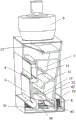
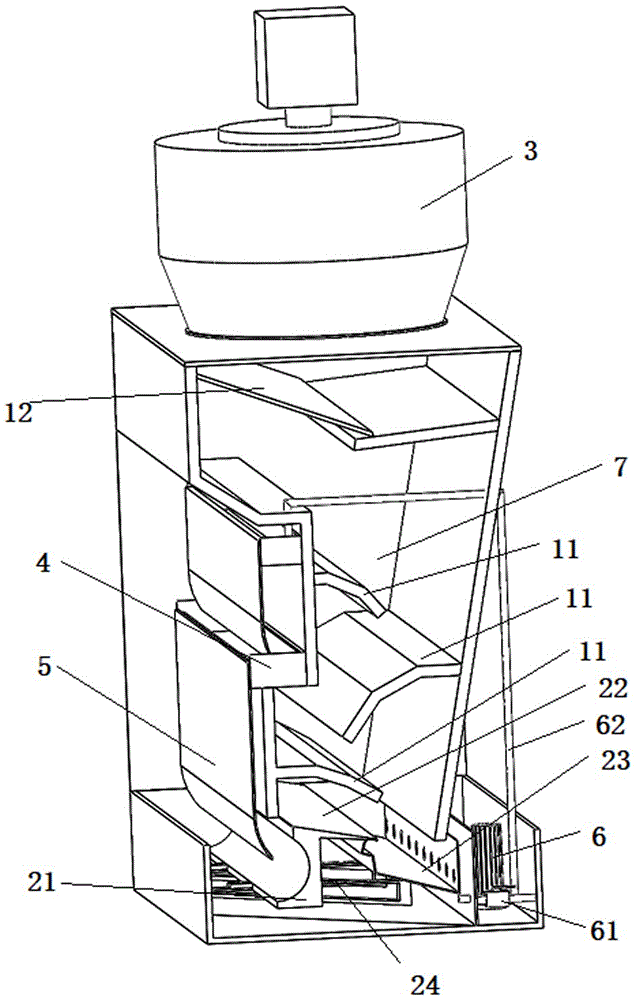
FIG. 1 is a schematic view of the internal structure of a high pressure water curtain machine with adjustable gap at the lower part of the water curtain of the present invention;
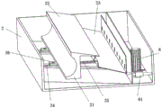
FIG. 2 is a schematic view of the interior of the pool;
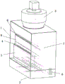
fig. 3 is a schematic view of the overall structure of a high-pressure water curtain machine with adjustable gap at the lower part of the water curtain.
Detailed Description
The technical solution of the present invention is described in further detail below with reference to the accompanying drawings, but the scope of the present invention is not limited to the following description.
As shown in fig. 1 to 3, a high pressure water curtain machine in the prior art includes a housing 1 and a water tank 2, wherein the housing 1 is fixedly disposed on the water tank 2. The outer side of the cabinet 1 is provided with a water tank a4, the overflow side of the water tank a4 is provided with a water curtain a5, and the lower end of the water curtain a5 is arranged above the water tank 2. The water curtain machine is also provided with a water pump 6, when in use, the water curtain machine is arranged in a paint spray booth, the water tank 2 is filled with liquid medicine for filtering oil mist, and the liquid medicine is pumped into the water tank a4 under the action of the water pump 6. One side of the water tank a4 is shorter, when the liquid medicine in the water tank a4 reaches a certain height, the liquid medicine overflows through the shorter side and flows down along the water curtain a5, and a liquid medicine layer is formed on the water curtain a5, so that the contact area between the liquid medicine and the air in the spray booth can be increased, and the effect of removing oil stains better is achieved.
An air passing channel 7 is arranged in the machine shell 1, a fan 3 is arranged at the top of the machine shell 1, one end of the air passing channel 7 is arranged above the water pool 2, and the other end of the air passing channel is communicated with an air suction opening of the fan 3. The liquid medicine on the water curtain a5 can be sputtered to generate medicine when dripping, and the medicine mist and the air in the paint spraying room can be sucked into the air passing channel 7 together under the action of the fan 3, so that the oil mist and the medicine mist in the air are fully mixed, and the effect of better removing the oil mist is achieved. However, the oil mist reacts with the liquid medicine when being filtered by the liquid medicine, dirt is generated in the liquid medicine with the lapse of time, and the concentration of the medicinal agent in the liquid medicine is also reduced. Under the condition that the concentration of the liquid medicine is changed, the liquid medicine is dripped and sputtered before, proper medicine mist is difficult to form, and efficient cleaning and filtering of the oil mist cannot be guaranteed. The water curtain machine in the prior art is usually fixed in structure and cannot adjust the sputtering state, and in order to ensure the filtering effect, the concentration of the liquid medicine needs to be detected at any time to supplement the medicine.
Therefore, the utility model provides a high pressure water curtain machine with adjustable water curtain lower part clearance promptly on current water curtain machine's basis, slidable is provided with breakwater 21 in pond 2, and one side processing of breakwater 21 has the arc manger plate face, and the arc manger plate face is formed with the air intake between the lower extreme of arc manger plate face and water curtain a5 with the lower extreme looks adaptation of water curtain a5, air intake and cross wind channel 7 intercommunication. When the new medicine liquid is used for a period of time and the cleaning and filtering effect is not good, the water retaining block 21 can be adjusted front and back to change the gap at the lower end of the water curtain a5, the arc-shaped water retaining surface is used for receiving water at the lower end of the water curtain a5 to generate sputtering to cause proper amount of medicine mist, so that the air in the paint spray room and the air in the air inlet are sucked into the air passing channel 7 together for contact reaction, and the better cleaning and filtering effect is achieved. In the implementation process, when the gap at the lower end of the water curtain a5 is small enough, the splashed water mist particles generated by the arc water blocking surface matched with the gap are small enough, and the oil mist can be cleaned without adding the liquid medicine.
During the concrete implementation, be provided with a plurality of slide rails 24 on the bottom surface in the pond 2 fixedly, a plurality of slide rails 24 all are perpendicular to cascade a5 setting, and the bottom surface processing of manger plate 21 has a plurality of spouts with slide rail 24 looks adaptation, makes manger plate 21 slide more smoothly through slide rail 24, and slide rail 24 also plays limiting displacement to manger plate 21 is whole simultaneously, makes it be on a parallel with cascade a5 and removes when adjusting. The top of the slide rail 24 is provided with a plurality of positioning holes 25 in a linear array, the water blocking block 21 is fixedly connected with a mounting plate 26, the mounting plate 26 is provided with mounting holes, and the mounting plate 26 is fixedly connected with the slide rail 24 through bolts. After the adjustment is finished, the water blocking block 21 can be fixed by the bolts penetrating through the mounting holes and one of the positioning holes 25, and the adjustment is convenient.
In practice, a water tank b8 is fixedly arranged outside the cabinet 1, a water curtain b9 is arranged on the overflow side of the water tank b8, and the lower end of the water curtain b9 is arranged in the notch of the water tank a 4. The lower part of the water pool 2 is provided with a water outlet and a water outlet, and the water outlet is communicated with a stop valve 61 through a pipeline. One side in pond 2 is provided with the mounting box, and water pump 6 is fixed to be set up in the mounting box, and the mouth that absorbs water and the delivery port of water pump 6 pass through the pipeline intercommunication, and the delivery outlet of water pump 6 is connected with pipeline 62, and the other end of pipeline 62 sets up in basin b 8's notch top. When the water pump 6 is started, the liquid medicine in the water tank 2 can be pumped into the water tank b8 through the pipeline 62, the height of one side plate of the water tank b8 is low, and when a certain amount of liquid medicine is filled in the water tank 8, the liquid medicine overflows from the position of the low side plate and flows into the water tank a4 along the water curtain b 9. Two liquid medicine layers are formed by arranging the water curtain a5 and the water curtain b9 in a layered mode, so that the liquid medicine layers can be fully contacted with air containing oil mist in a spray booth, the effect of better filtering the oil mist is achieved, and the structure of the whole machine is compact. One side in pond 2 is provided with the mounting box, and water pump 6 is fixed to be set up in the mounting box, can make this cascade machine's integrated level higher, and the structure is more compact. Set up stop valve 61, when the liquid medicine in the pond 2 of needs change or clear away the filth, only need open stop valve 61 and can drain the pond, it is very convenient to operate. Further, the bottom surface of pond 2 is the inclined plane, and above-mentioned delivery port and outlet all set up in the low side of the bottom surface of pond 2, and the delivery port sets up and can guarantee the water pump 6 to the normal extraction of liquid medicine in the low side, avoids taking place because of the empty condition of water level low suction, and the outlet sets up in the low side and can make pond 2 more thorough when the side is dry, and it is more convenient to operate.
Further, set up in pond 2 and lead dirty board 22 and the dirty groove 23 of collection, lead the one end of dirty board 22 and the top fixed connection of breakwater 21, lead dirty board 22 to be the inclined plane, lead the other end of dirty board 22 to set up in the notch of the dirty groove 23 of collection, cross the one end that fan 3 was kept away from to wind passageway 7 and set up in the notch of the dirty groove 23 of collection, a plurality of intercommunicating pores have been seted up to the lower part of the dirty groove 23 of collection, the intercommunicating pore is used for making the inner chamber of the dirty groove 23 of collection and the inner chamber intercommunication of pond 2. When the water curtain machine is used, a large amount of dirt is generated after the contact reaction of the oil mist and the liquid medicine, and the dirt flows down along with the inner wall of the air passing channel 7 and enters the water tank 2, so that the liquid medicine in the water tank 2 is seriously polluted. Then, under the action of the water pump 6, the dirt is pumped into the water tank b8 and flows through the water curtain b9, the water tank a4 and the water curtain a5, so that the whole water curtain machine is adhered by the dirt, and the dirt is extremely dirty, and the working environment of the paint spray booth is seriously affected. The arrangement can effectively ensure the complete machine of the water curtain machine to be clean, and the implementation process is that when dirt flows down along the inner wall of the air passage 7, the dirt is guided into the dirt collecting groove 23 under the action of the dirt guide plate 22. The generated dirt has a density lower than that of water and floats on the liquid surface in the dirt collection tank 23. The communicating hole is arranged at the lower part of the sewage collecting groove 23 to communicate the inner cavity of the sewage collecting groove with the inner cavity of the water pool 2, so that the sewage in the sewage collecting groove 23 can be effectively prevented from overflowing into the water pool 2 along with the water flow. Therefore, by the arrangement, the dirt is concentrated and floats in the dirt collecting groove 23, and cannot enter the water tank 2 or be brought to other places of the water curtain machine under the action of the water pump 6, so that the machine body of the water curtain machine is always in a clean state, and the influence on the operation environment of a paint spraying room due to excessive dirt is avoided. Meanwhile, the dirt is centralized in the dirt collecting groove 23, so that the dirt is more convenient to remove.
Further, the bottom surface of the dirt collecting groove 23 is an inclined plane, and the communicating hole is formed in the lower end of the bottom surface of the dirt collecting groove 23, so that liquid medicine circulation of the dirt collecting groove 23 and the water tank 2 is more convenient, and the dirt overflowing caused by filling the dirt collecting groove 23 is prevented.
Furthermore, a water filtering plate 12 is fixedly arranged at one end of the air passing channel 7 close to the fan 3, and the water filtering plate 12 can be selected from a shutter type or other types of water filtering layers. Therefore, the flowing air in the air passing channel 7 actually contains certain oil mist and medicine mist, and the water filtering plate 12 is arranged, so that the flowing air can be isolated below the water filtering plate 12 in the ascending process, the flowing air is prevented from entering the fan 3 to pollute fan blades, bearings and other parts, and the normal operation of the fan 3 is ensured.
Further, a plurality of arc-shaped plates 11 are fixedly arranged in the machine shell 1, the arc-shaped plates 11 are arranged in a staggered mode, and the arc-shaped plates 11 are used for enabling the air passing channel 7 to be an S-shaped channel. Through the arrangement, the oil mist and the medicine mist stay in the air passing channel 7 for a longer time, so that the oil mist and the medicine mist are in full contact reaction, the filtering effect of the water curtain machine is improved, and the structure of the water curtain machine is more compact.
The foregoing is illustrative of the preferred embodiments of the present invention, and it is to be understood that the invention is not limited to the precise forms disclosed herein, and that various other combinations, modifications, and environments may be resorted to, falling within the scope of the invention as defined by the appended claims. But that modifications and variations may be effected by those skilled in the art without departing from the spirit and scope of the invention, which is to be limited only by the claims appended hereto.