Multifunctional delivery room nursing bed
Technical Field
The utility model relates to a medical treatment auxiliary assembly technical field of gynaecology and obstetrics specifically is a multi-functional delivery room nursing bed.
Background
The obstetrics and gynecology department is one of four main subjects of clinical medicine, and is mainly used for researching the etiology, pathology, diagnosis and prevention of female reproductive organ diseases, the physiological and pathological changes of pregnancy and childbirth, the prevention and diagnosis and treatment of high-risk pregnancy and dystocia, female reproductive internal secretion, family planning, female health care and the like. The inpatient population of obstetrical department is mainly lying-in woman and neonate, at present, the nursing bed structure in delivery room is simpler, it is not different with general sick bed, nevertheless the lying-in woman is in postpartum rehabilitation process, the meeting can often be long-term lying on nursing bed, and because the postoperative health is comparatively weak, it leads to the lying-in woman to be inconvenient to carry out the stool and urine to be difficult to stand up, it can go on to need nursing staff to support it, the lying-in woman is because the physique is relatively weak, the lying-in woman is afraid of to catch a cold relatively, make the lying-in woman receive the wind-blowing very easily at the in-process of marcing, the very big inconvenience has been brought, and make nursing staff waste time and energy.
SUMMERY OF THE UTILITY MODEL
Technical problem to be solved
To the deficiency of the prior art, the utility model provides a multi-functional delivery room nursing bed has solved the problem of proposing in the above-mentioned background art.
(II) technical scheme
In order to achieve the above purpose, the utility model discloses a following technical scheme realizes: a multifunctional obstetric nursing bed comprises a supporting bed body, wherein an upper body supporting plate placing groove is formed in one side of the supporting bed body, an upper body supporting plate is arranged in the upper body supporting plate placing groove, pressing connecting rods are movably connected to the two sides of the supporting bed body, fastening bolts are inserted into one sides of the pressing connecting rods, one ends of the fastening bolts penetrate through the pressing connecting rods and are in threaded connection with the supporting bed body, one ends of the pressing connecting rods, far away from the supporting bed body, are fixedly connected with the upper body supporting plate, one side of the supporting bed body is fixedly connected with a suspender supporting plate, one side of the suspender supporting plate, far away from the supporting bed body, is fixedly connected with a roller shutter suspender, one side of the bottom of the supporting bed body is fixedly connected with a fixed connecting block, sliding grooves are formed in the two sides of, the inside of spout is provided with the gyro wheel, one side swing joint of gyro wheel has the gyro wheel connecting axle, the one end and the removal box connecting block swing joint of gyro wheel are kept away from to the gyro wheel connecting axle, the bottom of removing the box connecting block is connected with the removal supporting box admittedly, the positive fixedly connected with supporting appliance of removing the supporting box, the top of supporting appliance is provided with the cushion, the top of cushion is provided with sealed lid, one side and the removal supporting box hinged joint of sealed lid, the collection basin standing groove has been seted up to the bottom of supporting appliance, the inside of collecting the basin standing groove is provided with filthy collection basin.
Optionally, one end of the pressing connecting rod, which is far away from the upper body supporting plate, is fixedly connected with a handle, and an anti-skidding sleeve is sleeved on the outer surface of the handle.
Optionally, the bottom of the movable supporting box body is fixedly connected with a movable platform, and pulleys are arranged at the bottom of the movable platform.
Optionally, one side of the upper surface of the support bed body is fixedly connected with a guard rail, and one side of the guard rail is fixedly connected with a support plate connecting frame.
Optionally, the inside swing joint of backup pad link has the backup pad, the bottom fixedly connected with support column of supporting the bed body.
Optionally, the outer surface of the roller shutter suspender is sleeved with a roller shutter sliding block, and one side of the roller shutter sliding block is fixedly connected with a roller shutter.
(III) advantageous effects
The utility model provides a multi-functional delivery room nursing bed possesses following beneficial effect:
1. this multi-functional delivery room nursing bed, through the fixed connection piece, support the utensil, filthy collection basin and the setting of sealed lid, when the lying-in woman needs to carry out the stool and urine, can pull out the support utensil from the fixed connection piece, the lying-in woman can sit and carry out the stool and urine on the support utensil, filthy thing accessible supports the utensil and falls into filthy collection basin in, very big facility has been brought for lying-in woman and nursing staff, sealed lid can prevent that the peculiar smell from giving off to indoorly simultaneously, influence the indoor environment, when needs clear up filthy thing, only need with filthy collection basin take out again clear up can, very big improvement medical staff's work efficiency.
2. This multi-functional delivery room nursing bed, through the handle, press the connecting rod, upper portion body backup pad and fastening bolt's setting, back is twisted out fastening bolt, the handle is pressed to the nursing staff accessible, the handle receives to press the back accessible and presses the connecting rod to drive upper portion body backup pad and slope, thereby can lift the upper portion body of lying-in woman, the nursing staff of being convenient for supports the lying-in woman, make it stand up, this process operation is simple, time saving and labor saving, nursing staff work efficiency has greatly been improved, can change lying position of lying-in woman simultaneously, the comfort level of lying-in woman's health is improved.
Drawings
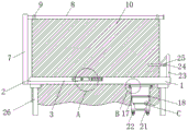
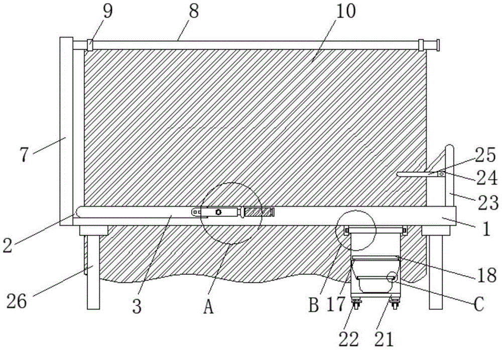
FIG. 1 is a schematic side view of the present invention;
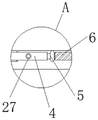
FIG. 2 is an enlarged schematic view of the structure at A of FIG. 1 according to the present invention;
FIG. 3 is an enlarged schematic view of the structure of FIG. 1 at B according to the present invention;
fig. 4 is an enlarged schematic structural diagram of the point C in fig. 1 according to the present invention.
In the figure: 1-a support bed body, 2-an upper body support plate placing groove, 3-an upper body support plate, 4-a pressing connecting rod, 5-a handle, 6-an anti-skidding sleeve, 7-a suspender support plate, 8-a roller shutter suspender, 9-a roller shutter sliding block, 10-a roller shutter, 11-a fixed connecting block, 12-a sliding chute, 13-a moving box connecting block, 14-a roller, 15-a roller connecting shaft, 16-a support device, 17-a cushion, 18-a sealing cover, 19-a collecting basin placing groove, 20-a dirt collecting basin, 21-a moving platform, 22-a pulley, 23-a protective guard, 24-a support plate connecting frame, 25-a support plate, 26-a support column and 27-a fastening bolt.
Detailed Description
The technical solutions in the embodiments of the present invention will be described clearly and completely with reference to the accompanying drawings in the embodiments of the present invention, and it is obvious that the described embodiments are only some embodiments of the present invention, not all embodiments.
Referring to fig. 1 to 4, the present invention provides a technical solution: a multifunctional obstetric nursing bed comprises a support bed body 1, the support bed body 1 can support a lying-in woman, an upper body support plate placing groove 2 is formed in one side of the support bed body 1, an upper body support plate 3 is arranged inside the upper body support plate placing groove 2, the upper body support plate 3 can support the upper body of the lying-in woman, pressing connecting rods 4 are movably connected to two sides of the support bed body 1, fastening bolts 27 are inserted into one sides of the pressing connecting rods 4, the pressing connecting rods 4 can be fixed by adjusting the fastening bolts 27, one ends of the fastening bolts 27 penetrate through the pressing connecting rods 4 and are in threaded connection with the support bed body 1, the upper body support plate 3 can be driven to incline by pressing the connecting rods 4 through a pressing handle 5, so that the upper limbs of the lying-in woman are lifted, one ends, far away from the support bed body 1, of the pressing connecting rods 4 are, one side of the supporting bed body 1 is fixedly connected with a suspender supporting plate 7, the suspender supporting plate 7 plays a supporting role for the roller shutter suspender 8, one side of the suspender supporting plate 7 far away from the supporting bed body 1 is fixedly connected with the roller shutter suspender 8, the outer surface of the roller shutter suspender 8 is sleeved with a roller shutter sliding block 9, the roller shutter sliding block 9 can be driven to slide on the roller shutter suspender 8 by pulling the roller shutter 10, so that the roller shutter 10 can be pulled open, one side of the roller shutter sliding block 9 is fixedly connected with the roller shutter 10, the roller shutter 10 can play a role of shielding a puerpera after being pulled open, one side of the bottom of the supporting bed body 1 is fixedly connected with a fixed connecting block 11, two sides inside the fixed connecting block 11 are both provided with a sliding groove 12, the roller 14 can slide in the sliding groove 12, a movable box connecting block 13 is arranged inside the fixed connecting block 11, a roller 14 is arranged inside the, one end of the roller connecting shaft 15, which is far away from the roller 14, is movably connected with the movable box connecting block 13, the bottom of the movable box connecting block 13 is fixedly connected with a movable supporting box, the front of the movable supporting box is fixedly connected with a supporting appliance 16, a lying-in woman can sit on the supporting appliance 16 to relieve the bowels, the top of the supporting appliance 16 is provided with a cushion 17, the comfort level of the lying-in woman can be improved by the cushion 17, the top, which is subjected to the cushion 17, is provided with a sealing cover 18, the sealing cover 18 plays a sealing role to prevent peculiar smell from being emitted indoors, one side of the sealing cover 18 is hinged with the movable supporting box, the bottom of the supporting appliance 16 is provided with a collecting basin placing groove 19, a dirt collecting basin 20 is arranged inside the collecting basin placing groove 19, the dirt can fall into the dirt collecting basin 20, the cleaning can be convenient for nursing personnel to clean, the outer surface of the handle 5 is sleeved with the anti-skidding sleeve 6, the bottom of the movable supporting box body is fixedly connected with a movable platform 21, the movable platform 21 can move through a pulley 22, the pulley 22 is arranged at the bottom of the movable platform 21, a protective guard 23 is fixedly connected to one side of the upper surface of the supporting bed body 1, a supporting plate connecting frame 24 is fixedly connected to one side of the protective guard 23, a supporting plate 25 is movably connected to the inside of the supporting plate connecting frame 24, and a supporting column 26 is fixedly connected to the bottom of the supporting bed body 1.
As an optimal technical solution of the utility model: the supporting device 16 is provided with a cavity inside, and the filth can fall into the filth collecting basin 20 through the cavity.
In conclusion, when the multifunctional obstetric nursing bed is used, through the arrangement of the fixed connecting block 11, the supporting device 16, the dirt collecting basin 20 and the sealing cover 18, when a puerpera needs to relieve the bowels, the supporting device 16 can be pulled out from the fixed connecting block 11, the puerpera can sit on the supporting device 16 to relieve the bowels, the dirt can fall into the dirt collecting basin 20 through the supporting device 16, great convenience is brought to the puerpera and nursing personnel, meanwhile, the sealing cover 18 can prevent peculiar smell from being emitted indoors to influence the indoor environment, when the dirt needs to be cleaned, only the dirt collecting basin 20 needs to be taken out and then cleaned, the working efficiency of medical personnel is greatly improved, through the arrangement of the handle 5, the pressing connecting rod 4, the upper body supporting plate 3 and the fastening bolt 27, after the fastening bolt 27 is screwed out, the nursing personnel can press the handle 5, handle 5 receives to press the back accessible and presses connecting rod 4 and drive upper portion body backup pad 3 and slope to can lift up the upper portion body of lying-in woman, the nursing staff of being convenient for supports the lying-in woman, makes it stand up, this process easy operation, labour saving and time saving has greatly improved nursing staff work efficiency, can change lying position of lying-in woman simultaneously, improves the comfort level of lying-in woman health.
In the description of the present invention, it is to be understood that the terms "center", "longitudinal", "lateral", "length", "width", "thickness", "upper", "lower", "front", "rear", "left", "right", "vertical", "horizontal", "top", "bottom", "inner", "outer", "clockwise", "counterclockwise", "axial", "radial", "circumferential", and the like, indicate the orientation or positional relationship indicated based on the drawings, and are only for convenience of description and simplicity of description, and do not indicate or imply that the device or element referred to must have a particular orientation, be constructed and operated in a particular orientation, and therefore, should not be construed as limiting the present invention.
In the present invention, unless otherwise expressly stated or limited, the terms "disposed," "mounted," "connected," "secured," and the like are to be construed broadly, e.g., as meaning fixedly connected, detachably connected, or integrally formed; they may be mechanically coupled, directly coupled, or indirectly coupled through intervening agents, both internally and/or in any other manner known to those skilled in the art. The specific meaning of the above terms in the present invention can be understood according to specific situations by those skilled in the art.
Furthermore, the terms "first", "second" and "first" are used for descriptive purposes only and are not to be construed as indicating or implying relative importance or implicitly indicating the number of technical features indicated. Thus, a feature defined as "first" or "second" may explicitly or implicitly include one or more of that feature. In the description of the present invention, "a plurality" means two or more unless specifically limited otherwise.
It is noted that in the present disclosure, unless otherwise explicitly specified or limited, a first feature "on" or "under" a second feature may be directly contacting the first and second features or indirectly contacting the first and second features through an intermediate. Also, a first feature "on," "over," and "above" a second feature may be directly or diagonally above the second feature, or may simply indicate that the first feature is at a higher level than the second feature. A first feature being "under," "below," and "beneath" a second feature may be directly under or obliquely under the first feature, or may simply mean that the first feature is at a lesser elevation than the second feature.
The above, only be the concrete implementation of the preferred embodiment of the present invention, but the protection scope of the present invention is not limited thereto, and any person skilled in the art is in the technical scope of the present invention, according to the technical solution of the present invention and the utility model, the concept of which is equivalent to replace or change, should be covered within the protection scope of the present invention.