CN210519196U - Ventilation cooling type flame proof switch board - Google Patents
Ventilation cooling type flame proof switch board Download PDFInfo
- Publication number
- CN210519196U CN210519196U CN201921621047.4U CN201921621047U CN210519196U CN 210519196 U CN210519196 U CN 210519196U CN 201921621047 U CN201921621047 U CN 201921621047U CN 210519196 U CN210519196 U CN 210519196U
- Authority
- CN
- China
- Prior art keywords
- control cabinet
- explosion
- proof
- top surface
- breathing sheet
- Prior art date
- Legal status (The legal status is an assumption and is not a legal conclusion. Google has not performed a legal analysis and makes no representation as to the accuracy of the status listed.)
- Active
Links
- 238000009423 ventilation Methods 0.000 title claims abstract description 16
- 238000001816 cooling Methods 0.000 title claims abstract description 9
- 230000029058 respiratory gaseous exchange Effects 0.000 claims abstract description 43
- 230000017525 heat dissipation Effects 0.000 claims abstract description 19
- 210000004907 gland Anatomy 0.000 claims abstract description 11
- 229910001220 stainless steel Inorganic materials 0.000 claims abstract description 6
- 239000010935 stainless steel Substances 0.000 claims abstract description 6
- 238000005245 sintering Methods 0.000 claims abstract description 5
- 238000004880 explosion Methods 0.000 claims description 14
- XAGFODPZIPBFFR-UHFFFAOYSA-N aluminium Chemical compound [Al] XAGFODPZIPBFFR-UHFFFAOYSA-N 0.000 claims description 7
- 229910052782 aluminium Inorganic materials 0.000 claims description 7
- 230000000241 respiratory effect Effects 0.000 claims 1
- 230000000694 effects Effects 0.000 abstract description 5
- 230000035699 permeability Effects 0.000 abstract description 3
- 238000009434 installation Methods 0.000 description 6
- 230000009286 beneficial effect Effects 0.000 description 1
- 238000003889 chemical engineering Methods 0.000 description 1
- 238000012824 chemical production Methods 0.000 description 1
- 239000003245 coal Substances 0.000 description 1
- 239000003814 drug Substances 0.000 description 1
- 239000002360 explosive Substances 0.000 description 1
- 238000010438 heat treatment Methods 0.000 description 1
- 238000004519 manufacturing process Methods 0.000 description 1
- 239000003208 petroleum Substances 0.000 description 1
- 238000007789 sealing Methods 0.000 description 1
- 239000004753 textile Substances 0.000 description 1
Images


Landscapes
- Cooling Or The Like Of Electrical Apparatus (AREA)
Abstract
The utility model discloses a ventilation heat dissipation type flame-proof control cabinet, which comprises a control cabinet, wherein the control cabinet is fixedly arranged on a mounting rack, the front side of the control cabinet is connected with a control cabinet door through a hinge, the left side surface, the rear side surface and the right side surface of the control cabinet are provided with radiating fins, and the outer top surface of the control cabinet is provided with a ceiling; the top surface of the control cabinet is provided with a vent hole, a rubber pad, an explosion-proof breathing sheet surrounding frame and a gland are arranged below the vent hole, the outer side of the explosion-proof breathing sheet surrounding frame is provided with a fan mounting rod, and the lower end of a fan mounting side is fixed with an axial flow fan; the utility model discloses can effectively realize the inside cooling of switch board, explosion-proof breathing piece on the switch board is formed by the sintering of multilayer stainless steel mesh, has certain gas permeability and very high mechanical strength, can have better explosion-proof effect when guaranteeing that the air can pass through like this.
Description
Technical Field
The utility model relates to a flame proof switch board field, concretely relates to ventilation cooling type flame proof switch board.
Background
With the development of national economy, the explosion-proof electrical products are widely applied to flammable and explosive places in the industries of petroleum, chemical engineering, war industry, coal, textile, medicine, food processing, marine transportation and the like, and the civilized production is an indispensable part in the modern chemical production. In the prior art, explosion-proof control cabinets are applied, because the cabinet body needs to meet explosion-proof requirements, the sealing is tight, the heat dissipation area of the cabinet body is small, and the mode of adding an air conditioner heat dissipation device or an aluminum plate heat dissipation device is generally adopted for heat dissipation of high-power elements in the cabinet at present; when the air conditioner is adopted for heat dissipation, the cost is high, the air conditioner is applied to the explosion-proof control cabinet with insufficient calorific value, the time-frequency modulation is frequently started to influence the service life, and the aluminum plate radiator is adopted, so that the heat dissipation effect is limited, and the aluminum plate radiator is not suitable for the control cabinet with large calorific value; until now, no satisfactory solution exists for the heat dissipation problem of the flameproof control cabinet.
SUMMERY OF THE UTILITY MODEL
The utility model provides a ventilation cooling type flame proof switch board can effectively realize the inside cooling of switch board, and explosion-proof breathing piece on the switch board is formed by the sintering of multilayer stainless steel mesh, has certain gas permeability and very high mechanical strength, can have better explosion-proof effect when guaranteeing that the air can pass through like this.
In order to solve the technical problem, the utility model provides a following solution:
a ventilation and heat dissipation type explosion-proof control cabinet comprises a control cabinet, wherein the control cabinet is fixedly installed on an installation frame, the front side of the control cabinet is connected with a control cabinet door through a hinge, heat dissipation fins for dissipating heat of the control cabinet are respectively and fixedly installed on the outer sides of the left side surface, the rear side surface and the right side surface of the control cabinet, a plurality of explosion-proof wiring pipes are fixedly installed on the outer bottom surface of the control cabinet, and a ceiling with a horizontal projection surface larger than that of the control cabinet is fixedly installed above the outer top surface of the control cabinet; a circular vent hole is arranged in the middle of the top surface of the control cabinet, a circular rubber pad with the inner diameter equal to the diameter of the vent hole is fixedly arranged at the concentric position below the vent hole on the inner top surface of the control cabinet, an explosion-proof breathing sheet with the diameter equal to the outer diameter of the rubber pad is tightly attached to the bottom surface of the rubber pad, the explosion-proof breathing sheet coincides with the vertical central line of the rubber pad, a circular explosion-proof breathing sheet surrounding frame with the inner diameter matched with the diameter of the explosion-proof breathing sheet is fixed at the edge of the vent hole on the inner top surface of the control cabinet, the inner side surface of the explosion-proof breathing sheet surrounding frame is tightly attached to the explosion-proof breathing sheet, the outer side surface of the rubber pad, the bottom surface of the explosion-proof breathing sheet surrounding frame is flush with the bottom surface, the vertical central lines of the vent holes are superposed, and the gland presses the anti-explosion breathing sheet and the rubber pad on the inner top surface of the control cabinet through bolts; an axial flow fan with the wind direction facing the outside of the control cabinet is fixed on the inner top surface of the control cabinet below the anti-explosion breathing sheet.
Furthermore, the explosion-proof breathing sheet is formed by sintering a plurality of layers of stainless steel nets.
Furthermore, the radiating fins are formed by transversely arranging a plurality of vertical aluminum strips.
Furthermore, the front projection of the ceiling is rectangular, and the left projection of the ceiling is conical.
Further, the axial flow fan is located right below the vent hole.
Further, the ceiling is fixedly installed on the outer top surface of the control cabinet through a ceiling installation frame.
Further, axial fan passes through fan installation stick fixed mounting on top surface in the switch board, and axial fan's wind direction is outside.
Further, the outer diameter of the gland is equal to that of the explosion-proof breathing sheet surrounding frame.
Compared with the prior art, the beneficial effects of the utility model are that:
1. the middle of the top surface of the control cabinet is provided with a vent hole, an anti-explosion breathing sheet is fixed below the vent hole, and an axial flow fan with outward wind direction is fixedly arranged below the anti-explosion breathing sheet, the axial flow fan can exchange hot air in the cabinet body to the outside or transmit the hot air to the surface of the cabinet body through the anti-explosion breathing hole, and then the heat is dissipated by matching with radiating fins arranged on the left side surface, the rear side surface and the right side surface of the control cabinet, so that the internal cooling of the control cabinet can be conveniently, simply and effectively realized;
2. the explosion-proof breathing sheet is formed by sintering a plurality of layers of stainless steel meshes, has certain air permeability and very high mechanical strength, and thus, the explosion-proof breathing sheet has better explosion-proof effect while ensuring that air can pass through;
3. the radiating fins are formed by transversely arranging a plurality of aluminum strips, so that heat on the control cabinet body can be quickly radiated;
4. the axial flow fan is arranged right below the vent hole, and the center line of the axial flow fan is superposed with the center line of the vent hole, so that the air inside and outside the control cabinet can be exchanged more quickly to achieve the purpose of radiating more quickly;
5. the ceiling that the horizontal projection face is greater than the switch board horizontal projection face is fixedly mounted to top of the outer top surface of the switch board, and the ceiling has the functions of shading sunlight and preventing rainwater from entering the switch board.
Drawings
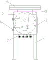
Fig. 1 is a front view of the present invention;
FIG. 2 is a left side view and partial cross-sectional view of FIG. 1;
fig. 3 is an enlarged view of a partial sectional view of fig. 2.
Description of the drawings: 1. mounting bracket, 2, fin, 3, ceiling mounting bracket, 4, ceiling, 5, control cabinet door, 6, hinge, 7, explosion-proof wiring pipe, 8, switch board, 9, axial fan, 10, rubber pad, 11, explosion-proof breathing piece, 12, ventilation hole, 13, explosion-proof breathing piece enclose frame, 14, fan installation stick, 15, gland, 16, bolt.
Detailed Description
As shown in fig. 1-3, a ventilation and heat dissipation type explosion-proof control cabinet comprises a control cabinet (8), wherein the control cabinet (8) is fixedly installed on an installation frame (1), the front side of the control cabinet (8) is connected with a control cabinet door (5) through a hinge (6), the outer sides of the left side surface, the rear side surface and the right side surface of the control cabinet (8) are respectively and fixedly provided with a radiating fin (2) for radiating the control cabinet (8), the radiating fin (2) is formed by transversely arranging a plurality of vertical aluminum strips, the outer bottom surface of the control cabinet (8) is fixedly provided with a plurality of explosion-proof wiring pipes (7), a ceiling (4) with a horizontal projection surface larger than that of the control cabinet is fixedly installed above the outer top surface of the control cabinet (8) through a ceiling installation frame (3), the front side projection of the ceiling (4) is rectangular, and the left side projection of; a circular vent hole (12) is formed in the middle of the top surface of the control cabinet (8), a circular rubber pad (10) with the inner diameter equal to the diameter of the vent hole (12) is fixedly arranged at the concentric position below the vent hole (12) on the inner top surface of the control cabinet (8), an explosion-proof breathing sheet (11) which is sintered by a plurality of layers of stainless steel nets and has the diameter equal to the outer diameter of the rubber pad (10) is tightly attached to the bottom surface of the rubber pad (10), the explosion-proof breathing sheet (11) is superposed with the vertical central line of the rubber pad (10), a circular explosion-proof breathing sheet surrounding frame (13) with the inner diameter matched with the diameter of the explosion-proof breathing sheet (11) is fixed at the edge of the vent hole (12) on the inner top surface of the control cabinet (8), the inner side surface of the explosion-proof breathing sheet surrounding frame (13) is tightly attached to the explosion-proof breathing sheet (11), the outer side surface of the rubber, an annular gland (15) with the inner diameter equal to the diameter of the vent hole (12) and the outer diameter equal to the outer diameter of the explosion-proof breathing sheet surrounding frame (13) is tightly attached to the bottom surface of the explosion-proof breathing sheet surrounding frame (13), the vertical central lines of the gland (15) and the vent hole (12) are overlapped, and the gland (15) tightly presses the explosion-proof breathing sheet (11) and the rubber pad (10) onto the inner top surface of the control cabinet (8) through a bolt (16); an axial flow fan (9) with the wind direction facing the outside of the control cabinet (8) is fixedly arranged on the inner top surface of the control cabinet (8) under the explosion-proof breathing sheet (11) through a fan mounting rod (14).
The working principle is as follows: when the external environment temperature of the control cabinet 8 is low or the heating value of components inside the control cabinet 8 is not large, the temperature of the control cabinet 8 body is low, a small amount of heat in the control cabinet 8 can exchange heat with the control cabinet 8 body through air to cool the control cabinet 8, and then the heat on the control cabinet 8 body is dissipated through the radiating fins 2 on the control cabinet 8; when 8 external environment temperature of switch board is higher or 8 internal components and parts calorific capacity is great, lean on the heat exchange in the switch board 8 alone to dispel the heat and have not reached wanted radiating effect, can open the axial fan 9 in the switch board 8 this moment, thereby derive switch board 8 with some heat through explosion-proof breathing fin 11 and accelerate the air flow in the switch board 8 and more rapidly spread the heat to switch board 8, then dispel the temperature through fin 2 on the switch board 8.
The axial flow fan 9 is a conventional one, and is not described herein again.
Claims (8)
1. A ventilation heat dissipation type flame-proof control cabinet is characterized in that: the anti-explosion control cabinet comprises a control cabinet (8), wherein the control cabinet (8) is fixedly arranged on a mounting frame (1), the front side of the control cabinet (8) is connected with a control cabinet door (5) through a hinge (6), the outer sides of the left side surface, the rear side surface and the right side surface of the control cabinet (8) are respectively and fixedly provided with a cooling fin (2) for cooling the control cabinet (8), the outer bottom surface of the control cabinet (8) is fixedly provided with a plurality of anti-explosion wiring pipes (7), and a ceiling (4) with a horizontal projection surface larger than that of the control cabinet is fixedly arranged above the outer top surface of the control cabinet (8); a circular vent hole (12) is formed in the middle of the top surface of the control cabinet (8), a circular rubber pad (10) with the inner diameter equal to the diameter of the vent hole (12) is fixedly arranged at a concentric position below the vent hole (12) on the inner top surface of the control cabinet (8), an anti-explosion breathing sheet (11) with the diameter equal to the outer diameter of the rubber pad (10) is tightly attached to the bottom surface of the rubber pad (10), the anti-explosion breathing sheet (11) is overlapped with the vertical central line of the rubber pad (10), a circular anti-explosion breathing sheet surrounding frame (13) with the inner diameter matched with the diameter of the anti-explosion breathing sheet (11) is fixed at the edge of the vent hole (12) on the inner top surface of the control cabinet (8), a circular gland (15) with the inner diameter equal to the diameter of the vent hole (12) is tightly attached to the inner side surface of the anti-explosion breathing sheet surrounding frame (13) and the outer side surface of the rubber pad (10), and the bottom surface of the anti-explosion breathing sheet surrounding frame (13), the vertical central lines of the gland (15) and the vent hole (12) are superposed, and the gland (15) presses the anti-explosion breathing sheet (11) and the rubber pad (10) on the inner top surface of the control cabinet (8) through a bolt (16); an axial flow fan (9) with the wind direction facing the outside of the control cabinet (8) is fixed on the inner top surface of the control cabinet (8) below the explosion-proof breathing sheet (11).
2. The ventilation and heat dissipation type flameproof control cabinet according to claim 1, characterized in that: the explosion-proof breathing sheet (11) is formed by sintering a plurality of layers of stainless steel nets.
3. The ventilation and heat dissipation type flameproof control cabinet according to claim 1, characterized in that: the radiating fins (2) are formed by transversely arranging a plurality of vertical aluminum strips.
4. The ventilation and heat dissipation type flameproof control cabinet according to claim 1, characterized in that: the front projection of the ceiling (4) is rectangular, and the left projection of the ceiling (4) is conical.
5. The ventilation and heat dissipation type flameproof control cabinet according to claim 1, characterized in that: the axial flow fan (9) is positioned right below the explosion-proof breathing sheet (11).
6. The ventilation and heat dissipation type flameproof control cabinet according to claim 1, characterized in that: the ceiling (4) is fixedly arranged on the outer top surface of the control cabinet (8) through a ceiling mounting frame (3).
7. The ventilation and heat dissipation type flameproof control cabinet according to claim 1, characterized in that: the axial flow fan (9) is fixedly arranged on the inner top surface of the control cabinet (8) through a fan mounting rod (14).
8. The ventilation and heat dissipation type flameproof control cabinet according to claim 1, characterized in that: the outer diameter of the gland (15) is equal to that of the explosion-proof respiratory slice surrounding frame (13).
Priority Applications (1)
| Application Number | Priority Date | Filing Date | Title |
|---|---|---|---|
| CN201921621047.4U CN210519196U (en) | 2019-09-27 | 2019-09-27 | Ventilation cooling type flame proof switch board |
Applications Claiming Priority (1)
| Application Number | Priority Date | Filing Date | Title |
|---|---|---|---|
| CN201921621047.4U CN210519196U (en) | 2019-09-27 | 2019-09-27 | Ventilation cooling type flame proof switch board |
Publications (1)
| Publication Number | Publication Date |
|---|---|
| CN210519196U true CN210519196U (en) | 2020-05-12 |
Family
ID=70571811
Family Applications (1)
| Application Number | Title | Priority Date | Filing Date |
|---|---|---|---|
| CN201921621047.4U Active CN210519196U (en) | 2019-09-27 | 2019-09-27 | Ventilation cooling type flame proof switch board |
Country Status (1)
| Country | Link |
|---|---|
| CN (1) | CN210519196U (en) |
-
2019
- 2019-09-27 CN CN201921621047.4U patent/CN210519196U/en active Active
Similar Documents
| Publication | Publication Date | Title |
|---|---|---|
| CN102523723A (en) | Radiating machine cabinet and electronic device | |
| CN210624740U (en) | Electrical box assembly, outdoor unit and air conditioner | |
| CN204616254U (en) | A kind of radiating cabinet | |
| CN103912361A (en) | Liquid cooling radiator of engine with electromagnetic shielding device | |
| CN206165085U (en) | Special good LED display screen box structure of thermal diffusivity | |
| CN205266107U (en) | Special rack of server that heat dispersion is good | |
| CN203009026U (en) | Engine liquid cooling radiator with electromagnetic shielding device | |
| CN211152591U (en) | High-efficient heat dissipation formula mining mechanical control case | |
| CN106972372A (en) | Transformer station | |
| CN206302348U (en) | A kind of radiating structure of frequency converter | |
| CN211739471U (en) | Fan device of roof machine and have its roof machine | |
| CN213818736U (en) | Explosion-proof braking resistance box | |
| CN204887855U (en) | Electronic vortex formula compressor control box that dispels heat | |
| CN211457421U (en) | Electronic ballast for ultraviolet lamp | |
| CN209118221U (en) | Intelligent terminal radiator structure | |
| CN218976093U (en) | Distribution box | |
| CN220798884U (en) | General electronic equipment control box | |
| CN206673406U (en) | The air-cooled heat dissipation structure of intelligent junction box | |
| CN219535384U (en) | Electrical installation cabinet | |
| CN110808544B (en) | Power distribution cabinet and power distribution system | |
| CN219698095U (en) | Waterproof construction of switch board | |
| CN214478652U (en) | Power equipment heat abstractor for communication engineering | |
| CN206312629U (en) | A kind of cable heat abstractor with temperature alarm function | |
| CN220307670U (en) | Heat radiation structure of frequency converter | |
| CN219389921U (en) | Electrical apparatus box, off-premises station and air conditioner |
Legal Events
| Date | Code | Title | Description |
|---|---|---|---|
| GR01 | Patent grant | ||
| GR01 | Patent grant |