CN210499690U - Efficient cup burnishing machine - Google Patents
Efficient cup burnishing machine Download PDFInfo
- Publication number
- CN210499690U CN210499690U CN201921543936.3U CN201921543936U CN210499690U CN 210499690 U CN210499690 U CN 210499690U CN 201921543936 U CN201921543936 U CN 201921543936U CN 210499690 U CN210499690 U CN 210499690U
- Authority
- CN
- China
- Prior art keywords
- cup body
- feeding
- cup
- clamping
- grinding
- Prior art date
- Legal status (The legal status is an assumption and is not a legal conclusion. Google has not performed a legal analysis and makes no representation as to the accuracy of the status listed.)
- Expired - Fee Related
Links
- 230000007246 mechanism Effects 0.000 claims abstract description 80
- 238000000227 grinding Methods 0.000 claims abstract description 54
- 239000000463 material Substances 0.000 claims abstract description 23
- 238000000034 method Methods 0.000 claims abstract description 16
- 230000008569 process Effects 0.000 claims abstract description 15
- 230000000712 assembly Effects 0.000 claims description 8
- 238000000429 assembly Methods 0.000 claims description 8
- 229920000742 Cotton Polymers 0.000 claims description 5
- 239000004744 fabric Substances 0.000 claims description 5
- 230000009471 action Effects 0.000 claims description 3
- 238000007599 discharging Methods 0.000 claims description 3
- 238000005498 polishing Methods 0.000 abstract description 20
- 238000010586 diagram Methods 0.000 description 5
- 238000007517 polishing process Methods 0.000 description 5
- 210000003781 tooth socket Anatomy 0.000 description 5
- 238000003754 machining Methods 0.000 description 2
- 238000004519 manufacturing process Methods 0.000 description 2
- 230000000694 effects Effects 0.000 description 1
- 230000010354 integration Effects 0.000 description 1
- 239000003973 paint Substances 0.000 description 1
- 238000004321 preservation Methods 0.000 description 1
- 238000003825 pressing Methods 0.000 description 1
- 238000004018 waxing Methods 0.000 description 1
Images





Landscapes
- Finish Polishing, Edge Sharpening, And Grinding By Specific Grinding Devices (AREA)
Abstract
The utility model discloses an efficient cup body polishing machine, which comprises a grinding assembly and a cup body feeding assembly, wherein the cup body feeding assembly comprises a clamping mechanism, a material ejecting mechanism, a feeding frame and a main shaft, the clamping mechanism and the material ejecting mechanism are arranged on the feeding frame and rotate along with the main shaft, the grinding assembly is arranged on the outer ring of the cup body feeding assembly, a feeding turntable and an ejecting cylinder are also arranged on the cup body feeding assembly, when the feeding frame is positioned at the position of the feeding turntable, the jacking cylinder controls the jacking mechanism to jack and lift the cup body, the feeding frame rotates to the grinding assembly along with the main shaft and stays for a period of time to polish the cup body, in the process, the clamping mechanism clamps the cup body, when the main shaft drives the feeding frame to continue rotating to the other feeding turntable, the jacking cylinder controls the jacking mechanism to enable the cup body to descend to the initial height, and in the process, the clamping mechanism loosens to release the fixation of the cup body. The utility model provides a prior art equipment step, the numerous and diverse problem of spare part, simplify the design to equipment, the cost is lower.
Description
Technical Field
The utility model belongs to the technical field of automation equipment technique and specifically relates to an efficient cup burnishing machine is related to.
Background
Polishers, also known as grinders, are often used for mechanical grinding, polishing, and waxing. The working principle is as follows: the motor drives the polishing disk arranged on the polishing machine to rotate at a high speed, and the polishing workpiece on the polishing disk rubs the surface to be polished, so that the aims of removing paint surface pollution, oxide layer and shallow mark can be fulfilled. In the heat preservation cup processing field, often can use abrasive band polishing machine to come to carry out the rough polishing process to the cup, abrasive band polishing mechanism structure among the prior art is complicated, and the circuit gas circuit is arranged complicatedly, need use the part of a plurality of different functions to accomplish different processes such as material loading, pay-off, cup fastening and rotation, polishing, unloading in actual work, complex operation often need shut down when entering into different processes moreover, and work efficiency is low.
Disclosure of Invention
The utility model provides a not enough to prior art, the utility model provides an efficient cup burnishing machine is integrating material loading, pay-off, cup fastening and the process of multichannel difference such as rotation, polishing, unloading on the basis of an equipment, has done the simplification to holistic spare part, and equipment is compacter, has reduced manufacturing cost simultaneously.
The utility model provides a technical scheme that its technical problem adopted is: an efficient cup body polishing machine comprises a grinding assembly and a cup body feeding assembly, wherein the cup body feeding assembly comprises a clamping mechanism, an ejection mechanism, a feeding frame and a main shaft, the clamping mechanism and the ejection mechanism are mounted on the feeding frame and rotate along with the main shaft, the grinding assembly is arranged on the outer ring of the cup body feeding assembly, a feeding turntable and an ejection cylinder are further arranged on the cup body feeding assembly, when the feeding frame is located at the position of the feeding turntable, the ejection cylinder controls the ejection mechanism to eject and lift a cup body, the feeding frame rotates along with the main shaft to the position of the grinding assembly and stays for a period of time to polish the cup body, in the process, the clamping mechanism clamps the cup body tightly, when the main shaft drives the feeding frame to continue to rotate to the position of the other feeding turntable, the ejection cylinder controls the ejection mechanism to enable the cup body to descend to the initial height, during this process, the clamping mechanism is released to release the cup from its hold. Accomplish the cup through an equipment and carry the pay-off carousel, the cup on the pay-off carousel presss from both sides tightly after the lifting of liftout mechanism, does not influence the cup when pressing from both sides tightly and rotates, exports from the second pay-off carousel after the twice polishing, can polish a plurality of cups simultaneously, and the whole operation is smooth, can the continuous operation, need not to shut down the operation.
In the above technical solution, preferably, the material ejecting mechanism includes an upper tooth post, a lower tooth post, and a limiting sleeve, the upper tooth post is connected to the feeding frame in a longitudinal rotation manner, a tray capable of moving longitudinally along the upper tooth post is disposed above the upper tooth post, a cup is disposed on the tray, the limiting sleeve is fixed on the feeding frame, a guide groove and a limiting tooth socket are disposed on the limiting sleeve, the upper tooth post and the lower tooth post are incompletely engaged and only have a tooth tip, the upper tooth post is provided with a guide tooth, the lower tooth post is provided with a guide strip, the guide tooth and the guide strip are simultaneously disposed in the guide groove to slide, a spring is disposed between the upper tooth post and the limiting sleeve, the lower tooth post pushes the upper tooth post upwards to leave the limit position of the guide groove so that the upper tooth post is engaged with the limiting tooth socket and slides and rotates along the inclined plane of the limiting tooth socket, at the moment, the guide teeth of the upper tooth column cannot fall into the guide groove, the cup body is jacked up to enable the clamping mechanism to be located in the cup body, when the upper tooth column is pushed upwards through the lower tooth column again, the guide teeth leave the limiting tooth grooves under the action of the springs and are meshed with the lower tooth column and slide and rotate until the guide teeth slide into the guide groove, and at the moment, the cup body descends and leaves the clamping mechanism.
In the above technical scheme, preferably, the feeding frame comprises a connecting seat, an ejection supporting seat and a clamping supporting seat, the ejection supporting seat is connected to the connecting seat, the clamping supporting seat is mounted above the clamping supporting seat, the clamping mechanism is rotatably connected with the clamping supporting seat, the ejection mechanism is mounted on the ejection supporting seat, and the upper tooth post is rotatably connected with the ejection supporting seat and can move longitudinally.
In the above technical scheme, preferably, the clamping mechanism is connected with the clamping support seat through a plurality of groups of bearings, the clamping mechanism includes a top shaft, a shaft sleeve and a plurality of clamping blocks, the clamping blocks are slidably connected to the shaft sleeve, an annular spring is arranged outside the clamping blocks to limit the clamping blocks to be separated from the shaft sleeve, the top shaft is inserted in the shaft sleeve, the bottom end portion of the top shaft is conical and is wedged with the clamping blocks, and the clamping blocks are pushed downwards through the top shaft to support the cup body outwards.
In the above technical scheme, preferably, the clamping mechanism is further provided with a gear, the gear is meshed with a motor gear of an external motor, and the motor drives the clamping mechanism to drive the cup body to rotate.
In the above technical scheme, preferably, the number of the feeding turnplate and the number of the jacking cylinders are two, wherein one of the feeding turnplate is responsible for feeding the cup body, and the other feeding turnplate is responsible for discharging the cup body.
In the above technical scheme, preferably, the cup body feeding assembly further includes a first main motor and a sheave mechanism, the first main motor drives the main shaft to intermittently move through the sheave mechanism, the main shaft drives the clamping mechanism on the feeding frame to stay for a period of time when being located at the feeding turntable or the grinding assembly, the feeding turntable is connected with the main shaft through a connecting shaft and a gear set, the main shaft drives the gear set to rotate, and the gear set drives the connecting shaft to drive the feeding turntable to intermittently move.
In the above technical solution, preferably, there are 2 grinding assemblies, a polishing device of the grinding assembly is a combination of a driven wheel, a driving wheel and an abrasive belt, the abrasive belt is installed on the driving wheel and the driven wheel, the driving wheel drives the abrasive belt to rotate, and the abrasive belt and the cup body rotate in opposite directions.
In the above technical scheme, preferably, there are 4 grinding assemblies, the grinding assembly is provided with a grinding turntable, wherein 2 grinding turntables of the grinding assemblies are provided with cotton wheels, the other 2 grinding turntables of the grinding assemblies are provided with cloth wheels, and the grinding turntables and the cup body rotate in opposite directions.
The utility model has the advantages that: the utility model discloses fasten material loading, pay-off, cup and rotate, the process integration of multichannel difference such as polishing, unloading in an equipment, improve the burnishing machine structure complicacy of prior art, under the condition that realizes the same effect, make the structure simplify greatly, manufacturing cost is lower. The whole polishing process is high in synchronism, low efficiency caused by step-by-step processing of the process in the traditional operation mode is solved, and continuous polishing of the cup body can be completed without stopping the machine.
Drawings
The present invention will be further explained with reference to the drawings and examples.
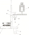
Fig. 1 is a schematic structural view of the cup body feeding assembly of the present invention.
Fig. 2 is another angle structure diagram of the cup body feeding assembly of the present invention.
Fig. 3 is a structural arrangement diagram of the first embodiment of the present invention.
Fig. 4 is a structural arrangement diagram of a second embodiment of the present invention.
Fig. 5 is a schematic structural view of the clamping mechanism of the present invention.
Fig. 6 is a schematic structural view of a clamping mechanism at another angle according to the present invention.
Fig. 7 is a schematic view of the internal structure of the clamping mechanism of the present invention.
Fig. 8 is an internal structural schematic diagram of the initial state of the clamping mechanism of the present invention.
Fig. 9 is an internal structure diagram of the upper tooth post in the jacked state according to the present invention.
Fig. 10 shows the state of the upper tooth post of the present invention disengaged from the guide groove and the limit tooth groove.
Fig. 11 is a schematic structural view of the upper tooth post and the lower tooth post of the present invention.
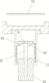
In the figure, 1, a grinding assembly, 2, a cup body feeding assembly, 3, a clamping mechanism, 4, a material ejecting mechanism, 5, a feeding frame, 6, a main shaft, 7, a feeding rotary table, 8, an ejecting cylinder, 9, an upper toothed column, 91, a guide tooth, 10, a lower toothed column, 101, a guide strip, 11, a limiting sleeve, 12, a tray, 13, a guide groove, 14, a limiting toothed groove, 15, a spring, 16, a connecting seat, 17, an ejecting supporting seat, 18, a clamping supporting seat, 19, an ejecting shaft, 20, a shaft sleeve, 21, a clamping block, 22, an annular spring, 23, a bearing, 24, a sheave mechanism, 25, a driven wheel, 26, a driving wheel, 27, an abrasive belt, 28, a grinding rotary table, 29, a cotton wheel, 30, a cloth wheel, 31, a connecting shaft, 32, a gear set and 33, a motor.
Detailed Description
In fig. 1-11, an efficient cup polishing machine comprises a grinding assembly 1 and a cup feeding assembly 2, wherein the cup feeding assembly 2 comprises a clamping mechanism 3, an ejection mechanism 4, a feeding frame 5 and a main shaft 6, the clamping mechanism 3 and the ejection mechanism 4 are mounted on the feeding frame 5 and rotate along with the main shaft 6, the grinding assembly 1 is arranged on an outer ring of the cup feeding assembly 2, the cup feeding assembly 2 is further provided with a feeding turntable 7 and an ejection cylinder 8, when the feeding frame 5 is located at the position of the feeding turntable 7, the ejection cylinder 8 controls the ejection mechanism 4 to eject and lift a cup, the feeding frame 5 rotates along with the main shaft 6 to the grinding assembly 1 to polish the cup for a period of time, in the process, the clamping mechanism 3 clamps the cup, and the main shaft 6 drives the feeding frame 5 to continue to rotate to the other feeding turntable 7, the jacking cylinder 8 controls the jacking mechanism 4 to enable the cup body to descend to the initial height, and in the process, the clamping mechanism 3 is loosened to release the fixation of the cup body.
The material ejecting mechanism 4 comprises an upper toothed column 9, a lower toothed column 10 and a limiting sleeve 11, the upper toothed column 9 is longitudinally rotatably connected with the feeding frame 5, a tray 12 capable of longitudinally moving along the upper toothed column 9 is arranged above the upper toothed column 9, a cup body is arranged on the tray 12, the limiting sleeve 11 is fixed on the feeding frame 5, a guide groove 13 and a limiting tooth groove 14 are arranged on the limiting sleeve 11, the upper toothed column 9 and the lower toothed column 10 are not completely meshed, a guide tooth 91 is arranged on the upper toothed column 9, a guide strip 101 is arranged on the lower toothed column 10, the guide tooth 91 and the guide strip 101 are simultaneously arranged in the guide groove 13 to slide, a spring 15 is arranged between the upper toothed column 9 and the limiting sleeve 11, and the lower toothed column 10 pushes the guide tooth 91 of the upper toothed column 9 upwards to leave the limiting position of the guide groove 13 so that the upper toothed column 9 is meshed with the limiting tooth groove 14, and the cup body slides and rotates along the inclined plane of the limit tooth socket 14, at this time, the guide teeth 91 of the upper tooth post 9 cannot fall into the guide groove 13, the cup body is jacked up to enable the clamping mechanism 3 to be positioned in the cup body, when the upper tooth post 9 is pushed upwards through the lower tooth post 10 again, the guide teeth 91 leave the limit tooth socket 14 under the action of the spring 15, are meshed with the lower tooth post 10 and slide and rotate until the guide teeth slide and fall into the guide groove 13, and at this time, the cup body descends to leave the clamping mechanism 3.
The feeding frame 5 comprises a connecting seat 16, an ejection supporting seat 17 and a clamping supporting seat 18, the ejection supporting seat 18 is connected to the connecting seat 16, the clamping supporting seat 18 is installed above the ejection supporting seat 17, and the clamping mechanism 3 is rotatably connected with the clamping supporting seat 18 through multiple groups of bearings 23. The material ejecting mechanism 4 is installed on the material ejecting support seat 17, and the upper tooth column 9 is rotatably connected with the material ejecting support seat 17 and can move longitudinally.
The clamping mechanism 3 is further provided with a gear, the gear is meshed with a motor gear of an external motor, and the motor drives the clamping mechanism 3 to drive the cup body to rotate. The cup body rotates reversely when the polishing wheel or the abrasive belt rotates at a high speed, and the working efficiency is improved.
The material feeding rotary table 7 and the jacking air cylinder 8 are provided with two material feeding rotary tables, wherein one material feeding rotary table 7 is used for feeding the cup body, and the other material feeding rotary table 7 is used for discharging the cup body.
The cup body feeding assembly 2 further comprises a first main motor (not shown in the figure, which is mounted below the driving dial of the geneva mechanism and drives the driving dial to rotate), a geneva mechanism 24, wherein the first main motor drives the main shaft 6 to intermittently move through the geneva mechanism 24, the main shaft 6 drives the clamping mechanism 3 on the feeding frame 5 to stay for a period of time when being positioned at the feeding turntable 7 or the grinding assembly 1, the feeding turntable 7 is connected with the main shaft 6 through a connecting shaft 31 and a gear set 32, the main shaft 6 drives the gear set 32 to rotate, and the gear set 32 drives the connecting shaft 31 to drive the feeding turntable 7 to intermittently move. The timing of the grinding is controlled by the timing of the interval of rotation of the drive shaft 6 by the Geneva gear 24.
Referring to fig. 3, a first embodiment of the present invention: the number of the grinding assemblies is 2, the grinding device of the grinding assembly 1 is a combination of a driven wheel 25, a driving wheel 26 and an abrasive belt 27, the abrasive belt 27 is installed on the driving wheel 26 and the driven wheel 25, the driving wheel 26 drives the abrasive belt 27 to rotate, and the rotational direction of the abrasive belt 27 is opposite to that of the cup body. This embodiment is used for the rough polishing process of cup, comes to carry out two rough polishing to the cup through abrasive band 27, and abrasive band 27 is opposite with the motion direction of cup, and two kinds of reverse speed difference have promoted machining efficiency.
Referring to fig. 4, a second embodiment of the present invention: the grinding assembly 1 is provided with 4 grinding rotary tables 28, wherein the grinding rotary tables 28 of 2 grinding assemblies are provided with cotton wheels 29, the grinding rotary tables 28 of the other 2 grinding assemblies 1 are provided with cloth wheels 30, and the rotating directions of the grinding rotary tables 28 and the cup body are opposite. This embodiment is used for the finish polishing process of cup, carries out the finish polishing to the cup part of cup through 2 cotton wheels 29 earlier, then enters into 2 cloth wheels and carries out the finish polishing to the oral area of cup, and grinding turntable 28 is opposite with the direction of motion of cup, and two kinds of reverse speed difference have also promoted machining efficiency.
The utility model discloses a working process: the cup body is conveyed to a feeding port on a first feeding turntable 71 from an external feeding track, the connecting shaft 31 is driven to rotate through the linkage of a lower spindle 6 and a gear set 32, so that the feeding turntable 71 is driven to convey the cup body to the position above a material ejecting mechanism 4 on a feeding frame 5, the material ejecting mechanism 4 is pushed and pressed through a jacking cylinder 8, the cup body is lifted by one end distance, the cup body can be tightly supported from the inside by a clamping mechanism 3, the feeding frame 5 is driven by the spindle 6 to move to a working area of a grinding assembly 1, the cup body is polished through the grinding assembly 1, the cup body is driven to rotate through an external motor in the grinding process, after 2-4 grinding and polishing processes, the spindle 6 drives the feeding frame 5 to drive the cup body to convey to a second feeding turntable 72, and the material ejecting mechanism 4 is pushed and pressed for the second time through the jacking cylinder 8, make the cup resume initial level, pay-off carousel 72 receives the rotation of connecting axle 31 to carry the cup from pay-off frame 5 the utility model discloses an on outside track or the region.
Claims (9)
1. The utility model provides an efficient cup burnishing machine which characterized in that: the cup body feeding assembly comprises a clamping mechanism, a material ejecting mechanism, a feeding frame and a main shaft, wherein the clamping mechanism and the material ejecting mechanism are mounted on the feeding frame and rotate along with the main shaft, the grinding assembly is arranged on the outer ring of the cup body feeding assembly, the cup body feeding assembly is further provided with a feeding turntable and a jacking cylinder, when the feeding frame is located at the position of the feeding turntable, the jacking cylinder controls the material ejecting mechanism to eject and lift the cup body, the feeding frame rotates along with the main shaft to the position of the grinding assembly and stays for a period of time to polish the cup body, in the process, the clamping mechanism clamps the cup body, the main shaft drives the feeding frame to continue to rotate to the position of the other feeding turntable, the jacking cylinder controls the material ejecting mechanism to enable the cup body to descend to the initial height, during this process, the clamping mechanism is released to release the cup from its hold.
2. The high efficiency cup polisher in accordance with claim 1 with the following features: the material ejecting mechanism comprises an upper toothed column, a lower toothed column and a limiting sleeve, the upper toothed column is longitudinally and rotatably connected with the feeding frame, a tray capable of moving along the upper toothed column is arranged above the upper toothed column, a cup body is arranged on the tray, the limiting sleeve is fixed on the feeding frame, a guide groove and a limiting tooth groove are arranged on the limiting sleeve, the upper toothed column and the lower toothed column are not completely meshed and only have tooth tips, guide teeth are arranged on the upper toothed column, a guide strip is arranged on the lower toothed column, the guide teeth and the guide strip are simultaneously arranged in the guide groove to slide, a spring is arranged between the upper toothed column and the limiting sleeve, the lower toothed column upwards pushes the upper toothed column to leave the limit position of the guide groove so that the upper toothed column is meshed with the limiting tooth groove and slides and rotates along the inclined plane of the limiting tooth groove, at the moment, the guide teeth of the upper toothed column cannot fall into the guide groove, the cup body is jacked up to enable the clamping mechanism to be located in the cup body, when the upper tooth post is pushed upwards through the lower tooth post again, the guide teeth leave the limiting tooth grooves under the action of the springs and are meshed with the lower tooth post and slide and rotate until the guide teeth slide into the guide grooves, and at the moment, the cup body descends to leave the clamping mechanism.
3. The high efficiency cup polisher in accordance with claim 2 with the following features: the feeding frame comprises a connecting seat, an ejection supporting seat and a clamping supporting seat, wherein the ejection supporting seat is connected to the connecting seat, the clamping supporting seat is installed above the clamping supporting seat, a clamping mechanism is rotatably connected with the clamping supporting seat, the ejection mechanism is installed on the ejection supporting seat, and the upper tooth column is rotatably connected with the ejection supporting seat and can move longitudinally.
4. A high efficiency cup polisher in accordance with claim 3 with the following features: the clamping mechanism is connected with the clamping support seat through a plurality of groups of bearings and comprises a top shaft, a shaft sleeve and a plurality of clamping blocks, the clamping blocks are connected on the shaft sleeve in a sliding mode, annular springs are arranged on the outer sides of the clamping blocks to limit the clamping blocks to be separated from the shaft sleeve, the top shaft is inserted into the shaft sleeve, the bottom end portion of the top shaft is conical and is wedged with the clamping blocks, and the clamping blocks are pushed downwards through the top shaft to be outwards tightly supported on the cup body.
5. The efficient cup polisher in accordance with claim 4, further comprising: the clamping mechanism is further provided with a gear, the gear is meshed with a motor gear of an external motor, and the motor drives the clamping mechanism to drive the cup body to rotate.
6. The high efficiency cup polisher in accordance with claim 1 with the following features: the feeding rotary disc and the jacking cylinder are provided with two parts, wherein one part is responsible for feeding the cup body, and the other part is responsible for discharging the cup body.
7. The high efficiency cup polisher in accordance with claim 1 with the following features: the cup feeding assembly further comprises a first main motor and a sheave mechanism, the first main motor drives the main shaft to move intermittently through the sheave mechanism, the main shaft drives a clamping mechanism on the feeding frame to stay for a period of time at the position of the feeding turntable or the grinding assembly, the feeding turntable is connected with the main shaft through a connecting shaft and a gear set, the main shaft drives the gear set to rotate, and the gear set drives the connecting shaft to drive the feeding turntable to move intermittently.
8. The high efficiency cup polisher in accordance with any one of claims 1-7 with the following features: the grinding assembly is provided with 2 grinding assemblies, a grinding device of each grinding assembly is a combination of a driven wheel, a driving wheel and an abrasive belt, the abrasive belts are arranged on the driving wheel and the driven wheel, the driving wheel drives the abrasive belts to rotate, and the rotating directions of the abrasive belts and the cup body are opposite.
9. The high efficiency cup polisher in accordance with any one of claims 1-7 with the following features: the grinding assembly is provided with 4 grinding rotary tables, wherein 2 grinding rotary tables of the grinding assembly are provided with cotton wheels, the other 2 grinding rotary tables of the grinding assembly are provided with cloth wheels, and the rotation directions of the grinding rotary tables and the cup body are opposite.
Priority Applications (1)
| Application Number | Priority Date | Filing Date | Title |
|---|---|---|---|
| CN201921543936.3U CN210499690U (en) | 2019-09-17 | 2019-09-17 | Efficient cup burnishing machine |
Applications Claiming Priority (1)
| Application Number | Priority Date | Filing Date | Title |
|---|---|---|---|
| CN201921543936.3U CN210499690U (en) | 2019-09-17 | 2019-09-17 | Efficient cup burnishing machine |
Publications (1)
| Publication Number | Publication Date |
|---|---|
| CN210499690U true CN210499690U (en) | 2020-05-12 |
Family
ID=70570359
Family Applications (1)
| Application Number | Title | Priority Date | Filing Date |
|---|---|---|---|
| CN201921543936.3U Expired - Fee Related CN210499690U (en) | 2019-09-17 | 2019-09-17 | Efficient cup burnishing machine |
Country Status (1)
| Country | Link |
|---|---|
| CN (1) | CN210499690U (en) |
Cited By (1)
| Publication number | Priority date | Publication date | Assignee | Title |
|---|---|---|---|---|
| CN110480485A (en) * | 2019-09-17 | 2019-11-22 | 永康市凌城达机械设备制造有限公司 | An Efficient Cup Body Polishing Machine |
-
2019
- 2019-09-17 CN CN201921543936.3U patent/CN210499690U/en not_active Expired - Fee Related
Cited By (2)
| Publication number | Priority date | Publication date | Assignee | Title |
|---|---|---|---|---|
| CN110480485A (en) * | 2019-09-17 | 2019-11-22 | 永康市凌城达机械设备制造有限公司 | An Efficient Cup Body Polishing Machine |
| CN110480485B (en) * | 2019-09-17 | 2024-06-07 | 南京谦之源信息科技有限公司 | Efficient cup polishing machine |
Similar Documents
| Publication | Publication Date | Title |
|---|---|---|
| CN110480485B (en) | Efficient cup polishing machine | |
| CN105150065B (en) | A kind of new buffing machine of multi-station disc type | |
| CN110394718B (en) | A high-efficiency cup body abrasive belt polishing device | |
| CN201769102U (en) | Rotary disc multi-station automatic polishing machine | |
| CN111113219A (en) | A mobile phone case turntable CNC sanding machine | |
| CN111283525A (en) | Full-automatic polishing machine | |
| CN221735793U (en) | A continuous multi-station polishing machine | |
| CN106078470B (en) | Bearing polishing detection integrated device | |
| CN109202563A (en) | A kind of efficient grinding apparatus of bearing machining | |
| CN210335508U (en) | Fine polishing machine for vacuum cup | |
| CN211277845U (en) | Cell-phone shell revolving stage numerical control grinder | |
| CN215239952U (en) | Multistation burnishing and polishing all-in-one | |
| CN115070585A (en) | Magnetic ring cleaning and grinding device | |
| CN118357848B (en) | Polishing equipment for machining brake disc of vehicle brake | |
| CN210476440U (en) | Automatic polishing device for bearing manufacturing | |
| CN210550438U (en) | Cup body ejection clamping mechanism on polishing machine | |
| CN220128352U (en) | Edging device for screw production | |
| CN210335461U (en) | Efficient cup abrasive band burnishing device | |
| CN219725739U (en) | Industrial polishing machine for acrylic plates | |
| CN210281882U (en) | Turntable driving mechanism of polishing machine | |
| CN218856591U (en) | Multi-station efficient CMP polishing machine | |
| CN118254102A (en) | Double-sided grinding and polishing equipment with upper plate adjustment mechanism and use method thereof | |
| CN113400164B (en) | Automatic polishing equipment inside casting container | |
| CN210704170U (en) | A high-precision polishing machine | |
| CN210281871U (en) | Clamp for grinding cup mouth |
Legal Events
| Date | Code | Title | Description |
|---|---|---|---|
| GR01 | Patent grant | ||
| GR01 | Patent grant | ||
| CF01 | Termination of patent right due to non-payment of annual fee | ||
| CF01 | Termination of patent right due to non-payment of annual fee |
Granted publication date: 20200512 Termination date: 20210917 |