CN210479854U - Double-layer pressure conveyer - Google Patents
Double-layer pressure conveyer Download PDFInfo
- Publication number
- CN210479854U CN210479854U CN201921192731.5U CN201921192731U CN210479854U CN 210479854 U CN210479854 U CN 210479854U CN 201921192731 U CN201921192731 U CN 201921192731U CN 210479854 U CN210479854 U CN 210479854U
- Authority
- CN
- China
- Prior art keywords
- top layer
- frame
- conveying
- conveyor
- double
- Prior art date
- Legal status (The legal status is an assumption and is not a legal conclusion. Google has not performed a legal analysis and makes no representation as to the accuracy of the status listed.)
- Expired - Fee Related
Links
- 239000003638 chemical reducing agent Substances 0.000 claims description 17
- 230000005540 biological transmission Effects 0.000 claims description 3
- 239000000463 material Substances 0.000 abstract description 23
- 239000010410 layer Substances 0.000 description 66
- 230000001105 regulatory effect Effects 0.000 description 3
- 230000009286 beneficial effect Effects 0.000 description 1
- 239000002356 single layer Substances 0.000 description 1
Images

Landscapes
- Structure Of Belt Conveyors (AREA)
Abstract
The utility model provides a double-layer pressure conveyor, which comprises a frame, wherein a bottom conveying frame is fixedly arranged at the top of the frame, a first driving conveying roller and a first driven conveying roller are respectively arranged at two ends of the bottom conveying frame, a bottom conveying belt is arranged on the first driving conveying roller and the first driven conveying roller, and a main shaft where the first driving conveying roller is arranged and a bottom power device for driving the first driving conveying roller to rotate are arranged; the top layer conveying rack is installed on the bottom layer conveying rack through a parallelogram supporting structure, an inclined supporting rod used for adjusting the distance is installed between the parallelogram supporting structure and the bottom layer conveying rack, and a top layer conveying device is installed on the top layer conveying rack. This conveyer can be used for the material to carry, in the transportation process, can provide certain pressure to the material moreover, and then has guaranteed to carry out the pressure feed to the material, satisfies the requirement of carrying.
Description
Technical Field
The utility model relates to a conveyor field especially relates to a double-deck pressure conveyer.
Background
For some materials needing to exert certain pressure in the conveying process, a matched pressure conveyor is needed, the existing belt conveyor adopts a single-layer conveying structure, and the pressure cannot be exerted on the materials in the conveying process, so that the traditional conveyor needs to be improved.
SUMMERY OF THE UTILITY MODEL
For solving above technical problem, the utility model provides a double-deck pressure conveyer, this conveyer can be used for the material to carry, in the transportation process, can provide certain pressure to the material moreover, and then has guaranteed to carry out pressure conveying to the material, satisfies the requirement of carrying.
In order to realize the technical characteristics, the purpose of the utility model is realized as follows: the double-layer pressure conveyor comprises a rack, wherein a bottom layer conveying rack is fixedly mounted at the top of the rack, a first driving conveying roller and a first driven conveying roller are respectively mounted at two ends of the bottom layer conveying rack, a bottom layer conveying belt is mounted on the first driving conveying roller and the first driven conveying roller, and a main shaft of the first driving conveying roller and a bottom layer power device for driving the first driving conveying roller to rotate are mounted on the main shaft; the top layer conveying rack is installed on the bottom layer conveying rack through a parallelogram supporting structure, an inclined supporting rod used for adjusting the distance is installed between the parallelogram supporting structure and the bottom layer conveying rack, and a top layer conveying device is installed on the top layer conveying rack.
The foundation support plate is installed at the bottom four corners of the frame, and foundation bolts connected with the foundation are fixedly installed on the foundation support plate.
The bottom layer power device comprises a first motor, an output shaft of the first motor is connected with a first speed reducer, the output shaft of the first speed reducer is connected with a main shaft where a first driving conveying roller is located, and the first speed reducer is fixedly installed on the side wall of the bottom layer conveying rack.
And a feeding guide roller is arranged at the position of a feeding hole of the bottom layer conveying rack.
Parallelogram bearing structure includes first even board, first even board bottom articulates on the bottom lateral wall of frame is carried to the bottom through first bearing, first even board other end articulates the end at first supporting shaft, first supporting shaft supports and installs on the second bearing at top layer conveyor frame top, the top of frame is carried to the top layer is fixed with symmetrical arrangement's third bearing, install the second back shaft between the third bearing, it has the second even board to articulate on the second back shaft, the bottom of second even board articulates on the bottom lateral wall of frame is carried to the bottom through fourth bearing.
The top layer conveying device comprises a top layer conveying belt fixed on a top layer conveying rack, the top layer conveying belt is supported and installed between top layer conveying rollers, the top layer conveying rollers are driven to rotate through a top layer power device, the top layer power device comprises a second motor, an output shaft of the second motor is connected with a second speed reducer, and an output shaft of the second speed reducer is connected with one of the top layer conveying rollers and drives the top layer conveying roller to rotate.
Install the straining device who is used for carrying out the tensioning to conveyer belt separately on bottom conveyor frame and the top layer conveyor frame, straining device includes the tensioning screw rod, the screw thread transmission cooperation that passes through of tensioning screw rod is installed on the screw rod otic placode, screw rod otic placode fixed mounting is on the lateral wall of conveyor frame, the other end and the roller supporting seat of tensioning screw rod link to each other, the roller supporting seat passes through sliding fit and installs on the slide rail.
And the bottom end of the second connecting plate is provided with a limiting transverse plate, the limiting transverse plate is matched with a cushion pad fixed on a limiting transverse beam, and the limiting transverse beam is fixed at the bottom of the bottom layer conveying rack through a transverse beam support.
And side baffles are supported and installed on two sides of the top of the bottom layer conveying rack through side supporting plates.
The utility model discloses there is following beneficial effect:
1. the pressure conveyer through adopting above-mentioned structure can be used for the transport that needs exert pressure's material in transportation process, place the material on the bottom conveyer belt, carry the material through the foretell bottom conveyer belt of bottom power device drive, simultaneously through adjusting the bearing diagonal pole, and then adjust the interval between bottom conveyer belt and the top layer conveyor frame, reach the purpose of regulated pressure size, carry out pressure feed to the material that lies in between the two through top layer conveyor simultaneously, and then satisfy the transport requirement.
2. Can drive first reduction gear through first motor, by the first initiative conveying roller of first reduction gear drive again, and then through first initiative conveying roller drive bottom conveyer belt, realize the transport of material.
Drawings
The present invention will be further explained with reference to the drawings and examples.
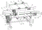
Fig. 1 is a first perspective three-dimensional view of the present invention.
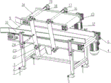
Fig. 2 is a second perspective three-dimensional view of the present invention.
Fig. 3 is a third perspective three-dimensional view of the present invention.
In the figure: the device comprises foundation bolts 1, foundation support plates 2, a frame 3, a first motor 4, a bottom layer conveying frame 5, a first speed reducer 6, a first driving conveying roller 7, a feeding guide roller 8, a bottom layer conveying belt 9, a side baffle plate 10, a side support plate 11, a second motor 12, a second speed reducer 13, a top layer conveying belt 14, a top layer conveying frame 15, a first support shaft 16, a second bearing seat 17, a second support shaft 18, a third bearing seat 19, a first bearing seat 20, a first connecting plate 21, a fourth bearing seat 22, a second connecting plate 23, an inclined support rod 24, a screw lug plate 25, a tensioning screw 26, a roller shaft support seat 27, a slide rail 28, a first driven conveying roller 29, a top layer conveying roller 30, a limiting transverse plate 31, a cushion pad 32, a limiting transverse beam 33 and a transverse beam support seat 34.
Detailed Description
The following describes embodiments of the present invention with reference to the accompanying drawings.
Referring to fig. 1-3, the double-layer pressure conveyor includes a frame 3, a bottom layer conveyor frame 5 is fixedly mounted on the top of the frame 3, a first driving conveyor roller 7 and a first driven conveyor roller 29 are respectively mounted at two ends of the bottom layer conveyor frame 5, a bottom layer conveyor belt 9 is mounted on the first driving conveyor roller 7 and the first driven conveyor roller 29, and a main shaft of the first driving conveyor roller 7 is connected with a bottom layer power device for driving the first driving conveyor roller 7 to rotate; the top layer conveyor frame 15 is installed through parallelogram bearing structure on the bottom conveyor frame 5, install the bracing piece 24 that is used for the spacing of regulation between parallelogram bearing structure and the bottom conveyor frame 5, install top layer conveyor on the top layer conveyor frame 15. The pressure conveyer through adopting above-mentioned structure can be used for the transport that needs apply the material of pressure in transportation process, place the material on bottom conveyer belt 9, carry the material through foretell bottom conveyer belt 9 of bottom power device drive, simultaneously through adjusting bearing diagonal pole 24, and then adjust the interval between bottom conveyer belt 9 and the top layer conveyor frame 15, reach the purpose of regulated pressure size, carry out pressure feed to the material that lies in between the two through top layer conveyor simultaneously.
Furthermore, lower margin backup pad 2 is installed at the bottom four corners of frame 3, fixed mounting has the rag bolt 1 that is used for linking to each other with the ground on the lower margin backup pad 2. It has been guaranteed through rag bolt 1 that it can fix the whole conveyer.
Further, the bottom layer power device comprises a first motor 4, an output shaft of the first motor 4 is connected with a first speed reducer 6, an output shaft of the first speed reducer 6 is connected with a main shaft where a first driving conveying roller 7 is located, and the first speed reducer 6 is fixedly installed on the side wall of the bottom layer conveying rack 5. Can drive first reduction gear 6 through first motor 4, by first initiative conveying roller 7 of first reduction gear 6 drive again, and then through first initiative conveying roller 7 drive bottom conveyer belt 9, realize the transport of material.
Further, a feeding guide roller 8 is installed at the position of a feeding hole of the bottom layer conveyor frame 5. The purpose of feed guiding is served by the feed guiding roller 8.
Further, parallelogram bearing structure includes first even board 21, first even board 21's bottom articulates on the bottom lateral wall of bottom conveyor frame 5 through first bearing frame 20, first even board 21's the other end articulates the end at first supporting shaft 16, first supporting shaft 16 supports to be installed on the second bearing frame 17 at top layer conveyor frame 15 top, top layer conveyor frame 15's top is fixed with symmetrical arrangement's third bearing frame 19, install second back shaft 18 between the third bearing frame 19, it has even board 23 of second to articulate on the second back shaft 18, the bottom of even board 23 of second articulates on the bottom lateral wall of bottom conveyor frame 5 through fourth bearing frame 22. The normal rotation of the top layer conveyor frame 15 can be ensured through the parallelogram support structure, and then the conveying of materials with different heights is used.
Further, the top layer conveying device comprises a top layer conveying belt 14 fixed on a top layer conveying rack 15, the top layer conveying belt 14 is supported and installed between top layer conveying rollers 30, the top layer conveying rollers 30 are driven to rotate through a top layer power device, the top layer power device comprises a second motor 12, an output shaft of the second motor 12 is connected with a second speed reducer 13, and an output shaft of the second speed reducer 13 is connected with one of the top layer conveying rollers 30 and drives the same to rotate. By means of which the top conveyor belt 14 can be driven.
Further, install on bottom conveyor frame 5 and the top layer conveyor frame 15 and be used for carrying out the straining device of tensioning to conveyer belt separately, straining device includes tensioning screw 26, tensioning screw 26 installs on screw ear 25 through screw thread transmission cooperation, screw ear 25 fixed mounting is on the lateral wall of conveyor frame, tensioning screw 26's the other end links to each other with roller supporting seat 27, roller supporting seat 27 passes through sliding fit and installs on slide rail 28. The conveying belt can be tensioned through the tensioning mechanism with the structure.
Furthermore, a limiting transverse plate 31 is installed at the bottom end of the second connecting plate 23, the limiting transverse plate 31 is matched with a cushion pad 32 fixed on a limiting transverse beam 33, and the limiting transverse beam 33 is fixed at the bottom of the bottom layer conveying rack 5 through a transverse beam support 34. The cushion pad 32 can serve a cushioning purpose to prevent collision during adjustment.
Further, side baffles 10 are supported and installed on two sides of the top of the bottom layer conveying rack 5 through side supporting plates 11. The side baffle 10 can serve the purpose of stopping materials.
The utility model discloses a use as follows:
firstly, place the material that will carry on the bottom conveyer belt 9, carry the material through the foretell bottom conveyer belt 9 of bottom power device drive, simultaneously through adjusting bearing diagonal pole 24, and then adjust the interval between bottom conveyer belt 9 and the top layer conveyor frame 15, reach the purpose of regulated pressure size, carry out pressure feed to the material that lies in between the two through top layer conveyor simultaneously.
Claims (9)
1. Double-deck pressure conveyer, its characterized in that: the device comprises a rack (3), wherein a bottom layer conveying rack (5) is fixedly installed at the top of the rack (3), a first driving conveying roller (7) and a first driven conveying roller (29) are respectively installed at two ends of the bottom layer conveying rack (5), a bottom layer conveying belt (9) is installed on the first driving conveying roller (7) and the first driven conveying roller (29), and a main shaft where the first driving conveying roller (7) is located and a bottom layer power device for driving the first driving conveying roller (7) to rotate are installed; the top layer conveyor frame (15) is installed through parallelogram bearing structure on the bottom conveyor frame (5), install bracing strut (24) that are used for the spacing of regulation between parallelogram bearing structure and bottom conveyor frame (5), install top layer conveyor on top layer conveyor frame (15).
2. The double-deck pressure conveyor of claim 1, wherein: lower margin backup pad (2) are installed in the bottom four corners of frame (3), fixed mounting has rag bolt (1) that are used for linking to each other with the ground on lower margin backup pad (2).
3. The double-deck pressure conveyor of claim 1, wherein: the bottom layer power device comprises a first motor (4), an output shaft of the first motor (4) is connected with a first speed reducer (6), an output shaft of the first speed reducer (6) is connected with a main shaft where a first driving conveying roller (7) is located, and the first speed reducer (6) is fixedly installed on the side wall of the bottom layer conveying rack (5).
4. The double-deck pressure conveyor of claim 1, wherein: and a feeding guide roller (8) is arranged at the position of a feeding hole of the bottom layer conveying rack (5).
5. The double-deck pressure conveyor of claim 1, wherein: parallelogram bearing structure includes first even board (21), the bottom of first even board (21) articulates on the bottom lateral wall of bottom transport frame (5) through first bearing frame (20), the end at first supporting axle (16) is articulated to the other end of first even board (21), first supporting axle (16) support mounting is on second bearing frame (17) at top layer transport frame (15) top, the top of top layer transport frame (15) is fixed with third bearing frame (19) of symmetrical arrangement, install second back shaft (18) between third bearing frame (19), it has second even board (23) to articulate on second back shaft (18), the bottom of second even board (23) articulates on the bottom lateral wall of bottom transport frame (5) through fourth bearing frame (22).
6. The double-deck pressure conveyor of claim 1, wherein: the top layer conveying device comprises top layer conveying belts (14) fixed on a top layer conveying rack (15), the top layer conveying belts (14) are supported and installed between top layer conveying rollers (30), the top layer conveying rollers (30) are driven to rotate through a top layer power device, the top layer power device comprises a second motor (12), an output shaft of the second motor (12) is connected with a second speed reducer (13), and an output shaft of the second speed reducer (13) is connected with one of the top layer conveying rollers (30) and drives the top layer conveying rollers to rotate.
7. The double-deck pressure conveyor of claim 1, wherein: install on bottom conveyor frame (5) and top layer conveyor frame (15) and be used for carrying out the straining to conveyer belt separately, straining device includes tensioning screw rod (26), install on screw rod otic placode (25) through the screw thread transmission cooperation of tensioning screw rod (26), screw rod otic placode (25) fixed mounting is on the lateral wall of conveyor frame, the other end and the roller supporting seat (27) of tensioning screw rod (26) link to each other, roller supporting seat (27) are installed on slide rail (28) through sliding fit.
8. The double-deck pressure conveyor of claim 5, wherein: and a limiting transverse plate (31) is installed at the bottom end of the second connecting plate (23), the limiting transverse plate (31) is matched with a cushion pad (32) fixed on a limiting transverse beam (33), and the limiting transverse beam (33) is fixed at the bottom of the bottom layer conveying rack (5) through a transverse beam support (34).
9. The double-deck pressure conveyor of claim 5, wherein: and side baffles (10) are supported and installed on two sides of the top of the bottom layer conveying rack (5) through side supporting plates (11).
Priority Applications (1)
| Application Number | Priority Date | Filing Date | Title |
|---|---|---|---|
| CN201921192731.5U CN210479854U (en) | 2019-07-26 | 2019-07-26 | Double-layer pressure conveyer |
Applications Claiming Priority (1)
| Application Number | Priority Date | Filing Date | Title |
|---|---|---|---|
| CN201921192731.5U CN210479854U (en) | 2019-07-26 | 2019-07-26 | Double-layer pressure conveyer |
Publications (1)
| Publication Number | Publication Date |
|---|---|
| CN210479854U true CN210479854U (en) | 2020-05-08 |
Family
ID=70532924
Family Applications (1)
| Application Number | Title | Priority Date | Filing Date |
|---|---|---|---|
| CN201921192731.5U Expired - Fee Related CN210479854U (en) | 2019-07-26 | 2019-07-26 | Double-layer pressure conveyer |
Country Status (1)
| Country | Link |
|---|---|
| CN (1) | CN210479854U (en) |
Cited By (2)
| Publication number | Priority date | Publication date | Assignee | Title |
|---|---|---|---|---|
| CN113666119A (en) * | 2021-08-05 | 2021-11-19 | 巢湖市伟业玻璃有限公司 | Laminated glass bubble removing device and method |
| CN113665216A (en) * | 2021-08-05 | 2021-11-19 | 巢湖市伟业玻璃有限公司 | Laminated glass bubble removing device |
-
2019
- 2019-07-26 CN CN201921192731.5U patent/CN210479854U/en not_active Expired - Fee Related
Cited By (2)
| Publication number | Priority date | Publication date | Assignee | Title |
|---|---|---|---|---|
| CN113666119A (en) * | 2021-08-05 | 2021-11-19 | 巢湖市伟业玻璃有限公司 | Laminated glass bubble removing device and method |
| CN113665216A (en) * | 2021-08-05 | 2021-11-19 | 巢湖市伟业玻璃有限公司 | Laminated glass bubble removing device |
Similar Documents
| Publication | Publication Date | Title |
|---|---|---|
| CN207861344U (en) | A kind of novel jacking transferring machine | |
| CN206156248U (en) | Track conveyor that syllogic is adjustable | |
| CN108423377A (en) | A kind of narrowband formula transfer conveyer | |
| CN117068679A (en) | Steel pipe lifting machine | |
| CN106742274A (en) | A kind of multifunctional packaging manages stockline | |
| CN211495666U (en) | Commodity circulation letter sorting conveyer belt overspeed device tensioner | |
| CN211494690U (en) | Adjustable servo box feeding frame for vertical box packing machine | |
| CN222714381U (en) | Bandage loading attachment | |
| CN220411733U (en) | Chain conveying device for conveying straws | |
| CN213468520U (en) | Anti-blocking material distributing mechanism of roller screen | |
| CN201385800Y (en) | Conveyor capable of automatically stacking stuff | |
| CN112429517A (en) | Automatic magnet feeding equipment | |
| CN113635598B (en) | Feeding system of corrugated carton cutting machine | |
| CN214778468U (en) | Roller conveyor | |
| CN211003080U (en) | Automatic conveying device | |
| CN212502537U (en) | Bamboo chip feeding device | |
| CN214651244U (en) | Ball feeding device of ball bladder glue brushing machine | |
| CN211811800U (en) | Bidirectional driving conveying device | |
| CN212952465U (en) | A roller conveyor with easy height adjustment | |
| CN216887406U (en) | Pinch roller conveying equipment | |
| CN210311216U (en) | Bag arranging device for stacker crane | |
| CN222922259U (en) | Bundle steel conveyor | |
| CN223199654U (en) | A blanking mechanism for a cardboard slotting machine | |
| CN220843289U (en) | Flattening guide structure for tissue packaging machine | |
| CN220264098U (en) | Tensioning device of belt conveyor |
Legal Events
| Date | Code | Title | Description |
|---|---|---|---|
| GR01 | Patent grant | ||
| GR01 | Patent grant | ||
| CF01 | Termination of patent right due to non-payment of annual fee |
Granted publication date: 20200508 Termination date: 20210726 |
|
| CF01 | Termination of patent right due to non-payment of annual fee |