CN210464165U - Reinforced radiating pipe - Google Patents
Reinforced radiating pipe Download PDFInfo
- Publication number
- CN210464165U CN210464165U CN201921151989.0U CN201921151989U CN210464165U CN 210464165 U CN210464165 U CN 210464165U CN 201921151989 U CN201921151989 U CN 201921151989U CN 210464165 U CN210464165 U CN 210464165U
- Authority
- CN
- China
- Prior art keywords
- holes
- hole
- circular
- width direction
- rectangular
- Prior art date
- Legal status (The legal status is an assumption and is not a legal conclusion. Google has not performed a legal analysis and makes no representation as to the accuracy of the status listed.)
- Active
Links
- 238000001816 cooling Methods 0.000 claims abstract description 24
- 230000000694 effects Effects 0.000 abstract description 3
- 230000003014 reinforcing effect Effects 0.000 description 3
- 230000017525 heat dissipation Effects 0.000 description 2
- 238000000034 method Methods 0.000 description 2
- 238000007792 addition Methods 0.000 description 1
- 230000001174 ascending effect Effects 0.000 description 1
- 238000001125 extrusion Methods 0.000 description 1
- 238000012986 modification Methods 0.000 description 1
- 230000004048 modification Effects 0.000 description 1
- 238000006467 substitution reaction Methods 0.000 description 1
- 230000007704 transition Effects 0.000 description 1
Images


Landscapes
- Heat-Exchange Devices With Radiators And Conduit Assemblies (AREA)
Abstract
The utility model relates to a reinforced radiating tube, which comprises a tube body with a flat tubular structure, wherein a plurality of through holes along the length direction are arranged in the tube body, the through holes are arranged side by side along the width of the tube body, at least one of the through holes at the two ends in the width direction of the tube body is a circular hole, a rectangular hole is arranged between the circular holes at the two ends, the thicknesses of the tube walls at the two sides of the rectangular hole and the thicknesses between the rectangular holes are T, the thickness of the side wall of the circular hole, the distance between the circular hole and the rectangular hole and the distance between the adjacent circular holes are T1; the utility model provides a rectangular hole can increase the effective volume of cooling tube, realizes better radiating effect, and the circular port that both ends set up has strengthened the intensity of cooling tube width direction tip to the holistic intensity of cooling tube has been strengthened.
Description
Technical Field
The utility model relates to a radiator technical field specifically indicates a strenghthened type cooling tube.
Background
With the development of science and technology, particularly the rapid development of the automobile industry, the produced automobiles are higher and higher, the power is gradually improved, the internal pressure of a system is higher and higher, and the requirements on the heat dissipation capacity and the pressure bearing capacity of a radiator and a intercooler are higher and higher; wherein the cooling tube is the important spare part of radiator and intercooler, plays the key role to the heat-sinking capability and the structural strength of product, and the structural strength and the heat-sinking capability of current cooling tube can not keep up with the demand of automobile development far away at present.
Disclosure of Invention
The utility model discloses to prior art's not enough, provide a structural strength is good, strenghthened type cooling tube that the radiating efficiency is high.
The utility model discloses a following technical scheme realizes, provides a strenghthened type cooling tube, including the body of flat tubular structure, be provided with a plurality of through-holes along length direction in the body, the through-hole sets up side by side along body width direction, and the through-hole at both ends has at least one to be the circular port on the body width direction.
In this scheme the through-hole sets up side by side along body width direction, and the through-hole at both ends has at least one to be the circular port on the body width direction, because the intensity of round hole is higher, consequently can strengthen the intensity at body width direction's both ends to strengthen the intensity of whole cooling tube.
Preferably, the through holes between the circular holes are rectangular holes. Through-hole between the circular hole is the rectangular hole in this scheme, because body width direction middle part is lower to the requirement of intensity, consequently adopts the rectangular hole can increase the inside volume of cooling tube, reinforcing radiating efficiency.
Preferably, the thicknesses of the pipe walls on two sides of the rectangular hole and the thicknesses between the rectangular holes are both T, the thicknesses of the side walls of the circular holes, the distances between the circular holes and the rectangular holes and the distances between the adjacent circular holes are all T1, and T1 is larger than T. T1 is greater than T in this scheme to further strengthened between circular port lateral wall, circular port and the rectangular hole, the thickness between the adjacent circular port, thereby the structural strength at reinforcing cooling tube width direction both ends.
Preferably, T1 is 1.8 to 2.5 times of T. T1 is 1.8~2.5 times of T in this scheme, can be thickness around the increase circular port to when the intensity at reinforcing here, make the circular port keep at certain size, guarantee its heat dissipation function.
Preferably, two through holes at two ends of the tube body in the width direction are circular holes respectively. The through-hole at both ends respectively has two to be the circular port in the body width direction in this scheme, can further strengthen the intensity at cooling tube width direction both ends.
Preferably, four corners of the rectangular hole are rounded. The four corners in rectangular hole sets up to the fillet in this scheme, is convenient for process rectangular hole and can strengthen the intensity in rectangular hole.
Preferably, the length of the side of the rectangular hole adjacent to the circular hole in the width direction of the pipe body is smaller than the length of the rectangular hole in the height direction, and the remaining rectangular holes are square. The length of the rectangular hole adjacent to the circular hole in this scheme along body width direction is less than the length of height direction, and remaining rectangular hole is square, and consequently the rectangular hole adjacent to the circular hole is less than the length of quad slit along body width direction's length, and rectangular hole lateral wall intensity will be greater than the intensity of quad slit lateral wall to accomplish the transition of intensity between circular hole to the quad slit.
Preferably, both ends of the tube in the width direction are semicircular and concentric with the circular holes at the ends. The both ends of body width direction are semi-circular and concentric with the circular port of tip in this scheme, can make body width direction's both ends stress even, and save material cost.
The utility model has the advantages that: the utility model discloses be provided with a plurality of through-holes along length direction in the body, the through-hole at both ends has at least one to be the circular port on the body width direction, and the through-hole between the circular port at both ends sets up to the rectangular hole, and the rectangular hole can increase the effective volume of cooling tube, realizes better radiating effect, and the circular port that both ends set up has strengthened the intensity at cooling tube width direction both ends to the holistic intensity of cooling tube has been strengthened.
Drawings
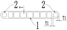
Fig. 1 is a schematic cross-sectional view of embodiment 1 of the present invention;
fig. 2 is a schematic structural view of embodiment 1 of the present invention;
fig. 3 is a schematic cross-sectional view of embodiment 2 of the present invention;
shown in the figure:
1. rectangular hole, 2, circular hole.
Detailed Description
In order to clearly illustrate the technical features of the present solution, the present solution is explained below by way of specific embodiments.
Example 1:
as shown in fig. 1 and 2, the utility model discloses a strenghthened type cooling tube, including the body of flat tubular structure, be provided with a plurality of through-holes along length direction in the body, the through-hole sets up side by side along the body width, and the ascending both ends of body width direction respectively have two through-holes to be circular port 2, and 2 sizes of all circular ports are the same, and the both ends of body width direction are semi-circular and concentric with the circular port 2 of tip.
Through-hole between the circular port 2 at both ends sets up to rectangular hole 1, and the four corners of rectangular hole 1 sets up to the fillet, and the highly the same and diameter that is greater than the circular port of all rectangular holes, the width of the adjacent rectangular hole of circular port is less than the height, and the width and the height of remaining rectangular hole are the same.
The thickness of the pipe walls on the upper side and the lower side of the rectangular hole 1 and the thickness between the rectangular holes 1 are both T, the thickness of the side wall of the circular hole 2 and the distance between the circular hole 2 and the rectangular hole 1 are both T1, and the T1 is 1.8-2.5 times of the T.
Example 2:
as shown in fig. 3, the present embodiment 2 is different from embodiment 1 in that: two through-holes are respectively two on the body width direction and are circular port 2, and two 2 shape dimensions of circular port are the same, and the interval between two adjacent circular port 2 is the same with the thickness that is 2 lateral walls of circular port, is T1.
The utility model discloses a use method: the utility model discloses a strenghthened type cooling tube is the porous structure cooling tube, forms through extrusion, and the body is flat tubular structure, stretches into the air chamber to the intercooler respectively with the cooling tube both ends to intercommunication inlet chamber and air outlet chamber, the high temperature air flow after the pressure boost flows through the cooling tube, and carries out the heat exchange with the external world through the pipe wall of cooling tube, thereby reduces air temperature.
The body embeds there is a plurality of through-holes along length direction, the through-hole sets up and both ends respectively are provided with at least one circular port 2 along the body width side by side, sets up to rectangular hole 1 between the circular port, and great air input can be realized to rectangular hole 1, realizes better radiating effect, and the circular port 2 that both ends set up has strengthened the intensity at cooling tube width direction both ends to the holistic intensity of cooling tube has been strengthened.
Of course, the above description is not limited to the above examples, and technical features of the present invention that are not described in the present application may be implemented by or using the prior art, and are not described herein again; the above embodiments and drawings are only used for illustrating the technical solutions of the present invention and are not intended to limit the present invention, and the present invention has been described in detail with reference to the preferred embodiments, and those skilled in the art should understand that changes, modifications, additions or substitutions made by those skilled in the art within the spirit of the present invention should also belong to the protection scope of the claims of the present invention.
Claims (8)
1. The utility model provides a strenghthened type cooling tube, includes the body of flat tubular structure, is provided with a plurality of through-holes along length direction in the body, its characterized in that: the through-holes are arranged side by side along the width direction of the pipe body, and at least one of the through-holes at the two ends of the pipe body in the width direction is a circular hole (2).
2. The reinforced heat pipe of claim 1 wherein: the through holes between the circular holes (2) are rectangular holes (1).
3. The reinforced heat pipe of claim 2 wherein: the thickness of the pipe wall of the two sides of each rectangular hole (1) and the thickness between the rectangular holes (1) are T, the thickness of the side wall of each circular hole (2), the distance between each circular hole (2) and each rectangular hole (1) and the distance between each adjacent circular holes (2) are T1, and T1 is larger than T.
4. The reinforced heat pipe of claim 3 wherein: the T1 is 1.8-2.5 times of T.
5. The reinforced heat pipe of claim 1 wherein: the through-hole at both ends respectively has two to be circular port (2) on the body width direction.
6. The reinforced heat pipe of claim 2 wherein: four corners of the rectangular hole (1) are set to be round corners.
7. The reinforced heat pipe of claim 6 wherein: the length of a side of the rectangular hole adjacent to the circular hole in the width direction of the pipe body is smaller than that in the height direction, and the rest rectangular holes are square.
8. The reinforced heat pipe of claim 1 wherein: both ends of the pipe body in the width direction are semicircular and are concentric with the circular hole in the end part.
Priority Applications (1)
| Application Number | Priority Date | Filing Date | Title |
|---|---|---|---|
| CN201921151989.0U CN210464165U (en) | 2019-07-22 | 2019-07-22 | Reinforced radiating pipe |
Applications Claiming Priority (1)
| Application Number | Priority Date | Filing Date | Title |
|---|---|---|---|
| CN201921151989.0U CN210464165U (en) | 2019-07-22 | 2019-07-22 | Reinforced radiating pipe |
Publications (1)
| Publication Number | Publication Date |
|---|---|
| CN210464165U true CN210464165U (en) | 2020-05-05 |
Family
ID=70446803
Family Applications (1)
| Application Number | Title | Priority Date | Filing Date |
|---|---|---|---|
| CN201921151989.0U Active CN210464165U (en) | 2019-07-22 | 2019-07-22 | Reinforced radiating pipe |
Country Status (1)
| Country | Link |
|---|---|
| CN (1) | CN210464165U (en) |
-
2019
- 2019-07-22 CN CN201921151989.0U patent/CN210464165U/en active Active
Similar Documents
| Publication | Publication Date | Title |
|---|---|---|
| CN202101595U (en) | Longitudinal flow shell-and-tube heat exchanger | |
| CN102116591A (en) | Double-face fin plate tube structure for air cooler | |
| CN201364052Y (en) | Shell-and-tube heat exchanger | |
| CN1948885A (en) | Double-pipe metal foam heat exchanger | |
| CN102679787B (en) | Chain type heat exchange pipe | |
| CN201748836U (en) | Harmonica tube for heat radiation | |
| CN101995175A (en) | Shell-and-tube heat exchanger | |
| CN202692806U (en) | Tube-shell type heat exchanger | |
| CN206739954U (en) | A kind of high efficient heat exchanging internally finned tube | |
| CN204665982U (en) | A kind of water-cooled shell oil cooler | |
| CN211854968U (en) | Heat radiator | |
| CN216815159U (en) | Small-diameter finned heat exchanger | |
| CN203116579U (en) | Micro-channel high-efficiency aluminum flat pipe for air conditioner | |
| CN202866976U (en) | Flaring type cooling pipe and automobile radiator | |
| CN205332884U (en) | Novel finned heat exchanger | |
| CN212619486U (en) | High-performance low-cost condenser | |
| CN203013450U (en) | Large-caliber plate radiator | |
| CN212378583U (en) | Longitudinal inner and outer micro-rib heat exchange tube for heat exchanger | |
| CN202768123U (en) | Carrier for catalytic purifiers for motor vehicle exhaust | |
| CN202734637U (en) | Finned heat exchange tube | |
| CN207515049U (en) | A kind of steel bimetallic sliding radiator | |
| CN2467999Y (en) | Tubing | |
| CN204966225U (en) | Modularization aluminum alloy transformer radiator | |
| CN2750275Y (en) | Hole enlarged baffle plate heat exchanger | |
| CN209763794U (en) | Radiating pipe |
Legal Events
| Date | Code | Title | Description |
|---|---|---|---|
| GR01 | Patent grant | ||
| GR01 | Patent grant |