CN210462351U - Measuring device for civil engineering - Google Patents
Measuring device for civil engineering Download PDFInfo
- Publication number
- CN210462351U CN210462351U CN201921472918.0U CN201921472918U CN210462351U CN 210462351 U CN210462351 U CN 210462351U CN 201921472918 U CN201921472918 U CN 201921472918U CN 210462351 U CN210462351 U CN 210462351U
- Authority
- CN
- China
- Prior art keywords
- base
- fixed box
- rod
- threaded rod
- civil engineering
- Prior art date
- Legal status (The legal status is an assumption and is not a legal conclusion. Google has not performed a legal analysis and makes no representation as to the accuracy of the status listed.)
- Expired - Fee Related
Links
- 230000007423 decrease Effects 0.000 abstract 1
- 238000005259 measurement Methods 0.000 description 4
- 238000010276 construction Methods 0.000 description 3
- 239000004568 cement Substances 0.000 description 2
- 238000006243 chemical reaction Methods 0.000 description 2
- 230000004075 alteration Effects 0.000 description 1
- 230000009286 beneficial effect Effects 0.000 description 1
- 230000000694 effects Effects 0.000 description 1
- 238000005516 engineering process Methods 0.000 description 1
- 239000000463 material Substances 0.000 description 1
- 238000000034 method Methods 0.000 description 1
- 238000012986 modification Methods 0.000 description 1
- 230000004048 modification Effects 0.000 description 1
- 238000005381 potential energy Methods 0.000 description 1
- 239000002689 soil Substances 0.000 description 1
- 238000006467 substitution reaction Methods 0.000 description 1
Images



Landscapes
- Investigation Of Foundation Soil And Reinforcement Of Foundation Soil By Compacting Or Drainage (AREA)
Abstract
The utility model discloses a measuring device for civil engineering, including spirit level main part and fixed box, the base is installed to the downside of spirit level main part, and pegs graft and have the check lock lever in the inboard of base, the slider is installed to the base lateral surface, and the outside of slider is connected with the slide rail, fixed box sets up in the tail end of check lock lever, and the inside downside of fixed box installs the kelly, the upper right side of fixed box is provided with the rotor plate, and the left and right sides of fixed box all installs the threaded rod, the lower part outside of threaded rod is connected with the bracing piece. The device is provided with the check lock lever, through with in the check lock lever injects the base for the base rigidity, the check lock lever in the separate base utilizes the slider can be along the gliding characteristic of slide rail, and the base can be along the slide rail decline entering fixed box in, is provided with the thorn head, and the screw thread between thorn head and the bracing piece coincide, and the thorn head can be followed the bracing piece and dismantled down, convenient use place according to the difference is nimble to be changed.
Description
Technical Field
The utility model relates to a measuring device technical field specifically is a measuring device for civil engineering.
Background
Civil engineering is a general term of science and technology for building various land engineering facilities, which refers to applied materials, equipment, technical activities such as surveying, designing, constructing, maintaining and repairing, and the like, and also refers to objects of engineering construction, wherein measurement refers to describing observed phenomena by data according to a certain rule, namely, quantitative description is made on objects, and measurement refers to a quantitative process of non-quantitative real objects.
The existing measuring device is frequently required to use a level gauge in civil engineering measurement, when the measuring device is carried, the level gauge is directly exposed outside and is easy to damage, and the footing of the measuring device is inconvenient to convert under two different working environments of soil and cement on the ground.
Disclosure of Invention
An object of the utility model is to provide a measuring device for civil engineering to solve the measuring device who proposes in the above-mentioned background art, often need use the surveyor's level in the civil engineering survey, when carrying, the surveyor's level is direct to be exposed in the external world, harms easily, and under the operational environment that ground is two kinds of differences of earth and cement, the footing of device is not convenient for the problem of conversion.
In order to achieve the above object, the utility model provides a following technical scheme: the utility model provides a measuring device for civil engineering, includes spirit level main part and fixed box, the base is installed to the downside of spirit level main part, and pegs graft in the inboard of base and have the check lock lever, the slider is installed to the base lateral surface, and the outside of slider is connected with the slide rail, fixed box sets up in the tail end of check lock lever, and the inside downside of fixed box installs the kelly, the upper right side of fixed box is provided with the rotor plate, and the threaded rod is all installed to the left and right sides of fixed box, the lower part outside of threaded rod is connected with the bracing piece.
Preferably, the fixed box forms a clamping structure through the locking rod and the base, and the base forms a sliding structure through the sliding block and the sliding rail.
Preferably, the tail end of the clamping rod is sleeved with a spring, and the clamping rod forms an elastic structure with the fixed box through the spring.
Preferably, the outer side of the threaded rod is connected with a locking bolt, and the threaded rod forms a clamping structure with the fixed box through the locking bolt.
Preferably, the support rod is connected with the threaded rod in a meshing manner, and the support rod forms a telescopic structure with the fixed box through the threaded rod.
Preferably, the bottom end of the supporting rod is provided with a thorn head, and a detachable structure is formed between the thorn head and the supporting rod.
Compared with the prior art, the beneficial effects of the utility model are that:
1. the device is provided with a locking rod, the locking rod is inserted into the base to fix the position of the base, the locking rod in the base is separated, and the base can descend along the slide rail to enter the fixed box by utilizing the characteristic that the slide block can slide along the slide rail;
2. the clamping rod is arranged, the leveling instrument main body on the base is fixed in the fixing box by inserting the clamping rod into the base, and the base can leave the fixing box by pulling out the clamping rod, so that the leveling instrument main body is conveniently moved out of the fixing box;
3. the rotatable threaded rod is arranged, the threaded rod can rotate along the fixing box, so that the threaded rod is convenient to fold, and the threaded rod is fixed by screwing the locking bolt to abut against the threaded rod; the supporting rod is matched with the threads of the threaded rod, and the total length of the supporting rod and the threaded rod is changed by rotating the supporting rod, so that the height of the level main body is conveniently changed; the bayonet is arranged, threads between the bayonet and the supporting rod are matched, the bayonet can be detached from the supporting rod, and the use field can be flexibly changed according to different convenience.
Drawings
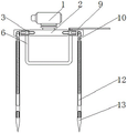
FIG. 1 is a schematic view of the main structure of the present invention;
FIG. 2 is a schematic view of the connection structure of the slide block and the slide rail of the present invention;
FIG. 3 is a schematic view of the connection structure between the clamping rod and the base of the present invention;
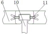
FIG. 4 is a schematic view of the connection structure between the threaded rod and the fixing box of the present invention;
fig. 5 is a schematic view of the connection structure of the support rod and the puncture head of the present invention.
In the figure: 1. a level body; 2. a base; 3. a locking lever; 4. a slider; 5. a slide rail; 6. a fixing box; 7. a clamping rod; 8. a spring; 9. a rotating plate; 10. a threaded rod; 11. locking the bolt; 12. a support bar; 13. pricking heads.
Detailed Description
The technical solutions in the embodiments of the present invention will be described clearly and completely with reference to the accompanying drawings in the embodiments of the present invention, and it is obvious that the described embodiments are only some embodiments of the present invention, not all embodiments. Based on the embodiments in the present invention, all other embodiments obtained by a person skilled in the art without creative work belong to the protection scope of the present invention.
Referring to fig. 1-5, the present invention provides a technical solution: a measuring device for civil engineering comprises a level main body 1 and a fixing box 6, a base 2 is arranged at the lower side of the level main body 1, and the inner side of the base 2 is inserted with a locking rod 3, the outer side of the base 2 is provided with a slide block 4, the outer side of the slide block 4 is connected with a slide rail 5, a fixed box 6 forms a clamping structure with the base 2 through the locking rod 3, and the base 2 forms a sliding structure through the sliding block 4 and the sliding rail 5, the locking rod 3 has a telescopic function, the telescopic end of the locking rod 3 is matched with the opening of the base 2, the locking rod 3 is inserted into the base 2 in an extending way, the base 2 is fixed, the device is provided with a locking rod 3, the position of the base 2 is fixed by inserting the locking rod 3 into the base 2, the locking rod 3 in the base 2 is separated, and the base 2 can descend along the slide rail 5 into a fixed box 6 by utilizing the characteristic that the slide block 4 can slide along the slide rail 5; fixed box 6 sets up in the tail end of check lock lever 3, and the inside downside of fixed box 6 installs kelly 7, and the tail end of kelly 7 has cup jointed spring 8, and kelly 7 passes through and constitutes elastic construction between spring 8 and the fixed box 6. The spring 8 has elasticity, the clamping rod 7 extrudes the spring 8 outwards to increase the elastic potential energy of the spring 8, the clamping rod 7 generates the force for restoring the original state, the clamping rod 7 is matched with the hole of the base 2, the clamping rod 7 is inserted into the base 2, the base 2 is fixed and provided with the clamping rod 7, the leveling instrument main body 1 on the base 2 is fixed in the fixing box 6 by inserting the clamping rod 7 into the base 2, the base 2 can leave the fixing box 6 by pulling out the clamping rod 7, and the leveling instrument main body 1 is convenient to move out of the fixing box 6;
the right upper side of the fixed box 6 is provided with a rotating plate 9, threaded rods 10 are mounted on the left side and the right side of the fixed box 6, a support rod 12 is connected to the outer side of the lower portion of each threaded rod 10, a locking bolt 11 is connected to the outer side of each threaded rod 10, each threaded rod 10 forms a clamping structure with the fixed box 6 through the locking bolt 11, the top of each threaded rod 10 is clamped in a groove of the fixed box 6, each threaded rod 10 can rotate along the fixed box 6, the locking bolt 11 is screwed to abut against the corresponding threaded rod 10, the threaded rods 10 are fixed, the threaded rods 10 can rotate and can be conveniently folded, and the threaded rods 10 are fixed by screwing the locking bolts 11 to abut against the threaded rods 10;
the support rod 12 is connected with the threaded rod 10 in an engagement mode, the support rod 12 forms a telescopic structure with the fixing box 6 through the threaded rod 10, the support rod 12 is engaged with the threads of the threaded rod 10, the support rod 12 is rotated to change the total length of the support rod 12 and the threaded rod 10, the support rod 12 is arranged, the support rod 12 is matched with the threads of the threaded rod 10, and the total length of the support rod 12 and the threaded rod 10 is changed by rotating the support rod 12, so that the height of the level main body 1 is convenient to change; thorn head 13 is installed to the bottom of bracing piece 12, and constitutes detachable construction between thorn head 13 and the bracing piece 12, through threaded connection between thorn head 13 and the bracing piece 12, thorn head 13 can be dismantled from bracing piece 12, is provided with thorn head 13, and the screw thread between thorn head 13 and the bracing piece 12 coincide, and thorn head 13 can be dismantled from bracing piece 12 down, and the convenience is according to the nimble conversion in use place of difference.
The working principle is as follows: for the measuring device, firstly, a fixing box 6 is carried to a place needing to be used, a locking bolt 11 is unscrewed, whether a puncture head 13 is used or not is determined according to a measuring field, the puncture head 13 is used when the ground of the field is soft, the puncture head 13 is aligned to a supporting rod 12, the puncture head 13 is installed at the bottom end of the supporting rod 12, the supporting rod 12 is rotated, the lengths of the supporting rod 12 and a threaded rod 10 are increased, after the threaded rod 10 is extended to a proper length, the threaded rod 10 is rotated to the bottom side of the fixing box 6, the locking bolt 11 is screwed down, the threaded rod 10 is fixed, a rotating plate 9 is pulled, the fixing box 6 is opened, a clamping rod 7 is pulled, a spring 8 is extruded, the clamping rod 7 is separated from a base 2, the base 2 is pulled upwards, a sliding block 4 is driven to slide along a sliding rail 5, the base 2 is pulled to the top of the fixing box 6, a locking rod 3 is extended, let check lock lever 3 inject 2 trompil departments of base, fix base 2, fix spirit level main part 1 at the upside of fixed box 6, the user measures the operation through spirit level main part 1, after the measurement, shrink check lock lever 3, withdraw spirit level main part 1 to fixed box 6 in, close rotor plate 9, accomplish whole measuring device's use like this.
Although embodiments of the present invention have been shown and described, it will be appreciated by those skilled in the art that changes, modifications, substitutions and alterations can be made in these embodiments without departing from the principles and spirit of the invention, the scope of which is defined in the appended claims and their equivalents.
Claims (6)
1. The utility model provides a measuring device for civil engineering, includes spirit level main part (1) and fixed box (6), its characterized in that: base (2) are installed to the downside of spirit level main part (1), and the inboard of base (2) is pegged graft and is had check lock lever (3), slider (4) are installed to base (2) lateral surface, and the outside of slider (4) is connected with slide rail (5), fixed box (6) set up in the tail end of check lock lever (3), and the inside downside of fixed box (6) installs kelly (7), the upper right side of fixed box (6) is provided with rotor plate (9), and threaded rod (10) are all installed to the left and right sides of fixed box (6), the lower part outside of threaded rod (10) is connected with bracing piece (12).
2. A measuring apparatus for civil engineering work according to claim 1, characterized in that: the fixed box (6) forms a clamping structure with the base (2) through the locking rod (3), and the base (2) forms a sliding structure with the sliding rail (5) through the sliding block (4).
3. A measuring apparatus for civil engineering work according to claim 1, characterized in that: the tail end of the clamping rod (7) is sleeved with a spring (8), and the clamping rod (7) forms an elastic structure with the fixed box (6) through the spring (8).
4. A measuring apparatus for civil engineering work according to claim 1, characterized in that: the outer side of the threaded rod (10) is connected with a locking bolt (11), and the threaded rod (10) forms a clamping structure with the fixing box (6) through the locking bolt (11).
5. A measuring apparatus for civil engineering work according to claim 1, characterized in that: the support rod (12) is connected with the threaded rod (10) in a meshing manner, and the support rod (12) forms a telescopic structure with the fixed box (6) through the threaded rod (10).
6. A measuring apparatus for civil engineering work according to claim 1, characterized in that: the bottom end of the supporting rod (12) is provided with a thorn head (13), and a detachable structure is formed between the thorn head (13) and the supporting rod (12).
Priority Applications (1)
| Application Number | Priority Date | Filing Date | Title |
|---|---|---|---|
| CN201921472918.0U CN210462351U (en) | 2019-09-05 | 2019-09-05 | Measuring device for civil engineering |
Applications Claiming Priority (1)
| Application Number | Priority Date | Filing Date | Title |
|---|---|---|---|
| CN201921472918.0U CN210462351U (en) | 2019-09-05 | 2019-09-05 | Measuring device for civil engineering |
Publications (1)
| Publication Number | Publication Date |
|---|---|
| CN210462351U true CN210462351U (en) | 2020-05-05 |
Family
ID=70432864
Family Applications (1)
| Application Number | Title | Priority Date | Filing Date |
|---|---|---|---|
| CN201921472918.0U Expired - Fee Related CN210462351U (en) | 2019-09-05 | 2019-09-05 | Measuring device for civil engineering |
Country Status (1)
| Country | Link |
|---|---|
| CN (1) | CN210462351U (en) |
Cited By (1)
| Publication number | Priority date | Publication date | Assignee | Title |
|---|---|---|---|---|
| CN112747716A (en) * | 2020-10-17 | 2021-05-04 | 南阳理工学院 | Measuring device for civil engineering |
-
2019
- 2019-09-05 CN CN201921472918.0U patent/CN210462351U/en not_active Expired - Fee Related
Cited By (1)
| Publication number | Priority date | Publication date | Assignee | Title |
|---|---|---|---|---|
| CN112747716A (en) * | 2020-10-17 | 2021-05-04 | 南阳理工学院 | Measuring device for civil engineering |
Similar Documents
| Publication | Publication Date | Title |
|---|---|---|
| CN212672857U (en) | Total station | |
| CN214384493U (en) | Wall body straightness detection device that hangs down for building engineering quality testing | |
| CN211040226U (en) | Portable mine survey laser instrument | |
| CN207556543U (en) | A kind of mining survey portable laser instrument | |
| CN111043941A (en) | Flatness detection equipment for constructional engineering | |
| CN108645388A (en) | A kind of construction engineering cost plotting board | |
| CN218628081U (en) | Device for measuring breast-height diameter and crown of ancient tree | |
| CN211476936U (en) | Dipperstick for civil engineering convenient to carry | |
| CN208418078U (en) | A kind of engineering survey tripod | |
| CN207487674U (en) | One kind is used for topographic portable rack | |
| CN215725931U (en) | Topography mapping equipment convenient to carry | |
| CN215522752U (en) | High stability civil engineering surveying instrument | |
| CN213397136U (en) | City planning measuring device | |
| CN205289838U (en) | Equipment portable field geology geochemical exploration work is fetched earth earth and is bored | |
| CN212378760U (en) | Survey and drawing is with sighting rod convenient to it is fixed | |
| CN213902378U (en) | Civil engineering is measured with fixed point sighting rod | |
| CN212657520U (en) | Engineering construction investigation measuring apparatu | |
| CN203375120U (en) | Fixing device for measuring apparatus | |
| CN223318832U (en) | Adjustable remote sensing mapping and marking device | |
| CN212844464U (en) | A New Sampling Device for Engineering Geological Exploration | |
| CN217122913U (en) | A construction auxiliary device for BIM | |
| CN223105744U (en) | A surveying and mapping device for national land space planning and design | |
| CN215928955U (en) | Ground level surveying instrument for urban construction planning and surveying | |
| CN215891834U (en) | Adjustable support frame for road and bridge measuring instrument | |
| CN220982289U (en) | Survey and drawing stake |
Legal Events
| Date | Code | Title | Description |
|---|---|---|---|
| GR01 | Patent grant | ||
| GR01 | Patent grant | ||
| EE01 | Entry into force of recordation of patent licensing contract |
Assignee: HARBIN YUANDA COMMUNICATION TECHNOLOGY SERVICE Co.,Ltd. Assignor: Li Haiyang Contract record no.: X2021230000016 Denomination of utility model: A measuring device for civil engineering Granted publication date: 20200505 License type: Exclusive License Record date: 20210407 |
|
| EE01 | Entry into force of recordation of patent licensing contract | ||
| CF01 | Termination of patent right due to non-payment of annual fee |
Granted publication date: 20200505 |
|
| CF01 | Termination of patent right due to non-payment of annual fee |