Anticollision wall decoration platform convenient to remove
Technical Field
The utility model relates to a bridge construction technical field specifically is a platform is decorated to anticollision wall convenient to remove.
Background
The anti-collision wall is mainly used for reducing collision damage and is generally applied to construction of various infrastructures such as highways, bridges and guardrails, and because accidents such as vehicle collision occur in the bridges frequently, and harm and influence generated after the accidents occur are severe, the application of the anti-collision wall in the bridges is more important. The anti-collision wall also needs to be subjected to modification operations such as roughening after pouring and consolidation, but the operation needs to be carried out aloft on the outer side surface of the anti-collision wall, namely the side wall back to the bridge deck.
The outer side surface of the existing anti-collision wall is decorated by adopting a fixed hanging basket as an operation platform of workers, the hanging basket is heavy and needs a truck crane to be matched for use, the requirements of site construction cannot be met, the safety factor of workers during construction is low, and the problems of excessive equipment investment and high labor cost can be caused.
SUMMERY OF THE UTILITY MODEL
The utility model provides a not enough to prior art, the utility model provides a crashproof wall decoration platform convenient to remove, the utility model discloses simple structure need not hoisting equipment and supports, only relies on crashproof wall body to support, and its dead weight can not cause scraping, fish tail to crashproof wall body simultaneously.
In order to achieve the above purpose, the utility model discloses a following technical scheme realizes:
a conveniently-movable anti-collision wall modification platform comprises a support and a basket bucket, wherein the support is horizontally arranged, one end of the support is vertically bent downwards, the other end of the support is hinged with the basket bucket, a shaft lever at the bottom of a horizontal section of the support is connected with a top roller for crimping the top surface of an anti-collision wall, an inner side roller for abutting against the inner side surface of the anti-collision wall is connected to the shaft lever at the bent section of the support, and an outer side roller for crimping the outer side surface of the anti-collision wall is connected to; the axis of the top roller is respectively vertical to the extending direction of the anti-collision wall and the axis of the inner roller.
Preferably, the basket is fought including the open-topped operation case, and the operation case is equipped with two vertical connecting rods towards the lateral wall top of crashproof wall, and two vertical connecting rods are articulated through round pin axle and support, and are connected with the outside gyro wheel through the axostylus axostyle on two vertical connecting rods, and the axis of outside gyro wheel is on a parallel with inboard gyro wheel axis setting.
Preferably, the top of the side wall of the operation box, which faces away from the anti-collision wall, is provided with two reinforcing rods, and the reinforcing rods and the corresponding vertical connecting rods are matched with the side wall of the operation box to form a triangular structure.
Preferably, the lateral wall top of operation case anticollision wall dorsad is passed through the hinge and is articulated with the guard plate tip, is equipped with the handle on the guard plate, and under the hinged end of guard plate was in the top state, the handle was located the guard plate and was kept away from on the lateral wall of operation case.
Preferably, the handle includes the two otic placodes, and the two otic placodes passes through branch and connects, and the outside cover of branch is equipped with sleeve and volute spiral spring, and volute spiral spring is located sleeve and one end and branch outer wall connection, and the other end has the stay cord with the winding of sleeve inner wall connection, and the outside winding of sleeve has the stay cord, and stay cord one end is free, the other end and sleeve outer wall fixed connection.
Preferably, the inner wall of the operation box is provided with an anti-skid layer in an attached mode.
When the decoration or the false seam cutting work of carrying out the crashproof wall, hang this device on the crashproof wall body: make the support horizontal segment earlier place at crashproof wall top surface, make the inboard gyro wheel of the section of bending and top gyro wheel contact crashproof wall inside surface and top surface respectively simultaneously, then rotate the basket through the round pin axle and fight for outside gyro wheel contact crashproof wall lateral surface on the basket was fought, then the staff gets into the operation incasement through the ladder of ascending a height, and operates crashproof wall. Meanwhile, another worker can drive the basket bucket to move along the anti-collision wall through the roller, so that the worker sequentially carries out continuous modification or false seam cutting operation on the whole anti-collision wall.
Because still be equipped with street lamp basis on the anticollision wall in succession, anticollision wall lateral surface is equipped with a lot of archs promptly, so work as the utility model discloses when removing to street lamp basis, can adopt two kinds of modes to solve: 1) workers leave the basket bucket, and the workers on the bridge face can rotate the basket bucket around the pin shaft to enable the utility model to cross the street lamp foundation; 2) the staff that the basket was fought rotates the guard plate to the pulling is the free end of stay cord on hand, makes the stay cord drive the sleeve and overcomes volute spring and rotate and make the stay cord extension, then gives the stay cord free end to the bridge floor staff on hand, and this staff nevertheless the basket through the stay cord pulling is fought and is rotated certain angle around the round pin axle, and the staff in the basket was fought simultaneously can promptly sell axle or operation case and prevent to overturn, until the utility model discloses cross the street lamp basis, then continue the operation, volute spring makes the sleeve reset to rotate and twine the stay cord again, prevents that the stay cord overlength from stumbling the foot.
After the workers finish the work in the same day and leave the work box, the protection plates can be turned over and the work box is covered, so that sundries are prevented from falling into the work box.
Compared with the prior art, the beneficial effects of the utility model are that: the utility model discloses simple structure need not to lift by crane equipment and supports, only relies on the anticollision wall body to support, relies on gyro wheel and anticollision wall contact simultaneously, is not only convenient for remove, and its dead weight can not cause scraping, fish tail to the anticollision wall body moreover.
Drawings
Fig. 1 is a schematic view of the structure of the present invention;
FIG. 2 is a side view of the platen of FIG. 1;
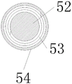
fig. 3 is a radial sectional view of the handle of fig. 1.
Detailed Description
The technical solutions in the embodiments of the present invention will be described clearly and completely with reference to the accompanying drawings in the embodiments of the present invention, and it is obvious that the described embodiments are only some embodiments of the present invention, not all embodiments. Based on the embodiments in the present invention, all other embodiments obtained by a person skilled in the art without creative work belong to the protection scope of the present invention.
Referring to fig. 1-3, the anti-collision wall modification platform convenient to move comprises a support 2 and a basket bucket, wherein the support 2 is horizontally arranged, one end of the support is vertically bent downwards, the other end of the support is connected with the basket bucket, a shaft lever at the bottom of a horizontal section 21 of the support is connected with a top roller 31 used for being in compression joint with the top surface of the anti-collision wall 1, and a shaft lever on a bending section 22 of the support is connected with an inner side roller 32 used for abutting against the inner side surface of the anti-collision wall.
Basket fill includes open- topped operation case 4, and 4 inner walls of operation case are pasted and are equipped with skid resistant course 41, and operation case 4 is equipped with two vertical connecting rods 45 towards the lateral wall top of crashproof wall 1, and two vertical connecting rods 45 are articulated with support 2 through round pin axle 46, and are connected with outside gyro wheel 33 through the axostylus axostyle on two vertical connecting rods 45, and the axis of outside gyro wheel 33 is on a parallel with the setting of inboard gyro wheel 32 axis. The axis of the top roller 31 is perpendicular to the extending direction of the impact wall 1 and the axis of the inner roller 32, respectively.
The lateral wall top of operation case 4 crashproof wall dorsad is equipped with two stiffener 44, and stiffener 44 constitutes the triangular structure with 4 lateral walls of vertical connecting rod 45 cooperation operation cases that correspond, and hinge 42 and guard plate 43 tip are passed through at the lateral wall top of operation case 4 crashproof wall dorsad articulated, are equipped with handle 5 on the guard plate 43, and under the hinged end of guard plate 43 was in the top state, handle 5 was located on the lateral wall that the operation case was kept away from to the guard plate.
The handle 5 comprises two lug plates 51, the two lug plates 51 are connected through a support rod 52, a sleeve 54 and a scroll spring 53 are sleeved outside the support rod 52, the scroll spring 53 is located in the sleeve 54, one end of the scroll spring is connected with the outer wall of the support rod 52, the other end of the scroll spring is connected with the inner wall of the sleeve 54, a pull rope 55 is wound outside the sleeve 54, one end of the pull rope is free, and the other end of the pull rope is fixedly connected with the outer wall of the sleeve.
When the decoration or the false seam cutting work of carrying out the crashproof wall, hang this device on the crashproof wall body: make the support horizontal segment earlier place at crashproof wall top surface, make the inboard gyro wheel of the section of bending and top gyro wheel contact crashproof wall inside surface and top surface respectively simultaneously, then rotate the basket through the round pin axle and fight for outside gyro wheel contact crashproof wall lateral surface on the basket was fought, then the staff gets into the operation incasement through the ladder of ascending a height, and operates crashproof wall. Meanwhile, another worker can drive the basket bucket to move along the anti-collision wall through the roller, so that the worker sequentially carries out continuous modification or false seam cutting operation on the whole anti-collision wall.
Because still be equipped with street lamp basis on the anticollision wall in succession, anticollision wall lateral surface is equipped with a lot of archs promptly, so work as the utility model discloses when removing to street lamp basis, can adopt two kinds of modes to solve: 1) workers leave the basket bucket, and the workers on the bridge face can rotate the basket bucket around the pin shaft to enable the utility model to cross the street lamp foundation; 2) the staff that the basket was fought rotates the guard plate to the pulling is the free end of stay cord on hand, makes the stay cord drive the sleeve and overcomes volute spring and rotate and make the stay cord extension, then gives the stay cord free end to the bridge floor staff on hand, and this staff nevertheless the basket through the stay cord pulling is fought and is rotated certain angle around the round pin axle, and the staff in the basket was fought simultaneously can promptly sell axle or operation case and prevent to overturn, until the utility model discloses cross the street lamp basis, then continue the operation, volute spring makes the sleeve reset to rotate and twine the stay cord again, prevents that the stay cord overlength from stumbling the foot.
After the workers finish the work in the same day and leave the work box, the protection plates can be turned over and the work box is covered, so that sundries are prevented from falling into the work box.