CN210457748U - Printing and dyeing sewage debris collection device - Google Patents
Printing and dyeing sewage debris collection device Download PDFInfo
- Publication number
- CN210457748U CN210457748U CN201921171566.5U CN201921171566U CN210457748U CN 210457748 U CN210457748 U CN 210457748U CN 201921171566 U CN201921171566 U CN 201921171566U CN 210457748 U CN210457748 U CN 210457748U
- Authority
- CN
- China
- Prior art keywords
- filter screen
- coagulating sedimentation
- sedimentation tank
- printing
- tank
- Prior art date
- Legal status (The legal status is an assumption and is not a legal conclusion. Google has not performed a legal analysis and makes no representation as to the accuracy of the status listed.)
- Expired - Fee Related
Links
- 238000004043 dyeing Methods 0.000 title claims abstract description 44
- 239000010865 sewage Substances 0.000 title claims abstract description 24
- 238000004062 sedimentation Methods 0.000 claims abstract description 68
- 230000001112 coagulating effect Effects 0.000 claims abstract description 64
- XLYOFNOQVPJJNP-UHFFFAOYSA-N water Substances O XLYOFNOQVPJJNP-UHFFFAOYSA-N 0.000 claims abstract description 62
- 238000005192 partition Methods 0.000 claims abstract description 15
- 230000007704 transition Effects 0.000 claims description 22
- 239000002351 wastewater Substances 0.000 claims description 19
- 238000001125 extrusion Methods 0.000 claims description 16
- 230000003014 reinforcing effect Effects 0.000 claims description 6
- 239000012535 impurity Substances 0.000 claims 9
- 239000004744 fabric Substances 0.000 abstract description 16
- 238000009941 weaving Methods 0.000 abstract description 6
- 238000011045 prefiltration Methods 0.000 abstract description 3
- 239000004753 textile Substances 0.000 description 8
- 230000015271 coagulation Effects 0.000 description 3
- 238000005345 coagulation Methods 0.000 description 3
- 230000000694 effects Effects 0.000 description 3
- 238000000034 method Methods 0.000 description 3
- 238000001179 sorption measurement Methods 0.000 description 3
- 238000007599 discharging Methods 0.000 description 2
- 230000005012 migration Effects 0.000 description 2
- 238000013508 migration Methods 0.000 description 2
- 239000000725 suspension Substances 0.000 description 2
- 244000025254 Cannabis sativa Species 0.000 description 1
- 235000012766 Cannabis sativa ssp. sativa var. sativa Nutrition 0.000 description 1
- 235000012765 Cannabis sativa ssp. sativa var. spontanea Nutrition 0.000 description 1
- 229920000742 Cotton Polymers 0.000 description 1
- 235000009120 camo Nutrition 0.000 description 1
- 235000005607 chanvre indien Nutrition 0.000 description 1
- 125000004122 cyclic group Chemical group 0.000 description 1
- 238000010586 diagram Methods 0.000 description 1
- 238000005868 electrolysis reaction Methods 0.000 description 1
- 239000000835 fiber Substances 0.000 description 1
- 239000011487 hemp Substances 0.000 description 1
- 238000009434 installation Methods 0.000 description 1
- 238000004519 manufacturing process Methods 0.000 description 1
- 239000000203 mixture Substances 0.000 description 1
- 230000003647 oxidation Effects 0.000 description 1
- 238000007254 oxidation reaction Methods 0.000 description 1
- 238000000746 purification Methods 0.000 description 1
- 230000002787 reinforcement Effects 0.000 description 1
- 239000007787 solid Substances 0.000 description 1
- 229910001220 stainless steel Inorganic materials 0.000 description 1
- 239000010935 stainless steel Substances 0.000 description 1
- 239000000126 substance Substances 0.000 description 1
- 238000004065 wastewater treatment Methods 0.000 description 1
Images

Landscapes
- Filtration Of Liquid (AREA)
Abstract
A printing and dyeing sewage sundry collecting device comprises a coagulating sedimentation tank, wherein a first water inlet and a first water outlet are formed in the coagulating sedimentation tank, a first collecting device is arranged at the water inlet end of the coagulating sedimentation tank, the first collecting device comprises a filter screen, the filter screen is fixed on the coagulating sedimentation tank, a sundry tank is arranged on one side of the coagulating sedimentation tank, a first partition plate is arranged between the coagulating sedimentation tank and the sundry tank, one end of the filter screen is in contact with the coagulating sedimentation tank, the other end of the filter screen is arranged at the top of the first partition plate, and a collecting bag is arranged in the sundry tank; the support that is the type of falling U is equipped with at the end of intaking of coagulating sedimentation pond, and the support includes two vertical first bracing pieces, is equipped with the horizontally pole that hangs at the top fixed connection of first bracing piece, is equipped with thrust unit on hanging the pole. The utility model discloses carry out the prefilter to printing and dyeing sewage, hold back and collect the weaving cloth that adulterates in the sewage of will printing and dyeing or other debris, the centralized processing of being convenient for reduces the probability that pipeline and equipment blockked up.
Description
Technical Field
The utility model relates to a technical field of sewage debris collecting device, concretely relates to printing and dyeing sewage debris collection device.
Background
The printing and dyeing wastewater is wastewater discharged by a printing and dyeing mill mainly processing cotton, hemp, chemical fibers and blended products thereof, more printing and dyeing wastewater is generated in the printing and dyeing process, and a printing and dyeing wastewater treatment device is required to treat the printing and dyeing wastewater so as to be recovered and realize cyclic utilization. The existing printing and dyeing sewage treatment device carries out coagulation sedimentation, oxidation, electrolysis, adsorption and purification treatment on printing and dyeing sewage, but a great deal of textile cloth or other sundries are likely to be doped in the printing and dyeing sewage, and during the treatment and the conveying process of the printing and dyeing sewage, pipelines and equipment are easily blocked, so that the equipment is damaged, great economic loss is caused, the treatment of the printing and dyeing sewage is influenced, and the production efficiency is reduced.
SUMMERY OF THE UTILITY MODEL
The utility model aims to provide a: the utility model provides a printing and dyeing sewage debris collection device carries out prefilter to printing and dyeing sewage, and weaving cloth or other debris that will mix in the printing and dyeing sewage are held back and are collected, and the centralized processing of being convenient for reduces the probability that pipeline and equipment blockked up.
The utility model discloses the technical scheme who takes does:
a printing and dyeing sewage sundry collecting device comprises a coagulating sedimentation tank, wherein a first water inlet and a first water outlet are formed in the coagulating sedimentation tank, a first collecting device is arranged at the water inlet end of the coagulating sedimentation tank and comprises a filter screen, the filter screen is fixed on the coagulating sedimentation tank, a sundry tank is arranged on one side of the coagulating sedimentation tank, a first partition plate is arranged between the coagulating sedimentation tank and the sundry tank, one end of the filter screen is in contact with the coagulating sedimentation tank, the other end of the filter screen is arranged at the top of the first partition plate, a collecting bag is arranged in the sundry tank, and the collecting bag is detachably and fixedly connected with the sundry tank; the support that is the type of falling U is equipped with at the end of intaking in coagulating sedimentation tank, the support includes two vertical first bracing pieces, coagulating sedimentation tank and debris pond set up between two first bracing pieces, top fixed connection at first bracing piece has the horizontally to hang the pole, be equipped with thrust unit on hanging the pole, thrust unit includes the lead screw, the lead screw tip rotates with first bracing piece to be connected, be fixed with first motor on one of them first bracing piece, the output shaft of first motor and the tip fixed connection of lead screw, threaded connection has the sleeve on the lead screw, be fixed with vertical decurrent connecting rod on the sleeve, bottom fixedly connected with push pedal device at the connecting rod, the bottom of push pedal device and the bottom contact of filter screen.
The push plate device comprises a curved push plate main body, wherein an opening of the push plate main body points to a sundry pool, a horizontal plate is fixed at the top end of the push plate main body, a slant plate which inclines downwards is fixed at the bottom end of the push plate main body, and the bottom end of the slant plate is in contact with the bottom of the filter screen.
And a plurality of reinforcing ribs are arranged at the joint of the connecting rod and the push plate device.
The sundries pool is internally provided with an extrusion device which is arranged outside the collecting bag, the extrusion device comprises symmetrical extrusion hydraulic rods, the fixed ends of the extrusion hydraulic rods are fixed in the sundries pool, and the free ends of the hydraulic rods are fixedly provided with extrusion plates.
The debris pond is provided with a water outlet, the coagulating sedimentation pond is provided with a second water inlet, the water outlet is higher than the second water inlet, the water outlet is communicated with the second water inlet through a water drainage pipe, and the water drainage pipe is provided with a one-way valve.
The cross section of filter screen is the L type, and the filter screen includes horizontal part and vertical portion, and the outer end of horizontal part is fixed on coagulating sedimentation pond.
The filter screen comprises a plurality of filter screen units, the end surfaces of adjacent filter screen units are attached, a sliding block is fixed at the outer end of the horizontal part of each filter screen unit, a protruding part is arranged on the side wall of the coagulating sedimentation tank, the protruding part is arranged along the width direction of the coagulating sedimentation tank, a slide way is arranged on the protruding part, the sliding block is matched with the slide way, and when the filter screen units are in a fixed state, the sliding block is fixed on the slide way through bolts; the first water inlet is arranged above the bulge; the first water inlet is the bar, and first water inlet is parallel with the horizontal part of filter screen.
A transition tank is arranged at the water outlet end of the coagulating sedimentation tank, a second partition plate is arranged between the coagulating sedimentation tank and the transition tank, and a first water outlet is arranged on the second partition plate; be equipped with in the transition pond and change the roller, change the width direction setting of roller along the transition pond, change the roller and rotate with the transition pond and be connected, be equipped with the adsorbed layer on changeing the roller, the shape of adsorbed layer suits with the shape of changeing the roller, is equipped with the second motor outside the transition pond, the output of second motor and the tip fixed connection who changes the roller.
A plurality of uniformly spaced second supporting rods are fixed in the coagulating sedimentation tank, the second supporting rods are vertically arranged, and the tops of the second supporting rods are in contact with the filter screen.
The connecting rod is a hydraulic rod or an electric push rod.
The utility model discloses the filter screen of the end of intaking of well coagulating sedimentation tank carries out the prefilter to printing and dyeing waste water, textile cloth or other debris with doping in the printing and dyeing sewage are held back to the filter screen on, thrust unit's first motor drives the lead screw and rotates, the lead screw will rotate and turn into telescopic horizontal migration, the sleeve drives the connecting rod and removes, the connecting rod drives the push pedal device and removes, textile cloth or other debris push away to the collection bag in debris pond on the push pedal device will filter screen, the workman centralized processing of being convenient for, reduce the probability that pipeline and equipment blockked up, and the work efficiency is improved.
The main body of the push plate device plays a main pushing role, the horizontal plate plays a shielding role, and the inclined plate is convenient for shoveling woven cloth or other sundries into the main body of the push plate; the reinforcing ribs play a role in reinforcement; the squeezing device is used for squeezing out water in the collecting bag, so that workers can conveniently handle the collecting bag; the drain pipe is used for discharging water in the sundries pool, and the one-way valve enables the water in the sundries pool to flow only into the coagulating sedimentation pool; the vertical part of the filter screen plays a role in shielding, and when more textile cloth or other sundries are accumulated on the horizontal part, the printing and dyeing sewage can flow out of the vertical part conveniently; the filter screen comprises a plurality of filter screen units, when one part of the filter screen units is damaged, only the corresponding filter screen unit needs to be replaced, the cost is saved, the replacement is convenient, the filter screen units move along the slide way through the slide blocks, and when the filter screen units are in a fixed state, the slide blocks are fixed on the slide way through bolts, so that the installation is convenient; the transition tank plays a transition role, and the adsorption layer is used for further adsorbing suspended matters in the printing and dyeing wastewater; the second supporting rod supports the filter screen; the connecting rod is hydraulic stem or electric putter, and the connecting rod is scalable, accomplishes to push away weaving cloth or other debris and pushes away to debris pond back when the push pedal device, and the connecting rod shrink, and the push pedal device of being convenient for resumes to initial position.
Drawings
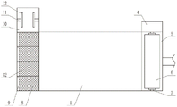
Fig. 1 is a schematic structural view of the present invention;
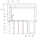
FIG. 2 is a partial cross-sectional view of FIG. 1;
FIG. 3 is a right side cross-sectional view of FIG. 1;
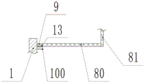
FIG. 4 is a schematic view of a connection structure of a filter screen and a coagulation sedimentation tank;
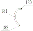
fig. 5 is a schematic structural diagram of the push plate device.
Detailed Description
As shown in fig. 1-5, a printing and dyeing sewage sundry collecting device comprises a coagulating sedimentation tank 1, a first water inlet 101 and a first water outlet are arranged on the coagulating sedimentation tank 1, a first collecting device is arranged at the water inlet end of the coagulating sedimentation tank 1, the first collecting device comprises a filter screen 8, the filter screen 8 can be made of stainless steel mesh or a plate made of concrete, a filter hole is arranged on the plate, the filter screen 8 is fixed on the coagulating sedimentation tank 1, the filter screen 8 is arranged along the width direction of the coagulating sedimentation tank 1, the filter screen 8 primarily filters printing and dyeing wastewater, textile cloth or other sundries doped in the printing and dyeing wastewater are intercepted on the filter screen 8, a sundry tank 10 is arranged at one side of the coagulating sedimentation tank 1, a first partition plate 20 is arranged between the coagulating sedimentation tank 1 and the sundry tank 10, the coagulating sedimentation tank 1 and the sundry tank 10 are separated by the first partition plate 20 and do not communicate with each other, one end of the filter screen 8 is in contact with the coagulating sedimentation tank 1, the other end of the filter screen 8 is arranged at the top of the first partition plate 20, a collecting bag is arranged in the sundries tank 10, the collecting bag can drain water outwards, a common woven bag can be adopted, the collecting bag is detachably and fixedly connected with the sundries tank 10, and the edge of the collecting bag can be fixed at the top of the sundries tank 10 through a screw; the water inlet end of the coagulating sedimentation tank 1 is provided with an inverted U-shaped bracket 3, the bracket 3 comprises two vertical first supporting rods 30, the coagulating sedimentation tank 1 and the sundries tank 10 are arranged between the two first supporting rods 30, namely, the coagulating sedimentation tank 1 and the sundries tank 10 span between the brackets 3, the top of each first supporting rod 30 is fixedly connected with a horizontal suspension rod 31, each suspension rod 31 is provided with a pushing device, each pushing device comprises a lead screw 15, the end part of each lead screw 15 is rotatably connected with the corresponding first supporting rod 30, a bearing can be arranged on each first supporting rod 30, each lead screw 15 is rotatably connected with the corresponding first supporting rod 30 through the corresponding bearing, one first supporting rod 30 is fixedly provided with the corresponding first motor 2, the output shaft of each first motor 2 is fixedly connected with the end part of each lead screw 15, the end part of each lead screw 15 extends out of the corresponding first supporting rod 30 and is fixedly connected with the output shaft of the corresponding motor, or the output shaft of each motor extends into the corresponding first supporting rod 30 and is fixedly, threaded connection has sleeve 14 on lead screw 15, be fixed with vertical decurrent connecting rod 16 on sleeve 14, bottom fixedly connected with push pedal device 18 at connecting rod 16, the bottom of push pedal device 18 and the bottom contact of filter screen 8, thrust unit's first motor 2 drives lead screw 15 and rotates, lead screw 15 turns into sleeve 14's horizontal migration with rotating, sleeve 14 drives connecting rod 16 and removes, connecting rod 16 drives push pedal device 18 and removes, push pedal device 18 pushes away weaving cloth or other debris on the filter screen 8 to the collection bag in debris pond 10, be convenient for workman centralized processing, reduce the probability that pipeline and equipment blockked up, and the work efficiency is improved.
The push plate device 18 is including being curved push plate main part 181, the directional debris pond 10 of opening of push plate main part 181, top at push plate main part 181 is fixed with horizontal plate 180, bottom mounting at push plate main part 181 has the decurrent hang plate 182 of slope, the bottom of hang plate 182 and the bottom contact of filter screen 8, push plate main part 181 of push plate device 18 plays main pushing effect, horizontal plate 180 plays the effect of sheltering from, the hang plate 182 is convenient for shoveling into push plate main part 181 weaving cloth or other debris.
A plurality of reinforcing ribs 17 are arranged at the joint of the connecting rod 16 and the push plate device 18, and the reinforcing ribs 17 play a reinforcing role.
Be equipped with extrusion device in debris pond 10, extrusion device is used for extruding the water in collecting the bag, and the workman of being convenient for handles the collection bag, and extrusion device sets up outside collecting the bag, and extrusion device includes the extrusion hydraulic stem 11 of symmetry, and the stiff end of extrusion hydraulic stem 11 is fixed in debris pond 10, is fixed with stripper plate 12 at the free end of hydraulic stem.
The debris pond 10 is provided with a water outlet, the coagulating sedimentation pond 1 is provided with a second water inlet, the water outlet is higher than the second water inlet, the water outlet is communicated with the second water inlet through a water discharge pipe, the water discharge pipe is used for discharging water in the debris pond 10, the water discharge pipe is provided with a one-way valve, and the one-way valve enables the water in the debris pond 10 to only flow into the coagulating sedimentation pond 1.
The cross section of filter screen 8 is the L type, and filter screen 8 includes horizontal part 80 and vertical portion 81, and the outer end of horizontal part 80 is fixed on coagulating sedimentation tank 1, and vertical portion 81 of filter screen 8 plays the effect of sheltering from, when piling up more weaving cloth or other debris on horizontal part 80, and the printing and dyeing sewage of being convenient for flows from vertical portion 81.
The filter screen 8 comprises a plurality of filter screen units 82, when one part of the filter screen units 82 is damaged, only the corresponding filter screen unit 82 needs to be replaced, the cost is saved, the replacement is convenient, the end surfaces of the adjacent filter screen units 82 are attached, a sliding block 9 is fixed at the outer end of a horizontal part 80 of each filter screen unit 82, a protruding part 100 is arranged on the side wall of the coagulating sedimentation tank 1, the protruding part 100 is arranged along the width direction of the coagulating sedimentation tank 1, a slide way 13 is arranged on the protruding part 100, the sliding block 9 is matched with the slide way 13, the sliding block 9 can move along the slide way 13 and is convenient to mount and dismount, and when the filter screen units 82 are in a fixed state, the; the first water inlet 101 is arranged above the boss 100; the first water inlet 101 is in a bar shape, and the first water inlet 101 is parallel to the horizontal part 80 of the filter screen 8.
A transition tank 5 is arranged at the water outlet end of the coagulating sedimentation tank 1, the transition tank 5 plays a role in transition, a second partition plate is arranged between the coagulating sedimentation tank 1 and the transition tank 5, and a first water outlet is arranged on the second partition plate; be equipped with in transition pond 5 and change roller 7, change roller 7 and set up along the width direction of transition pond 5, change roller 7 and transition pond 5 and rotate to be connected, be equipped with adsorbed layer 6 on changeing roller 7, adsorbed layer 6 can adopt the sponge, the shape of adsorbed layer 6 suits with the shape of changeing roller 7, adsorbed layer 6 is used for further adsorbing the suspended solid in the printing and dyeing wastewater, be equipped with second motor 4 outside transition pond 5, the output of second motor 4 and the tip fixed connection who changes roller 7.
A plurality of second supporting rods 19 which are evenly spaced are fixed in the coagulating sedimentation tank 1, the second supporting rods 19 are vertically arranged, and the tops of the second supporting rods 19 are in contact with the filter screen 8 to support the filter screen 8.
The connecting rod 16 is a hydraulic rod or an electric push rod, the connecting rod 16 is telescopic, and after the push plate device 18 pushes the woven cloth or other sundries into the sundry pool 10, the connecting rod 16 is contracted, so that the push plate device 18 can be conveniently restored to the initial position.
When the device is used, printing and dyeing sewage enters the coagulating sedimentation tank 1 through the first water inlet 101, the printing and dyeing sewage is preliminarily filtered through the filter screen 8, textile cloth or other sundries doped in the printing and dyeing sewage are intercepted on the filter screen 8, when the textile cloth or other sundries on the filter screen 8 reach a certain amount, the first motor 2 is powered on, the first motor 2 works, the first motor 2 of the pushing device drives the screw rod 15 to rotate, the screw rod 15 converts the rotation into horizontal movement of the sleeve 14, the sleeve 14 drives the connecting rod 16 to move, the connecting rod 16 drives the push plate device 18 to move, the push plate device 18 pushes the textile cloth or other sundries on the filter screen 8 into a collecting bag of the sundries tank 10, the first motor 2 controls the screw rod 15 to rotate reversely, the pushing device returns to the initial position, when the sundries in the collecting bag reach a certain amount, the extruding device in the sundries tank, a new collecting bag is replaced, and the water in the sundries tank 10 flows into the coagulating sedimentation tank 1 through a drain pipe; when the coagulation sedimentation tank 1 finishes sedimentation and the next process drains water, the second motor 4 is powered on, the second motor 4 drives the rotary roller 7 and the adsorption layer 6 to rotate, and suspended matters in the printing and dyeing wastewater are further adsorbed.
The hydraulic rod of the utility model can be connected with a hydraulic system, and a general hydraulic system is adopted, including an oil tank, a hydraulic pump and a reversing valve, the hydraulic pump is connected with the oil tank, and the hydraulic pump is connected with the hydraulic rod through the reversing valve, which is the prior art and is not described again; the hydraulic rod can also adopt an electric hydraulic rod.
The above-mentioned embodiment is right the utility model discloses an explanation, it is not right the utility model discloses a limited, any right the scheme after the simple transform of the utility model all belongs to the protection scope of the utility model.
Claims (10)
1. The utility model provides a printing and dyeing sewage debris collection device, includes the coagulating sedimentation pond, is equipped with first water inlet and first delivery port on the coagulating sedimentation pond, its characterized in that: a first collecting device is arranged at the water inlet end of the coagulating sedimentation tank, the first collecting device comprises a filter screen, the filter screen is fixed on the coagulating sedimentation tank, a sundry tank is arranged on one side of the coagulating sedimentation tank, a first partition plate is arranged between the coagulating sedimentation tank and the sundry tank, one end of the filter screen is in contact with the coagulating sedimentation tank, the other end of the filter screen is arranged at the top of the first partition plate, a collecting bag is arranged in the sundry tank, and the collecting bag is detachably and fixedly connected with the sundry tank; the support that is the type of falling U is equipped with at the end of intaking in coagulating sedimentation tank, the support includes two vertical first bracing pieces, coagulating sedimentation tank and debris pond set up between two first bracing pieces, top fixed connection at first bracing piece has the horizontally to hang the pole, be equipped with thrust unit on hanging the pole, thrust unit includes the lead screw, the lead screw tip rotates with first bracing piece to be connected, be fixed with first motor on one of them first bracing piece, the output shaft of first motor and the tip fixed connection of lead screw, threaded connection has the sleeve on the lead screw, be fixed with vertical decurrent connecting rod on the sleeve, bottom fixedly connected with push pedal device at the connecting rod, the bottom of push pedal device and the bottom contact of filter screen.
2. The printing and dyeing wastewater impurity collecting device according to claim 1, characterized in that: the push plate device comprises a curved push plate main body, wherein an opening of the push plate main body points to a sundry pool, a horizontal plate is fixed at the top end of the push plate main body, a slant plate which inclines downwards is fixed at the bottom end of the push plate main body, and the bottom end of the slant plate is in contact with the bottom of the filter screen.
3. The printing and dyeing wastewater impurity collecting device according to claim 2, characterized in that: and a plurality of reinforcing ribs are arranged at the joint of the connecting rod and the push plate device.
4. The printing and dyeing wastewater impurity collecting device according to claim 1, characterized in that: the sundries pool is internally provided with an extrusion device which is arranged outside the collecting bag, the extrusion device comprises symmetrical extrusion hydraulic rods, the fixed ends of the extrusion hydraulic rods are fixed in the sundries pool, and the free ends of the hydraulic rods are fixedly provided with extrusion plates.
5. The printing and dyeing wastewater impurity collecting device according to claim 4, characterized in that: the debris pond is provided with a water outlet, the coagulating sedimentation pond is provided with a second water inlet, the water outlet is higher than the second water inlet, the water outlet is communicated with the second water inlet through a water drainage pipe, and the water drainage pipe is provided with a one-way valve.
6. The printing and dyeing wastewater impurity collecting device according to claim 1, characterized in that: the cross section of filter screen is the L type, and the filter screen includes horizontal part and vertical portion, and the outer end of horizontal part is fixed on coagulating sedimentation pond.
7. The printing and dyeing wastewater impurity collecting device according to claim 6, characterized in that: the filter screen comprises a plurality of filter screen units, the end surfaces of adjacent filter screen units are attached, a sliding block is fixed at the outer end of the horizontal part of each filter screen unit, a protruding part is arranged on the side wall of the coagulating sedimentation tank, the protruding part is arranged along the width direction of the coagulating sedimentation tank, a slide way is arranged on the protruding part, the sliding block is matched with the slide way, and when the filter screen units are in a fixed state, the sliding block is fixed on the slide way through bolts; the first water inlet is arranged above the bulge; the first water inlet is the bar, and first water inlet is parallel with the horizontal part of filter screen.
8. The printing and dyeing wastewater impurity collecting device according to claim 1, characterized in that: a transition tank is arranged at the water outlet end of the coagulating sedimentation tank, a second partition plate is arranged between the coagulating sedimentation tank and the transition tank, and a first water outlet is arranged on the second partition plate; be equipped with in the transition pond and change the roller, change the width direction setting of roller along the transition pond, change the roller and rotate with the transition pond and be connected, be equipped with the adsorbed layer on changeing the roller, the shape of adsorbed layer suits with the shape of changeing the roller, is equipped with the second motor outside the transition pond, the output of second motor and the tip fixed connection who changes the roller.
9. The printing and dyeing wastewater impurity collecting device according to claim 1, characterized in that: a plurality of uniformly spaced second supporting rods are fixed in the coagulating sedimentation tank, the second supporting rods are vertically arranged, and the tops of the second supporting rods are in contact with the filter screen.
10. The printing and dyeing wastewater impurity collecting device according to claim 1, characterized in that: the connecting rod is a hydraulic rod or an electric push rod.
Priority Applications (1)
| Application Number | Priority Date | Filing Date | Title |
|---|---|---|---|
| CN201921171566.5U CN210457748U (en) | 2019-07-24 | 2019-07-24 | Printing and dyeing sewage debris collection device |
Applications Claiming Priority (1)
| Application Number | Priority Date | Filing Date | Title |
|---|---|---|---|
| CN201921171566.5U CN210457748U (en) | 2019-07-24 | 2019-07-24 | Printing and dyeing sewage debris collection device |
Publications (1)
| Publication Number | Publication Date |
|---|---|
| CN210457748U true CN210457748U (en) | 2020-05-05 |
Family
ID=70447279
Family Applications (1)
| Application Number | Title | Priority Date | Filing Date |
|---|---|---|---|
| CN201921171566.5U Expired - Fee Related CN210457748U (en) | 2019-07-24 | 2019-07-24 | Printing and dyeing sewage debris collection device |
Country Status (1)
| Country | Link |
|---|---|
| CN (1) | CN210457748U (en) |
Cited By (2)
| Publication number | Priority date | Publication date | Assignee | Title |
|---|---|---|---|---|
| CN114100246A (en) * | 2021-10-12 | 2022-03-01 | 孙武 | A kind of high-efficiency treatment machine for sewage decolorization of printing and dyeing textiles |
| CN114669124A (en) * | 2022-04-13 | 2022-06-28 | 中建八局第一建设有限公司 | A maintenance water recycling device |
-
2019
- 2019-07-24 CN CN201921171566.5U patent/CN210457748U/en not_active Expired - Fee Related
Cited By (4)
| Publication number | Priority date | Publication date | Assignee | Title |
|---|---|---|---|---|
| CN114100246A (en) * | 2021-10-12 | 2022-03-01 | 孙武 | A kind of high-efficiency treatment machine for sewage decolorization of printing and dyeing textiles |
| CN114100246B (en) * | 2021-10-12 | 2023-08-25 | 泗县微腾知识产权运营有限公司 | A high-efficiency treatment machine for printing and dyeing textile supporting sewage decolorization |
| CN114669124A (en) * | 2022-04-13 | 2022-06-28 | 中建八局第一建设有限公司 | A maintenance water recycling device |
| CN114669124B (en) * | 2022-04-13 | 2023-11-24 | 中建八局第一建设有限公司 | Maintenance water cyclic utilization device |
Similar Documents
| Publication | Publication Date | Title |
|---|---|---|
| CN207619157U (en) | A kind of sewage-treatment plant being conveniently replaceable filter screen | |
| CN204910966U (en) | Energy -conserving microstrainer | |
| CN217773414U (en) | Industrial wastewater treatment equipment capable of preventing blockage | |
| CN210457850U (en) | Be used for sewage treatment plant of printing and dyeing mill | |
| CN219481754U (en) | Deep bed type filtering device | |
| CN216855802U (en) | Sewage multi-stage treatment device for hydraulic engineering | |
| CN111170379A (en) | Domestic sewage garbage filtering, collecting and treating device | |
| CN111998166B (en) | Municipal administration is with drainage pipe of being convenient for clear up rubbish | |
| CN213253210U (en) | Pre-filtering device for sewage treatment | |
| CN212982506U (en) | Sediment cleaning device for sewage treatment | |
| CN210229295U (en) | Sewage treatment plant is used in municipal garden | |
| CN109137834B (en) | River surge purification treatment system | |
| CN223675476U (en) | A municipal drainage device | |
| CN222131216U (en) | Pipeline filter | |
| CN220768286U (en) | Anti-blocking device for building drainage pipe | |
| CN219615044U (en) | Groundwater pollution filtration purifier | |
| CN220328073U (en) | Municipal administration water supply and drainage filter equipment | |
| CN221142641U (en) | Road surface drainage device | |
| CN220598554U (en) | Anti-blocking device for foundation pit dewatering | |
| CN223158983U (en) | A sewage filtration structure for a shaftless screw conveyor | |
| CN219783960U (en) | Sewage filtering device for bridge construction site | |
| CN219449338U (en) | Advanced treatment device for reclaimed water recycling | |
| CN213803362U (en) | Novel environmental protection landscape sewage treatment device | |
| CN218952392U (en) | Water collection well ponding processing apparatus | |
| CN219558974U (en) | Waste water recovery device used in green building construction |
Legal Events
| Date | Code | Title | Description |
|---|---|---|---|
| GR01 | Patent grant | ||
| GR01 | Patent grant | ||
| CF01 | Termination of patent right due to non-payment of annual fee |
Granted publication date: 20200505 |
|
| CF01 | Termination of patent right due to non-payment of annual fee |