CN210454829U - Quick jacking resetting device for derailed vehicle - Google Patents
Quick jacking resetting device for derailed vehicle Download PDFInfo
- Publication number
- CN210454829U CN210454829U CN201921427058.9U CN201921427058U CN210454829U CN 210454829 U CN210454829 U CN 210454829U CN 201921427058 U CN201921427058 U CN 201921427058U CN 210454829 U CN210454829 U CN 210454829U
- Authority
- CN
- China
- Prior art keywords
- lifting
- oil cylinder
- bolster
- translation
- cylinder
- Prior art date
- Legal status (The legal status is an assumption and is not a legal conclusion. Google has not performed a legal analysis and makes no representation as to the accuracy of the status listed.)
- Expired - Fee Related
Links
- 238000005520 cutting process Methods 0.000 claims description 4
- 238000010276 construction Methods 0.000 abstract description 11
- 229910000831 Steel Inorganic materials 0.000 description 7
- 239000010959 steel Substances 0.000 description 7
- 238000000034 method Methods 0.000 description 5
- 238000003466 welding Methods 0.000 description 5
- 238000003860 storage Methods 0.000 description 4
- 206010012411 Derailment Diseases 0.000 description 1
- 208000027418 Wounds and injury Diseases 0.000 description 1
- 230000009286 beneficial effect Effects 0.000 description 1
- 230000006378 damage Effects 0.000 description 1
- 230000007547 defect Effects 0.000 description 1
- 208000014674 injury Diseases 0.000 description 1
- 238000009434 installation Methods 0.000 description 1
- 238000002360 preparation method Methods 0.000 description 1
Images


Landscapes
- Vehicle Cleaning, Maintenance, Repair, Refitting, And Outriggers (AREA)
Abstract
The utility model discloses a rapid jacking and resetting device for derailed vehicles, which is used for rapid re-rail of derailed vehicles and comprises a bolster, a lifting walking device, a lifting beam, a translation oil cylinder, an oil cylinder bracket and a counter-force supporting plate; the bolster level is erect on two tracks, and two lifting traveling devices establish on the bolster, it establishes on two lifting traveling devices to rise to lift the roof beam, it lifts the bearing and is connected with the derailment vehicle through the inboard bearing of lifting to rise to lift the roof beam, the connection can be dismantled in the bolster outside to the hydro-cylinder bracket, carries on the back mutually and sets up two, the connection can be dismantled in the lifting traveling device outside to the counter-force fagging, the translation hydro-cylinder is established on the hydro-cylinder bracket, and two translation hydro-cylinders set up back mutually. The utility model discloses a lift running gear will derail the vehicle jacking back, realize through the translation hydro-cylinder that the derail vehicle moves on the translation track that the bolster founded, realize quick, safe, steady the reseing of derail vehicle, greatly reduce intensity of labour, effectual promotion efficiency of construction.
Description
Technical Field
The utility model relates to a vehicle derails technical field that resets, concretely relates to quick jacking resetting means of derailed vehicle.
Background
The storage battery car is the main horizontal transport means in the tunnel, along with shield tunnel slope is bigger and bigger, for satisfying the storage battery car that horizontal transport capacity needs to have big traction force, just causes the storage battery car tonnage bigger and bigger, and this is more and more high to the rail requirement of laying temporarily in the tunnel, and the derailment risk increase of storage battery car in the tunnel.
Once the vehicle derails, the vehicle needs to be repaired and reset as soon as possible, generally, a hydraulic jack is adopted to jack up the derailed vehicle, then the derailed vehicle is slowly translated by using the jack or a chain block, but the translation difficulty is increased along with the increase of the tonnage of the battery car, and the movement is difficult. When the movable hand-pulled hoist of the jack is adopted for translation, normal transportation can be recovered generally in more than two hours, the efficiency is low, the deflection is extremely easy to generate, the translation process is not stable, the translation amount is not easy to control, secondary accidents are easily caused, personal injury occurs, and great potential safety hazards exist. The utility model provides a quick jacking resetting means of derailed vehicle overcomes above-mentioned defect.
SUMMERY OF THE UTILITY MODEL
The utility model provides a quick jacking resetting means of derailed vehicle has simple structure, the convenient advantage of dismouting to the work progress is swift reliable, effectively promotes the efficiency of construction, guarantees construction safety.
The utility model provides a technical scheme that above-mentioned technical problem adopted is:
a derailed vehicle fast jacking reset device is used for fast rerailing of derailed vehicles, the front and the back of the derailed vehicle are respectively provided with a set of device, which comprises a bolster, a lifting walking device, a lifting beam, a translation oil cylinder, an oil cylinder bracket and a counter-force supporting plate; the bolster is horizontally erected on the two rails and is perpendicular to the rails, the lifting traveling devices are arranged on the bolster and are arranged at intervals, the lifting beams are arranged on the two lifting traveling devices and are connected with a derailing vehicle through lifting bearings on the inner sides, the oil cylinder brackets are detachably connected to the outer sides of the bolster and are arranged oppositely between the two lifting traveling devices, the counter-force supporting plates are detachably connected to the outer sides of the lifting traveling devices and are arranged in one-to-one correspondence with the lifting traveling devices, the translation oil cylinders are arranged on the oil cylinder brackets and are arranged in one-to-one correspondence with the oil cylinder brackets, the two ends of the translation oil cylinders are respectively connected with the oil cylinder brackets and the counter-force supporting plates, one of the translation oil cylinders is arranged oppositely, and the other translation oil cylinder is in an extending state;
the lifting traveling device comprises a jacking oil cylinder, a traveling telescopic oil cylinder, traveling wheels and an outer frame; the outer frame is upper and lower open-ended standpipe, jacking cylinder, walking telescopic cylinder and walking wheel are established in the outer frame from top to bottom in proper order, jacking cylinder's the vertical upwards of direction of extension, walking telescopic cylinder's the vertical downwards of direction of extension, the walking wheel is connected on walking telescopic cylinder's piston rod.
Further, the bolster includes main fagging and locating plate, the same and parallel arrangement of main fagging and locating plate length, the locating plate is fixed in the main fagging side, and the interval is equipped with the slot on its length direction, the hydro-cylinder bracket can dismantle the connection on the bolster through inserting in the slot.
Furthermore, the lifting beam comprises two sleeves and a main beam, the two sleeves are respectively positioned at two ends of the main beam, and the lifting support is arranged on the inner side of the main beam; the opening of the sleeve is downward, and the upper end of the lifting traveling device is arranged in the sleeve; the lifting support is horizontally arranged, and the inner end of the lifting support is fixed on the main beam.
Furthermore, the slots are arranged in pairs, and the slots of each pair are uniformly spaced.
Further, the hydro-cylinder bracket is parallel arrangement's platform, and its inboard is equipped with the cutting, the cutting sets up in pairs to corresponding with the slot, the hydro-cylinder bracket outside and left side are equipped with the baffle, translation hydro-cylinder level is established on the hydro-cylinder bracket, is located the inboard of baffle.
Furthermore, the reaction supporting plate is horizontally arranged, and the inner side of the reaction supporting plate is provided with an inserting strip which is detachably connected to the outer frame.
Furthermore, the walking wheels are connected to a piston rod of the walking telescopic oil cylinder through a walking wheel fixing frame, and the walking wheels move left and right along the main supporting plate.
Furthermore, the outer frame is a square tube, a slot is formed in the side face, perpendicular to the traveling direction of the traveling wheel, of the outer frame, and the inserting strips of the counter-force supporting plate are detachably connected into the slot in the outer frame.
And the lifting traveling device and the translation oil cylinder are connected with the hydraulic pump station and are controlled to act through the hydraulic pump station.
The utility model discloses beneficial effect as follows:
the lifting traveling device is arranged to realize the jacking of the derailed vehicle, and the translation oil cylinder is utilized to gradually move the derailed vehicle to the upper part of the track, so that the stable jacking and translation of the derailed vehicle are realized, and the construction safety and the construction efficiency are ensured;
the bolster is arranged to construct a moving plane, so that the stability of the derailed vehicle in the translation process is guaranteed, and the safety is higher by utilizing the rail support;
the stable movement of the derailed vehicle is realized by the matching of the translation oil cylinders and the travelling wheels, and the two translation oil cylinders are symmetrically arranged to drive the derailed vehicle to translate, so that the vehicle can uniformly translate, and secondary accidents caused by uneven stress are avoided;
the combined structure is adopted, the assembly, disassembly and transportation are convenient, the installation preparation time of the device is effectively shortened, the derailed vehicle can be quickly and effectively reset by using the device, and the construction efficiency is effectively improved;
adopt hydraulic power unit to unify accurate control, reduce the construction degree of difficulty, improve the efficiency of construction to effectively reduce artifical direct operation's potential safety hazard.
Drawings
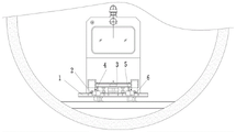
FIG. 1 is a front view of the utility model in use;
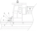
FIG. 2 is a side view of the utility model in use;
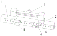
FIG. 3 is a front view of the overall structure of the present invention;
FIG. 4 is a schematic view of the bolster structure of the present invention;
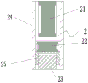
fig. 5 is a sectional view of the lifting and traveling device of the present invention;
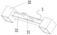
FIG. 6 is a schematic view of the lifting beam structure of the present invention;
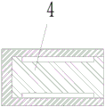
fig. 7 is a sectional view of the translation cylinder of the present invention;
fig. 8 is a schematic structural view of the oil cylinder bracket of the present invention;
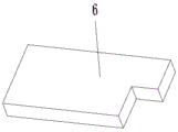
fig. 9 is a schematic view of the structure of the reaction supporting plate of the present invention.
Reference numerals: 1-bolster, 11-main supporting plate, 12-positioning plate, 13-slot, 2-lifting walking device, 21-jacking oil cylinder, 22-walking telescopic oil cylinder, 23-walking wheel, 24-outer frame, 25-walking wheel fixing frame, 3-lifting beam, 31-lifting bearing, 32-sleeve, 33-main beam, 4-translation oil cylinder, 5-oil cylinder bracket and 6-counterforce supporting plate.
Detailed Description
The technical solutions in the embodiments of the present invention will be described clearly and completely with reference to the accompanying drawings, and obviously, the described embodiments are only some embodiments, not all embodiments, of the present invention. Based on the embodiments in the present invention, all other embodiments obtained by a person skilled in the art without creative work belong to the protection scope of the present invention.
In the description of this patent, it is to be understood that the terms "center," "upper," "lower," "front," "rear," "left," "right," "vertical," "horizontal," "top," "bottom," "inner," "outer," and the like are used in the orientations and positional relationships indicated in the drawings for the convenience of describing the patent and for the simplicity of description, and are not intended to indicate or imply that the referenced devices or elements must have a particular orientation, be constructed and operated in a particular orientation, and are not to be considered limiting of the patent.
As shown in fig. 1, 2 and 3, a rapid jacking and resetting device for a derailed vehicle is used for rapid re-railing of the derailed vehicle, and the front and the rear of the derailed vehicle are respectively provided with one set, which comprises a bolster 1, a lifting and travelling device 2, a lifting beam 3, a translation oil cylinder 4, an oil cylinder bracket 5 and a counterforce supporting plate 6; the bolster 1 is horizontally erected on two rails and is perpendicular to the rails, the lifting traveling devices 2 are arranged on the bolster 1 at intervals, the lifting beams 3 are arranged on the two lifting traveling devices 2, the lifting beams 3 are connected with a derailed vehicle through lifting supports 31 on the inner sides, the oil cylinder brackets 5 are detachably connected to the outer side of the bolster 1 and are oppositely arranged and located between the two lifting traveling devices 2, and the counter-force supporting plates 6 are detachably connected to the outer sides of the lifting traveling devices 2 and are in one-to-one correspondence with the lifting traveling devices 2;
the translation oil cylinders 4 are arranged on the oil cylinder bracket 5 and are in one-to-one correspondence with the oil cylinder bracket 5, two ends of the translation oil cylinders are respectively connected with the oil cylinder bracket 5 and the counterforce supporting plate 6, the two translation oil cylinders 4 are arranged in a back-to-back manner, one translation oil cylinder is in an extending state, and the other translation oil cylinder is in a contracting state; the derailed vehicle is pushed and pulled synchronously by the two translation oil cylinders 4 which are arranged back to back, so that the stability of the movement process of the derailed vehicle is ensured, and the walking wheels 23 are ensured to stably move on the main supporting plate 11.
After the derailed vehicle is jacked through the lifting traveling device 2, the derailed vehicle moves on the translation track constructed by the bolster 1 through the cooperation of the translation oil cylinder 4 and the walking wheel 23, so that the derailed vehicle is quickly, safely and stably reset, the labor intensity is greatly reduced, and the construction efficiency is effectively improved.
As shown in fig. 5, the lifting and traveling device 2 includes a lifting cylinder 21, a traveling telescopic cylinder 22, a traveling wheel 23 and an outer frame 24; outer frame 24 is upper and lower open-ended standpipe, jacking cylinder 21, walking telescopic cylinder 22 and walking wheel 23 from top to bottom establish in outer frame 24 in proper order, jacking cylinder 21's the vertical upwards of direction of extension, walking telescopic cylinder 22's the vertical downwards of direction of extension, walking wheel 23 is connected on walking telescopic cylinder 22's piston rod.
Preferably, the outer frame 24 is formed by welding steel plates with the thickness of 20mm, the height of the outer frame is 380mm, and the walking wheels 23 are round steel with the outer diameter of 80 mm.
As shown in fig. 4, further, the bolster 1 includes a main supporting plate 11 and a positioning plate 12, the main supporting plate 11 and the positioning plate 12 have the same length and are arranged in parallel, the positioning plate 12 is fixed on the side of the main supporting plate 11, slots 13 are arranged in the length direction at intervals, and the oil cylinder bracket 5 is detachably connected to the bolster 1 by being inserted into the slots 13. Preferably, the main supporting plate 11 is made of 200 h-shaped steel with the length of 2m, the positioning plate 12 is made of a steel plate with the thickness of 10mm, and the main supporting plate 11 and the positioning plate 12 are connected through welding.
As shown in fig. 7, further, the lifting beam 3 includes two sleeves 32 and two main beams 33, the two sleeves 32 are respectively located at two ends of the main beam 33, and the lifting support 31 is located inside the main beam 33; the sleeve 32 is opened downwards, and the upper end of the lifting travelling device 2 is arranged in the sleeve 32; the lifting support 31 is arranged horizontally and its inner end is fixed to the main beam 33. Preferably, the main beam 33 is made of 100 h-shaped steel with the length of 1m, the center distance between the two sleeves 32 is 1040mm, the sleeves 32 are made of 10mm thick steel plates through welding, and the sleeves 32 and the lifting supports 31 are connected with the main beam 33 through welding.
Furthermore, a through hole is arranged in the middle of the lifting support 31 and is connected with an interface of the derailed vehicle through a pin shaft.
Further, as shown in fig. 4, the slots 13 are arranged in pairs, and each pair of slots 13 is arranged at a uniform interval.
Further, the interval between two adjacent pairs of slots 13 is the movement stroke of one translation cylinder 4. Preferably, the movement stroke is 100 mm. Through the translation many times of small distance, when having avoided the translation of single large-distance, the direction skew that counter-force fagging 6 leads to because of the atress, and then leads to walking wheel 23 and main fagging 11 to break away from secondary accident that appears to adopt short stroke translation hydro-cylinder 4 to effectively reduce its volume, conveniently transport and operate, and save cost.
As shown in fig. 7 and 8, further, the oil cylinder bracket 5 is a platform arranged in parallel, the inner side of the oil cylinder bracket is provided with inserting strips, the inserting strips are arranged in pairs and correspond to the inserting grooves 13, the outer side and the left side of the oil cylinder bracket 5 are provided with baffles, and the translation oil cylinder 4 is horizontally arranged on the oil cylinder bracket 5 and is positioned on the inner side of the baffles. Preferably, the oil cylinder bracket 5 is formed by welding steel plates with the thickness of 20 mm.
Furthermore, the two ends of the translation oil cylinder 4 are connected with the oil cylinder bracket 5 and the counter-force supporting plate 6 through pin shafts.
As shown in fig. 9, the reaction strut 6 is horizontally disposed, has a plug inside, and is detachably connected to the outer frame 24 through the plug.
As shown in fig. 5, further, the walking wheel 23 is connected to a piston rod of the walking telescopic cylinder 22 through a walking wheel fixing frame 25, and the walking wheel 23 moves left and right along the main supporting plate 11.
As shown in fig. 5, the outer frame 24 is a square tube, and a slot is formed on a side surface of the square tube perpendicular to the traveling direction of the traveling wheels 23, and the insert of the reaction bracing plate 6 is detachably connected in the slot on the outer frame 24.
And further, the lifting traveling device 2 and the translation oil cylinder 4 are connected with the hydraulic pump station, and the actions of the lifting traveling device and the translation oil cylinder are controlled by the hydraulic pump station. The hydraulic pump station is used for remotely controlling the action of the hydraulic cylinder, so that the situation that constructors are in close contact with derailed vehicles for construction is avoided, the operation is safer, unified control is adopted, the operation is more convenient, and the construction process is fast, stable and accurate.
A method of using a derailed vehicle reset device, comprising the steps of:
s1, laying the bolster 1: laying the bolster 1 on a track to ensure the bolster is vertical to the track;
s2, placing and adjusting the lifting and traveling device 2: placing the lifting traveling devices 2 on the bolster 1, ensuring that the traveling direction of the traveling wheels 23 is consistent with the length direction of the bolster 1, and adjusting the distance between the two lifting traveling devices 2 to be consistent with the distance between the two sleeves 32 of the lifting beam 3;
s3, placing the lifting beam 3: erecting a lifting beam 3 on the two lifting traveling devices 2, and translating the bolster 1 to enable a lifting bearing 31 to be connected with the derailed vehicle and to be fastened;
s4, mounting and connecting the translation oil cylinder 4: inserting an oil cylinder bracket 5 on the bolster 1, inserting a counterforce supporting plate 6 on the lifting walking device 2, placing a translation oil cylinder 4 on the oil cylinder bracket 5, and fixing two ends of the translation oil cylinder with the oil cylinder bracket 5 and the counterforce supporting plate 6;
s5, jacking the derailed vehicle: operating a hydraulic pump station to control two jacking oil cylinders 21 to synchronously extend out, and jacking the wheel part of the derailed vehicle to be higher than the rail;
s6, extending the walking wheels 23: operating a hydraulic pump station to control the two walking telescopic oil cylinders 22 to synchronously extend, and extending the walking wheels 23 out of the outer frame 24 and contacting with the main supporting plate 11;
s7, translating the derailed vehicle: operating a hydraulic pump station to control the two translation oil cylinders 4 to synchronously act, so that the translation oil cylinders 4 in the extending state are contracted, the translation oil cylinders 4 in the contracting state are extended, and the derailed vehicle is driven to translate to a position right above the track, so that the wheel part of the derailed vehicle is aligned with the track;
s8, resetting the derailed vehicle: and operating the hydraulic pump station to control the two walking telescopic oil cylinders 22 to synchronously contract, placing the derailed vehicle on the track, and dismantling the device after the derailed vehicle is in place.
Further, in the step S4, when two translation cylinders 4 are provided, the piston rod of the translation cylinder 4 in the contracted state faces the moving direction of the derailed vehicle, and the piston rod of the translation cylinder 4 in the extended state faces away from the moving direction of the derailed vehicle.
Further, in step S7, after the translation cylinder 4 moves for a stroke, the walking wheel 23 is retracted, so that the outer frame 24 contacts the bolster 1, the combination of the translation cylinder 4 and the cylinder bracket 5 is removed and moved to the next pair of slots 13, then the walking wheel 23 is extended out and the translation cylinder 4 is controlled to continue to translate the derailed vehicle, and the above operations are repeated until the derailed vehicle translates to a position right above the track.
Further, when only the front wheels of the derailed vehicle are derailed, only one set of device is used to be placed in front of the derailed vehicle and operated according to the above operation steps.
It is obvious to a person skilled in the art that the invention is not restricted to details of the above-described exemplary embodiments, but that it can be implemented in other specific forms without departing from the spirit or essential characteristics of the invention. The present embodiments are therefore to be considered in all respects as illustrative and not restrictive, the scope of the invention being indicated by the appended claims rather than by the foregoing description, and all changes which come within the meaning and range of equivalency of the claims are therefore intended to be embraced therein, and any reference signs in the claims are not intended to be construed as limiting the claim concerned.
Claims (9)
1. A rapid jacking and resetting device for a derailed vehicle is used for rapid re-railing of the derailed vehicle and is characterized in that the front and the back of the derailed vehicle are respectively provided with one set, and each set comprises a bolster (1), a lifting and travelling device (2), a lifting beam (3), a translation oil cylinder (4), an oil cylinder bracket (5) and a counter-force supporting plate (6); the bolster (1) is horizontally erected on two rails and is vertical to the rails, the two lifting traveling devices (2) are arranged on the bolster (1) at intervals, the two lifting beams (3) are arranged on the two lifting traveling devices (2), the lifting beams (3) are connected with a derailing vehicle through lifting supports (31) on the inner sides, the oil cylinder brackets (5) are detachably connected to the outer sides of the bolster (1) and are oppositely arranged and are positioned between the two lifting traveling devices (2), the counterforce supporting plates (6) are detachably connected to the outer sides of the lifting traveling devices (2) and are arranged corresponding to the lifting traveling devices (2), the translation oil cylinders (4) are arranged on the oil cylinder brackets (5) and are arranged corresponding to the oil cylinder brackets (5) one by one, the two ends of the translation oil cylinders are respectively connected with the oil cylinder brackets (5) and the counterforce supporting plates (6), and the two translation oil cylinders (4) are oppositely arranged, one in an extended state and the other in a retracted state;
the lifting walking device (2) comprises a jacking oil cylinder (21), a walking telescopic oil cylinder (22), a walking wheel (23) and an outer frame (24); outer frame (24) are upper and lower open-ended standpipe, jacking cylinder (21), walking telescopic cylinder (22) and walking wheel (23) are established in outer frame (24) from top to bottom in proper order, the vertical upwards of the direction of extension of jacking cylinder (21), the direction of extension of walking telescopic cylinder (22) is vertical downwards, walking wheel (23) are connected on the piston rod of walking telescopic cylinder (22).
2. The derailed vehicle fast jacking reset device according to claim 1, wherein: bolster (1) is including main fagging (11) and locating plate (12), main fagging (11) and locating plate (12) length are the same and parallel arrangement, locating plate (12) are fixed in main fagging (11) side, and the interval is equipped with slot (13) on its length direction, oil cylinder bracket (5) can dismantle the connection on bolster (1) through inserting in slot (13).
3. The derailed vehicle fast jacking reset device according to claim 1, wherein: the lifting beam (3) comprises two sleeves (32) and a main beam (33), the two sleeves (32) are respectively positioned at two ends of the main beam (33), and the lifting support (31) is arranged at the inner side of the main beam (33); the opening of the sleeve (32) is downward, and the upper end of the lifting traveling device (2) is arranged in the sleeve (32); the lifting support (31) is horizontally arranged, and the inner end of the lifting support is fixed on the main beam (33).
4. The derailed vehicle fast jacking reset device according to claim 2, wherein: the slots (13) are arranged in pairs, and the slots (13) of each pair are uniformly spaced.
5. The derailed vehicle fast jacking reset device according to claim 4, wherein: hydro-cylinder bracket (5) are parallel arrangement's platform, and its inboard is equipped with the cutting, the cutting sets up in pairs to corresponding with slot (13), the hydro-cylinder bracket (5) outside and left side are equipped with the baffle, translation hydro-cylinder (4) level is established on hydro-cylinder bracket (5), is located the inboard of baffle.
6. The derailed vehicle fast jacking reset device according to claim 1, wherein: the reaction supporting plate (6) is horizontally arranged, and the inner side of the reaction supporting plate is provided with an inserting strip which is detachably connected to the outer frame (24).
7. The derailed vehicle fast jacking reset device according to claim 6, wherein: the walking wheels (23) are connected to piston rods of the walking telescopic oil cylinders (22) through walking wheel fixing frames (25), and the walking wheels (23) move left and right along the main supporting plate (11).
8. The derailed vehicle fast jacking reset device according to claim 7, wherein: the outer frame (24) is a square tube, a slot is formed in the side face, perpendicular to the traveling direction of the traveling wheels (23), of the outer frame, and the inserting strips of the counterforce supporting plates (6) are detachably connected into the slot in the outer frame (24).
9. The derailed vehicle fast jacking reset device according to claim 1, wherein: the lifting traveling device (2) and the translation oil cylinder (4) are both connected with the hydraulic pump station, and the actions of the lifting traveling device and the translation oil cylinder are controlled by the hydraulic pump station.
Priority Applications (1)
| Application Number | Priority Date | Filing Date | Title |
|---|---|---|---|
| CN201921427058.9U CN210454829U (en) | 2019-08-30 | 2019-08-30 | Quick jacking resetting device for derailed vehicle |
Applications Claiming Priority (1)
| Application Number | Priority Date | Filing Date | Title |
|---|---|---|---|
| CN201921427058.9U CN210454829U (en) | 2019-08-30 | 2019-08-30 | Quick jacking resetting device for derailed vehicle |
Publications (1)
| Publication Number | Publication Date |
|---|---|
| CN210454829U true CN210454829U (en) | 2020-05-05 |
Family
ID=70430504
Family Applications (1)
| Application Number | Title | Priority Date | Filing Date |
|---|---|---|---|
| CN201921427058.9U Expired - Fee Related CN210454829U (en) | 2019-08-30 | 2019-08-30 | Quick jacking resetting device for derailed vehicle |
Country Status (1)
| Country | Link |
|---|---|
| CN (1) | CN210454829U (en) |
Cited By (1)
| Publication number | Priority date | Publication date | Assignee | Title |
|---|---|---|---|---|
| CN110562287A (en) * | 2019-08-30 | 2019-12-13 | 北京建工土木工程有限公司 | A rapid jacking and reset device for derailed vehicles and its application method |
-
2019
- 2019-08-30 CN CN201921427058.9U patent/CN210454829U/en not_active Expired - Fee Related
Cited By (2)
| Publication number | Priority date | Publication date | Assignee | Title |
|---|---|---|---|---|
| CN110562287A (en) * | 2019-08-30 | 2019-12-13 | 北京建工土木工程有限公司 | A rapid jacking and reset device for derailed vehicles and its application method |
| CN110562287B (en) * | 2019-08-30 | 2024-02-06 | 北京建工土木工程有限公司 | Quick jacking and resetting device for derailing vehicle and using method of quick jacking and resetting device |
Similar Documents
| Publication | Publication Date | Title |
|---|---|---|
| CN110552720B (en) | A self-tracking walking device and a tunnel lining trolley | |
| CN109441497B (en) | Complete equipment for advanced support and transportation without repeated support and transportation method | |
| CN211543559U (en) | Wheel changing system | |
| CN215213527U (en) | Self-propelled hydraulic lifting lining trolley for special-shaped mid-partition wall of multi-arch tunnel | |
| CN209761465U (en) | Non-repeated support advance support and carrying complete equipment | |
| CN208072110U (en) | A kind of polishing trolley convenient for upper lower railway | |
| CN110562287B (en) | Quick jacking and resetting device for derailing vehicle and using method of quick jacking and resetting device | |
| CN210768824U (en) | From track laying running gear and tunnel lining platform truck | |
| CN211256698U (en) | Novel bridge girder erection machine | |
| CN110745151A (en) | Mining hydraulic trackless self-moving equipment train | |
| CN213895054U (en) | Straddle type monorail train wheel changing device | |
| CN221590997U (en) | Tunnel wind canal diaphragm lining template trolley | |
| CN212670638U (en) | Automatic walking type movable formwork suitable for construction of box type pipe gallery partition plate | |
| CN220224787U (en) | Sideslip system for track equipment | |
| CN210122455U (en) | Double-column type sleeve frame structure for automatic jacking of super-tonnage | |
| CN216277928U (en) | Tunnel steel lining mounting system | |
| CN213980814U (en) | Four-leg structure trolley | |
| CN117684456A (en) | Methods of erecting prefabricated beams in limited space | |
| CN113005911B (en) | Bridge girder erection machine assembling method | |
| CN106218666B (en) | Hydraulic pressure re-railing block | |
| CN210856941U (en) | Bridge prestress tensioning trolley | |
| CN213475307U (en) | Automatic synchronous device for jacking and positioning of T-shaped beam shifting flat car | |
| CN218231666U (en) | Lifting mechanism of aluminum alloy coiled material transfer equipment | |
| CN215170066U (en) | Formwork trolley for easy traverse | |
| CN218754600U (en) | Novel movable hydraulic hoisting device for mine |
Legal Events
| Date | Code | Title | Description |
|---|---|---|---|
| GR01 | Patent grant | ||
| GR01 | Patent grant | ||
| CF01 | Termination of patent right due to non-payment of annual fee |
Granted publication date: 20200505 Termination date: 20210830 |
|
| CF01 | Termination of patent right due to non-payment of annual fee |