CN210399847U - Textile drying machine - Google Patents
Textile drying machine Download PDFInfo
- Publication number
- CN210399847U CN210399847U CN201921244217.1U CN201921244217U CN210399847U CN 210399847 U CN210399847 U CN 210399847U CN 201921244217 U CN201921244217 U CN 201921244217U CN 210399847 U CN210399847 U CN 210399847U
- Authority
- CN
- China
- Prior art keywords
- box
- fixedly connected
- cloth
- fixed mounting
- electric telescopic
- Prior art date
- Legal status (The legal status is an assumption and is not a legal conclusion. Google has not performed a legal analysis and makes no representation as to the accuracy of the status listed.)
- Expired - Fee Related
Links
Images


Abstract
The utility model discloses a textile drying machine, the power distribution box comprises a box body, the opening has all been seted up to the middle-end of the box left and right sides, the guide pulley is installed through the pivot rotation in the upper and lower both ends of opening inner chamber, the left end fixed mounting at box inner chamber top has first electric telescopic handle, first electric telescopic handle's bottom fixed mounting has first pinch roller, just be located first pinch roller under fixed mounting in box inner chamber's bottom, the middle-end of two sides all is through connecting rod fixedly connected with shower nozzle about the box inner chamber, the lower part fixedly connected with branch on box right side, the top fixedly connected with bottom plate of branch. The utility model discloses a second pinch roller, second electric telescopic handle, bottom plate, pressure sensor and humidity transducer mutually support, have solved present drying device and can not detect the humidity of cloth after drying to the cloth, lead to still containing moisture in the partial cloth, the problem that people not convenient for used.
Description
Technical Field
The utility model relates to the field of textile technology, specifically a textile drying machine.
Background
In the production process of fabrics, the drying-machine has the effect of lifting the weight of, the quality of the fabric is being directly influenced to the quality of drying-machine, the drying-machine mainly includes stoving case and the device that generates heat that sets up in stoving incasement portion, the device that generates heat and makes the temperature of stoving incasement reach the specification requirement after, dry the cloth of stoving incasement, but present drying device can not detect the humidity of cloth after drying the cloth, lead to still containing moisture in the partial cloth, the people of not being convenient for use, for this reason, we propose a weaving drying-machine.
SUMMERY OF THE UTILITY MODEL
An object of the utility model is to provide a textile drying machine possesses the advantage that detects the back cloth humidity of drying, has solved present drying device and can not detect the humidity of cloth after drying to the cloth, still contains moisture in leading to partial cloth, the problem that people used not convenient for.
In order to achieve the above object, the utility model provides a following technical scheme: a textile dryer comprises a box body, wherein openings are formed in the middle ends of the left side and the right side of the box body, guide wheels are rotatably installed at the upper end and the lower end of an inner cavity of the opening through rotating shafts, a first electric telescopic rod is fixedly installed at the left end of the top of the inner cavity of the box body, a first pressing wheel is fixedly installed at the bottom of the first electric telescopic rod, a roller is fixedly installed at the bottom of the inner cavity of the box body and is positioned under the first pressing wheel, a spray head is fixedly connected to the middle ends of the upper side and the lower side of the inner cavity of the box body through a connecting rod, a supporting rod is fixedly connected to the lower portion of the right side of the box body, a bottom plate is fixedly connected to the top of the supporting rod, a pressure sensor is embedded between the bottom of the bottom plate and the supporting rod, a humidity sensor, the bottom fixed mounting of second electric telescopic handle has the second pinch roller, the back fixedly connected with hot-air tank of box, the inner chamber fixed mounting of hot-air tank has the heating block, the left side fixed mounting of hot-air tank has the fan.
Preferably, the bottom on the right side of the hot air box is provided with a vent hole, and the aperture of the vent hole is equal to that of the dust screen.
Preferably, an air suction port of the fan is fixedly connected with an air suction pipe, the other end of the air suction pipe is fixedly connected with the top of the left side of the inner cavity of the hot air box, an air outlet of the fan is fixedly connected with an air outlet pipe, and the other end of the air outlet pipe is fixedly connected with a spray head.
Preferably, the left end of the front surface of the box body is fixedly provided with a PLC controller, and the right end of the front surface of the box body is fixedly provided with a display.
Preferably, the number of the guide wheels is four, and the bottom plate is located right below the second pressing wheel.
Compared with the prior art, the beneficial effects of the utility model are as follows:
the utility model can lead the cloth to enter the box body from the left side and leave the box body from the right side through the opening, when the cloth enters, the cloth is clamped by the first pressing wheel and the roller wheel, thereby the moisture in the cloth is extruded out, the efficiency and the effect of the cloth drying can be improved, the first electric telescopic rod is utilized to drive the first pressing wheel to move, the cloth with different thicknesses can be conveniently extruded, the hot air in the hot air box can be sucked out by the fan and sprayed out by the spray heads, the cloth is dried, the drying effect can be improved by utilizing the two spray heads to respectively dry from the upper side and the lower side, when the cloth goes out from the right side, the cloth slides on the surfaces of the second pressing wheel and the bottom plate by utilizing the second pressing wheel and the bottom plate, the humidity of the cloth sliding on the bottom plate can be detected by utilizing the humidity sensor, when the humidity is too high, the working personnel can, make the cloth get back to and dry in the box, utilize second electric telescopic handle to drive the second pinch roller and remove, make things convenient for this device to be applicable to the cloth of various different thickness, solved present drying device and can not detect the humidity of cloth after drying the cloth, lead to still containing moisture in the partial cloth, the problem that people used not convenient for.
Drawings
FIG. 1 is a schematic structural view of the present invention;
FIG. 2 is a schematic view of the rear cross-sectional structure of the present invention;
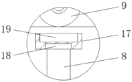
fig. 3 is an enlarged schematic view of a portion a in fig. 1 according to the present invention.
In the figure: 1. a box body; 2. a first electric telescopic rod; 3. a first pinch roller; 4. a guide wheel; 5. a roller; 6. an air outlet pipe; 7. an opening; 8. a strut; 9. a second pinch roller; 10. a second electric telescopic rod; 11. a fixing plate; 12. a spray head; 13. a hot air tank; 14. a heating block; 15. an air intake duct; 16. a fan; 17. a base plate; 18. a pressure sensor; 19. a humidity sensor.
Detailed Description
The technical solutions in the embodiments of the present invention will be described clearly and completely with reference to the accompanying drawings in the embodiments of the present invention, and it is obvious that the described embodiments are only some embodiments of the present invention, not all embodiments. Based on the embodiments in the present invention, all other embodiments obtained by a person skilled in the art without creative work belong to the protection scope of the present invention.
In the description of the present invention, it is to be noted that, unless otherwise explicitly specified or limited, the terms "mounted", "provided", "connected", and the like are to be construed broadly, such as "connected", which may be fixedly connected, detachably connected, or integrally connected; can be mechanically or electrically connected; they may be connected directly or indirectly through intervening media, or they may be interconnected between two elements. The specific meaning of the above terms in the present invention can be understood in specific cases to those skilled in the art.
The utility model discloses a box 1, first electric telescopic handle 2, first pinch roller 3, guide pulley 4, gyro wheel 5, outlet duct 6, opening 7, branch 8, second pinch roller 9, second electric telescopic handle 10, fixed plate 11, shower nozzle 12, hot gas case 13, heating block 14, breathing pipe 15, fan 16, bottom plate 17, pressure sensor 18 and 19 parts of humidity transducer are the parts that general standard or technical personnel in the field know, its structure and principle all are that this technical personnel all can learn through the technical manual or learn through conventional experimental method.
Referring to fig. 1-3, a textile dryer comprises a box body 1, wherein the middle ends of the left side and the right side of the box body 1 are respectively provided with an opening 7, the upper end and the lower end of the inner cavity of the opening 7 are respectively provided with a guide wheel 4 in a rotating way, the left end of the top of the inner cavity of the box body 1 is fixedly provided with a first electric telescopic rod 2, the bottom of the first electric telescopic rod 2 is fixedly provided with a first pressing wheel 3, the bottom of the inner cavity of the box body 1 is fixedly provided with a roller 5 under the first pressing wheel 3, the middle ends of the upper side and the lower side of the inner cavity of the box body 1 are respectively fixedly connected with a spray head 12 through a connecting rod, the lower part of the right side of the box body 1 is fixedly connected with a support rod 8, the top of the support rod 8 is fixedly connected with a bottom plate 17, a pressure sensor 18 is embedded between the bottom of the, the bottom of a second electric telescopic rod 10 is fixedly provided with a second pinch roller 9, the number of guide wheels 4 is four, a bottom plate 17 is positioned under the second pinch roller 9, the back of the box body 1 is fixedly connected with a hot air box 13, the inner cavity of the hot air box 13 is fixedly provided with a heating block 14, the left side of the hot air box 13 is fixedly provided with a fan 16, cloth can enter the box body 1 from the left side and leave the box body 1 from the right side through an opening 7, when the cloth enters, the cloth is clamped by a first pinch roller 3 and a roller 5, so that moisture in the cloth is extruded out, the efficiency and the effect of the cloth during drying can be improved, the first electric telescopic rod 2 is used for driving the first pinch roller 3 to move, the cloth with different thicknesses can be conveniently extruded, hot air in the hot air box 13 can be sucked out and sprayed out by the spray nozzles 12 through the fan 16, the cloth is dried, the drying effect can be improved by using the two spray nozzles 12 to, when the cloth goes out from the right side, the second pressing wheel 9 and the bottom plate 17 are utilized to enable the cloth to slide on the surfaces of the second pressing wheel 9 and the bottom plate 17, the humidity sensor 19 can be utilized to detect the humidity of the cloth sliding on the bottom plate 17, when the humidity is too high, a worker can control the machine to rotate reversely so that the cloth returns to the box body 1 to be dried, the second electric telescopic rod 10 is utilized to drive the second pressing wheel 9 to move, the device is convenient to be applied to the cloth with various thicknesses, the problem that partial cloth still contains moisture and is inconvenient to use due to the fact that the humidity of the cloth cannot be detected after the cloth is dried by the existing drying device is solved, the air suction port of the fan 16 is fixedly connected with the air suction pipe 15, the other end of the air suction pipe 15 is fixedly connected with the top on the left side of the inner cavity of the hot air box 13, the air outlet pipe, the air vent has been seted up to the bottom on hot-air box 13 right side, and the aperture of air vent equals with the aperture of dust screen, and the left end fixed mounting on the positive surface of box 1 has the PLC controller, and the right-hand member fixed mounting on the positive surface of box 1 has the display.
When the drying device is used, cloth can enter the box body 1 from the left side and leave the box body 1 from the right side through the opening 7, the cloth is clamped by the first pressing wheel 3 and the roller 5 when entering the cloth, so that moisture in the cloth is extruded out, the efficiency and the effect of the cloth drying can be improved, the first electric telescopic rod 2 is used for driving the first pressing wheel 3 to move, the cloth with different thicknesses can be conveniently extruded, hot air in the hot air box 13 can be sucked out through the fan 16 and sprayed out through the spray heads 12, the cloth is dried, the drying effect can be improved by respectively drying from the upper side and the lower side through the two spray heads 12, when the cloth goes out from the right side, the cloth slides on the surfaces of the second pressing wheel 9 and the bottom plate 17 by using the second pressing wheel 9 and the bottom plate 17, the humidity of the cloth sliding on the bottom plate 17 can be detected by the humidity sensor 19, and when the humidity is too high, a worker can control the machine to, make the cloth get back to and dry in box 1, utilize second electric telescopic handle 10 to drive second pinch roller 9 and remove, make things convenient for this device to be applicable to the cloth of various different thickness, solved present drying device and can not detect the humidity of cloth after drying the cloth, lead to still containing moisture in the partial cloth, the problem of the people's use of being not convenient for.
Although embodiments of the present invention have been shown and described, it will be appreciated by those skilled in the art that changes, modifications, substitutions and alterations can be made in these embodiments without departing from the principles and spirit of the invention, the scope of which is defined in the appended claims and their equivalents.
Claims (5)
1. The utility model provides a textile drying machine, includes box (1), its characterized in that: the middle ends of the left side and the right side of the box body (1) are respectively provided with an opening (7), the upper end and the lower end of an inner cavity of the opening (7) are respectively rotatably provided with a guide wheel (4) through a rotating shaft, the left end of the top of the inner cavity of the box body (1) is fixedly provided with a first electric telescopic rod (2), the bottom of the inner cavity of the box body (1) is fixedly provided with a first pinch roller (3) and a roller (5) under the first pinch roller (3), the middle ends of the upper side and the lower side of the inner cavity of the box body (1) are respectively fixedly connected with a spray head (12) through a connecting rod, the lower part of the right side of the box body (1) is fixedly connected with a support rod (8), the top of the support rod (8) is fixedly connected with a bottom plate (17), a pressure sensor (18) is embedded between the bottom of the bottom plate (17) and the support, the utility model discloses a solar energy water heater, including box (1), upper portion fixedly connected with fixed plate (11) on box (1) right side, the bottom fixed mounting of fixed plate (11) has second electric telescopic handle (10), the bottom fixed mounting of second electric telescopic handle (10) has second pinch roller (9), the back fixedly connected with hot-air box (13) of box (1), the inner chamber fixed mounting of hot-air box (13) has heating block (14), the left side fixed mounting of hot-air box (13) has fan (16).
2. A textile dryer according to claim 1, wherein: the bottom on the right side of the hot air box (13) is provided with a vent hole, and the aperture of the vent hole is equal to that of the dust screen.
3. A textile dryer according to claim 1, wherein: the air suction port of the fan (16) is fixedly connected with an air suction pipe (15), the other end of the air suction pipe (15) is fixedly connected with the top of the left side of the inner cavity of the hot air box (13), an air outlet of the fan (16) is fixedly connected with an air outlet pipe (6), and the other end of the air outlet pipe (6) is fixedly connected with the spray head (12).
4. A textile dryer according to claim 1, wherein: the left end fixed mounting on the positive surface of box (1) has the PLC controller, the right-hand member fixed mounting on the positive surface of box (1) has the display.
5. A textile dryer according to claim 1, wherein: the number of the guide wheels (4) is four, and the bottom plate (17) is positioned under the second pressing wheel (9).
Priority Applications (1)
| Application Number | Priority Date | Filing Date | Title |
|---|---|---|---|
| CN201921244217.1U CN210399847U (en) | 2019-08-02 | 2019-08-02 | Textile drying machine |
Applications Claiming Priority (1)
| Application Number | Priority Date | Filing Date | Title |
|---|---|---|---|
| CN201921244217.1U CN210399847U (en) | 2019-08-02 | 2019-08-02 | Textile drying machine |
Publications (1)
| Publication Number | Publication Date |
|---|---|
| CN210399847U true CN210399847U (en) | 2020-04-24 |
Family
ID=70359077
Family Applications (1)
| Application Number | Title | Priority Date | Filing Date |
|---|---|---|---|
| CN201921244217.1U Expired - Fee Related CN210399847U (en) | 2019-08-02 | 2019-08-02 | Textile drying machine |
Country Status (1)
| Country | Link |
|---|---|
| CN (1) | CN210399847U (en) |
Cited By (5)
| Publication number | Priority date | Publication date | Assignee | Title |
|---|---|---|---|---|
| CN111676630A (en) * | 2020-06-05 | 2020-09-18 | 海宁王骏新材料有限公司 | Intelligent drying device that textile fabric used |
| CN112815636A (en) * | 2021-02-02 | 2021-05-18 | 山东莱威新材料有限公司 | Device and method for manufacturing high-performance fiber non-woven fabric |
| CN113028799A (en) * | 2021-04-22 | 2021-06-25 | 蔡法华 | Textile fabric drying device for spinning |
| CN114383401A (en) * | 2021-12-08 | 2022-04-22 | 泰州印染机械有限公司 | Heating device for drying machine |
| CN115540523A (en) * | 2022-09-07 | 2022-12-30 | 贵州晟世锦绣民族文化投资有限公司 | Drying device is used in metal fabric production with liquid function is scraped in extrusion |
-
2019
- 2019-08-02 CN CN201921244217.1U patent/CN210399847U/en not_active Expired - Fee Related
Cited By (5)
| Publication number | Priority date | Publication date | Assignee | Title |
|---|---|---|---|---|
| CN111676630A (en) * | 2020-06-05 | 2020-09-18 | 海宁王骏新材料有限公司 | Intelligent drying device that textile fabric used |
| CN112815636A (en) * | 2021-02-02 | 2021-05-18 | 山东莱威新材料有限公司 | Device and method for manufacturing high-performance fiber non-woven fabric |
| CN113028799A (en) * | 2021-04-22 | 2021-06-25 | 蔡法华 | Textile fabric drying device for spinning |
| CN114383401A (en) * | 2021-12-08 | 2022-04-22 | 泰州印染机械有限公司 | Heating device for drying machine |
| CN115540523A (en) * | 2022-09-07 | 2022-12-30 | 贵州晟世锦绣民族文化投资有限公司 | Drying device is used in metal fabric production with liquid function is scraped in extrusion |
Similar Documents
| Publication | Publication Date | Title |
|---|---|---|
| CN210399847U (en) | Textile drying machine | |
| CN211668112U (en) | Cloth drying device for tailoring | |
| CN213389260U (en) | Textile sizing equipment | |
| CN111486688A (en) | Drying equipment is used in weaving with high-efficient dust removal effect | |
| CN210773258U (en) | Even fabrics drying-machine dries | |
| CN211340026U (en) | Even drying equipment of cloth for weaving | |
| CN204987748U (en) | Weaving drying device of environmental protection | |
| CN208920789U (en) | Circulation drying device is used in a kind of production of Song Dynasty brocade fabric | |
| CN215405090U (en) | Drying and leveling device for processing polyester cloth | |
| CN215507580U (en) | Auxiliary heating's rubberizing device for textile processing | |
| CN217154847U (en) | Drying equipment for textile yarns | |
| CN211346076U (en) | Polyester-silk spinning drying device | |
| CN212747223U (en) | Drying and cleaning device for fiber cloth production | |
| CN213514872U (en) | Drying equipment for silk | |
| CN208717556U (en) | A kind of control fabric shrink equipment for dyeing and finishing | |
| CN209128739U (en) | A kind of textile spends floating hair device | |
| CN112573135A (en) | Decorating machine drying room with mesh belt deviation correcting device | |
| CN117230602B (en) | Garment materials printing and dyeing drying equipment | |
| CN216205000U (en) | Cloth drying device for textile processing | |
| CN214307921U (en) | Circulation drying equipment for packaging tape | |
| CN216738892U (en) | Quick drying device is used in printing and dyeing of textile fabric | |
| CN209443243U (en) | A kind of framing shaping machine | |
| CN212253533U (en) | Printing and dyeing drying equipment for textile processing | |
| CN210569748U (en) | Drying device for textile machinery | |
| CN211695757U (en) | Textile product drying device |
Legal Events
| Date | Code | Title | Description |
|---|---|---|---|
| GR01 | Patent grant | ||
| GR01 | Patent grant | ||
| CF01 | Termination of patent right due to non-payment of annual fee | ||
| CF01 | Termination of patent right due to non-payment of annual fee |
Granted publication date: 20200424 Termination date: 20210802 |