Plastic injection mold with interrupted internal threads on inner wall
Technical Field
The utility model belongs to the technical field of the mould shaping, concretely relates to plastics injection mold of intermittent internal thread of inner wall area.
Background
The screw thread on the plastic part is divided into an internal screw thread and an external screw thread. Generally, the internal thread of a plastic part is formed by a threaded core, and the mold structure of the threaded part is different due to the particularity of the thread, and the way of releasing the thread is different. The case of the female screw is generally divided into a full thread and an interrupted thread according to the shape of the female screw, and the small-sized thread is substantially a full thread, while the larger-sized thread is substantially an interrupted thread. Interrupted threads are used because thread strengths above the 40mm dimension substantially exceed the strength required. The mode of the rotation moment of torsion that the product drawing of patterns of full thread needs is demolded, and the rotation moment of torsion that needs when the drawing of patterns is very big if the bigger full thread of size, very inconvenient, and the drawing of patterns degree of difficulty is big moreover, also is a damage to the mould if the moment of torsion is too big, has reduced the life of mould.
Disclosure of Invention
The utility model aims at providing an interior wall area intermittent internal thread's plastics injection mold adopts intermittent screw thread molding to the plastics internal thread of large size, solves the defect that the full thread drawing of patterns exists among the prior art.
The utility model discloses a plastics injection mold of intermittent internal thread in interior wall area that realizes through following mode, fixed die plate and movable mould board including the switching combination, fixed die plate upper end fix in proper order and take off runner plate and cover half seat, the runner cover is installed in cover half seat center department, the movable mould board lower extreme pass through the screw post and be connected with the movable mould seat, be located and be provided with roof and ejecting fixed plate between movable mould board and the movable mould seat, the roof is fixed on ejecting fixed plate, the lower extreme of ejector pin is fixed on ejecting fixed plate. A fixed die insert is arranged in the fixed die plate, the fixed die insert is fixedly connected with an inner drawing fixed die locking block through a bolt, and the fixed die insert is also provided with an upper half part of a cavity; a movable die insert is arranged in the movable die plate, a movable die core is sleeved and fixed on the outer side of the movable die insert, an inner drawing sliding block is arranged on the movable die core through a pressing block, and one end of the inner drawing sliding block is in contact with the inner wall of the movable die plate through a spring; the upper end of the ejector rod penetrates through the movable template and the movable die insert to be fixedly connected with the ejector block. The space between the pressing block and the inner drawing slide block and the space between the movable mould core and the top block form the lower half part of the mould cavity, and a complete mould cavity is formed after the fixed mould plate and the movable mould plate are closed.
The cross section of the further movable mould insert is convex, so a groove can be formed between the movable mould insert and the movable mould core, and the top block is placed in the groove.
The cross section of the further movable mould core is in a step shape, and the movable mould core is divided into a first step surface and a second step surface from bottom to top. The internal drawing sliding block is installed on the first step surface and can slide on the first step surface through the acting force of the spring, the upper end of the internal drawing sliding block and the second step surface of the movable mold core form a groove, and when the fixed mold plate and the movable mold plate are closed, the lower part of the internal drawing fixed mold locking block is inserted into the groove in a splicing mode.
The further inward-drawing sliding block is L-shaped.
The lower extreme of interior extraction mould locking piece have the groove, interior extraction slider upper end have the groove, so the groove of interior extraction mould locking piece forms to carve to be connected with the groove on the interior slider of taking out to one side, when the fixed die plate is closed with the movable mould board, interior extraction mould locking piece is carved to one side and is connected and outwards push the interior slider of taking out and carry out the product of moulding plastics after a certain position, when the fixed die plate separates with the movable mould board, under the effect of spring, the interior slider of taking out is inwards pushed, gives out the space for the discontinuous screw thread after the shaping and carries out the drawing of patterns.
The beneficial effects of the utility model are that take out slider drawing of patterns mode in adopting, when the drawing of patterns, take out the slider in, under the effect of spring, its direction of motion is inside to be slided, gives disconnected continuous screw thread and lets out the space drawing of patterns, has reduced the hindrance to disconnected screw thread. The ejector block is matched to fast and conveniently demould the product, so that damage to the mould due to overlarge torque is avoided, and the service life of the mould is shortened. The mold is reasonable in design, and the size of the mold is reduced, so that the mold is more convenient to use and carry.
Drawings
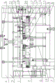
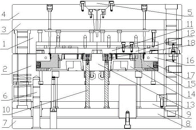
FIG. 1 is an overall structural view;
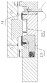
FIG. 2 is an enlarged view of a portion of the mold closed;
FIG. 3 is an enlarged view of a portion of the mold when open;
FIG. 4 is an enlarged schematic view of the mold after it is fully opened;
FIG. 5 is a view showing the structure of a product;
as shown in fig. 1 to 5, the fixed die plate (1), the movable die plate (2), the runner removing plate (3), the fixed die base (4), the sprue bush (5), the screw column (6), the movable die base (7), the top plate (8), the ejection fixing plate (9), the ejector rod (10), the fixed die insert (11), the internal extraction fixed die lock block (12), the movable die insert (13), the movable die core (14), the internal extraction slide block (15), the pressing block (16), the spring (17), the top block (18), the first step surface (19) and the second step surface (20).
Detailed Description
The utility model provides an interior wall area intermittent internal thread's plastics injection mold, including fixed die plate (1) and movable mould board (2) of switching combination, fixed die plate (1) upper end be fixed in proper order take off runner plate (3) and fixed die holder (4), install in fixed die holder (4) center department in runner cover (5), movable mould board (2) lower extreme pass through screw post (6) and be connected with movable die holder (7), be located and be provided with roof (8) and ejecting fixed plate (9) between movable mould board (2) and movable die holder (7), the lower extreme of ejector pin (10) is fixed on ejecting fixed plate (9). A fixed die insert (11) is arranged in the fixed die plate (1), and the fixed die insert (11) is fixedly connected with an internal drawing fixed die lock block (12) through a bolt; a movable die insert (13) is arranged in the movable die plate (2), a movable die core (14) is sleeved and fixed on the outer side of the movable die insert (13), an inner drawing sliding block (15) is installed on the movable die core (14) through a pressing block (16), and one end of the inner drawing sliding block (15) is in contact with the inner wall of the movable die plate (2) through a spring (17); the upper end of the ejector rod (10) penetrates through the movable template (2) and the movable die insert (13) to be fixedly connected with the ejector block (18).
Preferably, the movable die insert (13) is convex in cross section, and a groove in which the top block (18) is placed can be formed between the movable die insert (13) and the movable die core (14).
The further inward drawing slide block (15) is L-shaped.
The cross section of the preferable movable mould core (14) is in a step shape, the internal drawing slide block (15) is arranged on the first step surface (19), and the upper end of the internal drawing slide block (15) and the second step surface (20) of the movable mould core (14) form a groove.
The lower end of the further inner drawing fixed mold locking block (12) is provided with a groove.
The upper end of the further inner drawing slide block (15) is provided with a groove.
Firstly, a fixed die plate (1) and a movable die plate (2) are closed and fastened together through bolts, at the moment, the lower half part of an inner drawing fixed die locking block (12) is embedded into a groove formed by the upper end of an inner drawing sliding block (15) and a second step surface (20) of a movable die core (14), and the inner drawing fixed die locking block (12) pushes the inner drawing sliding block (15) outwards to a specified position through wedge connection. A complete cavity is formed by a cavity in the upper half part of the fixed die insert (11) and a cavity in the lower half part formed by all parts in the movable die plate (2), plastic materials are injected through the sprue bush (5), and the plastic materials flow into the cavity through an injection flow channel of the sprue bush (5) to be molded. After molding, the bolts are opened to slowly separate the fixed die plate (1) from the movable die plate (2), the internal drawing fixed die locking block (12) is separated from the groove, and the internal drawing sliding block (15) moves at the center of the die through the acting force of the spring (17) until the internal drawing sliding block touches the movable die core (14) and stops. At the moment, the interrupted thread is completely separated from the internal drawing slide block (15), then the ejection mechanism pushes the ejection block (18) to completely push the formed product out of the cavity, and the product is taken out of the mold and then is subjected to mold closing operation.