CN210336140U - Far-infrared pastes production with deciding device - Google Patents
Far-infrared pastes production with deciding device Download PDFInfo
- Publication number
- CN210336140U CN210336140U CN201921325529.5U CN201921325529U CN210336140U CN 210336140 U CN210336140 U CN 210336140U CN 201921325529 U CN201921325529 U CN 201921325529U CN 210336140 U CN210336140 U CN 210336140U
- Authority
- CN
- China
- Prior art keywords
- fixedly connected
- far infrared
- groove
- sliding
- cutting
- Prior art date
- Legal status (The legal status is an assumption and is not a legal conclusion. Google has not performed a legal analysis and makes no representation as to the accuracy of the status listed.)
- Expired - Fee Related
Links
- 238000004519 manufacturing process Methods 0.000 title claims abstract description 11
- 230000006835 compression Effects 0.000 claims description 8
- 238000007906 compression Methods 0.000 claims description 8
- 230000000712 assembly Effects 0.000 claims description 2
- 238000000429 assembly Methods 0.000 claims description 2
- 230000000694 effects Effects 0.000 abstract description 7
- 206010050296 Intervertebral disc protrusion Diseases 0.000 description 1
- 208000028571 Occupational disease Diseases 0.000 description 1
- 206010034464 Periarthritis Diseases 0.000 description 1
- 206010041591 Spinal osteoarthritis Diseases 0.000 description 1
- 208000036319 cervical spondylosis Diseases 0.000 description 1
- 201000010099 disease Diseases 0.000 description 1
- 208000037265 diseases, disorders, signs and symptoms Diseases 0.000 description 1
- 238000000034 method Methods 0.000 description 1
- 238000012986 modification Methods 0.000 description 1
- 230000004048 modification Effects 0.000 description 1
- 239000011505 plaster Substances 0.000 description 1
- 208000005801 spondylosis Diseases 0.000 description 1
- 238000002560 therapeutic procedure Methods 0.000 description 1
Images
Landscapes
- Radiation-Therapy Devices (AREA)
Abstract
The utility model discloses a far infrared pastes production with deciding device relates to far infrared pastes production field, including the workstation, the equal first motor of fixedly connected with in both sides of workstation, the one end fixedly connected with lead screw of first motor, the surperficial swing joint of lead screw has the slide bar, the top fixedly connected with clamping components of slide bar, the blade is tailor to the middle swing joint of workstation, the spout has been seted up to the middle inside of workstation, the groove of tailorring has been seted up to one side of spout, the one end fixedly connected with sliding block of tailorring the blade, the equal fixedly connected with catch bar in both sides of sliding block. The utility model discloses a first motor can drive the slide bar on the lead screw and remove, is convenient for adjust the distance between two clamping components, can paste the far infrared of different width and tailor, and the second motor can drive the second fixed block and have the effect that reciprocates, makes clamping component have the effect of fixed far infrared subsides, the effectual work efficiency who tailors that improves far infrared subsides.
Description
Technical Field
The utility model relates to a far infrared pastes production field, in particular to far infrared pastes production with deciding device.
Background
In recent years, people are often in a sub-health state due to the influence of factors such as work, families, environment and the like, occupational diseases such as cervical spondylosis, scapulohumeral periarthritis, lumbar disc herniation and the like seriously affect normal work and life of people, and people are used to plaster therapy for discomfort of diseases.
At present, the far infrared pastes and need decide far infrared subsides in process of production, but the device is decided to current far infrared subsides efficiency is lower, can reduce the output that far infrared pasted, consequently, proposes far infrared production with deciding the device and solve above-mentioned problem very necessity.
SUMMERY OF THE UTILITY MODEL
An object of the utility model is to provide a far infrared pastes production with deciding device to solve the lower problem of device efficiency is decided to far infrared subsides that provide among the above-mentioned background art.
In order to achieve the above object, the utility model provides a following technical scheme: a cutting device for far infrared paste production comprises a workbench, wherein two sides of the workbench are fixedly connected with first motors, one ends of the first motors are fixedly connected with lead screws, the surfaces of the lead screws are movably connected with sliding rods, the top ends of the sliding rods are fixedly connected with clamping assemblies, and the middle of the workbench is movably connected with a cutting blade;
a sliding groove is formed in the middle of the workbench, a cutting groove is formed in one side of the sliding groove, one end of the cutting blade is fixedly connected with a sliding block, and two sides of the sliding block are fixedly connected with pushing rods;
the clamping component comprises a first fixing block and a second fixing block, wherein the bottom end of the first fixing block is fixedly connected with a second motor, one end of the second motor is fixedly connected with a screw rod, one end of the screw rod is fixedly connected with a limiting plate, and a limiting groove is formed in the bottom of the second fixing block.
Optionally, one end fixedly connected with compression spring of spout, compression spring's one end and sliding block fixed connection.
Optionally, notches are formed in two sides of the top of the workbench, and the sliding rod is located in the notches and movably connected with the notches.
Optionally, the limiting plate is a threaded plate, the limiting groove is a threaded groove, and the limiting plate is located in the limiting groove and is in threaded connection with the limiting groove;
the first fixed block and the second fixed block are movably connected.
Optionally, the sliding block is located in the sliding groove and movably connected with the sliding groove;
the cutting blade is positioned in the cutting groove and is movably connected with the cutting groove.
Optionally, the number of the first motors is four, the four first motors are symmetrically arranged on two sides of the workbench, and the number of the first motors is equal to that of the sliding rods.
Optionally, a threaded hole is formed in the bottom end of the sliding rod, and the lead screw is located in the threaded hole and in threaded connection with the bottom end of the sliding rod.
The utility model discloses a technological effect and advantage:
1. the utility model discloses a first motor can drive the slide bar on the lead screw and remove, is convenient for adjust the distance between two clamping components, can cut out the far infrared subsides of different width, can drive the second fixed block through the second motor and have the effect that reciprocates, makes first fixed block and second fixed block fix the far infrared subsides to make clamping component have the effect of fixed far infrared subsides, the effectual work efficiency of cutting out that improves the far infrared subsides.
2. The utility model discloses a sliding block can be fixed cutting blade, can drive cutting blade on the sliding block through the catch bar and cut out far infrared subsides, and the cooperation of limiting plate and spacing groove can prevent to separate between first fixed block and the second fixed block.
Drawings
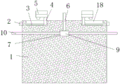
Fig. 1 is a schematic sectional view of the structure of the present invention.
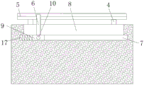
Fig. 2 is a schematic side view and sectional view of the structure of the present invention.
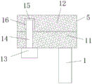
Fig. 3 is a schematic sectional view of the clamping assembly structure of the present invention.
In the figure: 1. a work table; 2. a first motor; 3. a lead screw; 4. a slide bar; 5. a clamping assembly; 6. cutting a blade; 7. a chute; 8. cutting a groove; 9. a slider; 10. a push rod; 11. a first fixed block; 12. a second fixed block; 13. a second motor; 14. a screw; 15. a limiting plate; 16. a limiting groove; 17. a compression spring; 18. a notch.
Detailed Description
The technical solutions in the embodiments of the present invention will be described clearly and completely with reference to the accompanying drawings in the embodiments of the present invention, and it is obvious that the described embodiments are only some embodiments of the present invention, not all embodiments. Based on the embodiments in the present invention, all other embodiments obtained by a person skilled in the art without creative work belong to the protection scope of the present invention.
In the description of the present invention, it is to be understood that the terms "center", "longitudinal", "lateral", "length", "width", "thickness", "upper", "lower", "front", "rear", "left", "right", "vertical", "horizontal", "top", "bottom", "inner", "outer", "clockwise", "counterclockwise", "axial", "radial", "circumferential", and the like, indicate the orientation or positional relationship indicated based on the drawings, and are only for convenience of description and simplicity of description, and do not indicate or imply that the device or element referred to must have a particular orientation, be constructed and operated in a particular orientation, and therefore, should not be construed as limiting the present invention.
In the present invention, unless otherwise expressly stated or limited, the terms "disposed," "mounted," "connected," and "fixed" are to be construed broadly, e.g., as meaning either a fixed connection or a removable connection; may be a mechanical connection; may be directly connected or indirectly connected through an intermediate. The specific meaning of the above terms in the present invention can be understood according to specific situations by those skilled in the art.
Furthermore, the terms "first", "second" and "first" are used for descriptive purposes only and are not to be construed as indicating or implying relative importance or implicitly indicating the number of technical features indicated. Thus, a feature defined as "first" or "second" may explicitly or implicitly include one or more of that feature.
The utility model provides a cutting device for producing far infrared paste as shown in figures 1-3, which comprises a workbench 1, wherein both sides of the top of the workbench 1 are provided with notches 18, sliding rods 4 are positioned in the notches 18 and movably connected with the notches 18, the notches 18 can facilitate the movement of the sliding rods 4, both sides of the workbench 1 are fixedly connected with first motors 2, the first motors 2 can drive the sliding rods 4 on a lead screw 3 to move, so as to adjust the distance between two clamping components 5 and cut the far infrared paste with different widths, the number of the first motors 2 is four, the four first motors 2 are symmetrically arranged on both sides of the workbench 1, the number of the first motors 2 is equal to that of the sliding rods 4, one end of the first motor 2 is fixedly connected with the lead screw 3, the surface of the lead screw 3 is movably connected with the sliding rods 4, the bottom end of the sliding rods 4 is provided with threaded holes, the lead screw 3 is positioned in the threaded hole and is in threaded connection with the bottom end of the sliding rod 4, the top end of the sliding rod 4 is fixedly connected with a clamping component 5, the middle of the workbench 1 is movably connected with a cutting blade 6, the middle inside of the workbench 1 is provided with a sliding groove 7, one end of the sliding groove 7 is fixedly connected with a compression spring 17, one end of the compression spring 17 is fixedly connected with a sliding block 9, the compression spring 17 can automatically reset after the sliding block 9 moves, one side of the sliding groove 7 is provided with a cutting groove 8, the cutting blade 6 is positioned in the cutting groove 8 and is movably connected with the cutting groove 8, one end of the cutting blade 6 is fixedly connected with the sliding block 9, the sliding block 9 can fix the cutting blade 6, the sliding block 9 is positioned in the sliding groove 7 and is movably connected with the sliding groove 7, both sides of the sliding block 9 are fixedly connected with push rods 10, the push rods 10 can, the clamping assembly 5 comprises a first fixing block 11 and a second fixing block 12, the first fixing block 11 is movably connected with the second fixing block 12, both sides of one end of the bottom of the first fixing block 11 are fixedly connected with a second motor 13, the second motor 13 can drive the second fixing block 12 to have the effect of moving up and down, so that the first fixing block 11 and the second fixing block 12 fix the far infrared patches, thereby make clamping unit 5 have the effect of fixed far-infrared subsides, the one end fixedly connected with screw rod 14 of second motor 13, the one end fixedly connected with limiting plate 15 of screw rod 14, limiting plate 15 is the thread plate, limiting groove 16 is the thread groove, limiting plate 15 is located limiting groove 16 and with limiting groove 16 threaded connection, the cooperation of limiting plate 15 and limiting groove 16 can prevent to separate between first fixed block 11 and the second fixed block 12, limiting groove 16 has been seted up to the bottom of second fixed block 12.
This practical theory of operation:
earlier drive slide bar 4 on the lead screw 3 through first motor 2 and remove, slide bar 4 drives clamping component 5 and removes, adjust the distance between two clamping component 5, make things convenient for the far infrared subsides of different width to tailor, then place the far infrared subsides between first fixed block 11 and the second fixed block 12, start second motor 13 afterwards, second motor 13 makes second fixed block 12 remove through limiting plate 15, make second fixed block 12 fix the far infrared subsides, at last through removing catch bar 10, catch bar 10 drives blade 6 on the sliding block 9 and tailors the far infrared subsides, thereby the effectual work efficiency who tailors that improves the far infrared subsides.
Finally, it should be noted that: although the present invention has been described in detail with reference to the foregoing embodiments, it will be apparent to those skilled in the art that modifications and variations can be made in the embodiments or in part of the technical features of the embodiments without departing from the spirit and the scope of the invention.
Claims (7)
1. The utility model provides a device is decided with deciding to far infrared production, includes workstation (1), its characterized in that: the cutting machine is characterized in that both sides of the workbench (1) are fixedly connected with first motors (2), one ends of the first motors (2) are fixedly connected with lead screws (3), the surfaces of the lead screws (3) are movably connected with sliding rods (4), the top ends of the sliding rods (4) are fixedly connected with clamping assemblies (5), and the middle of the workbench (1) is movably connected with cutting blades (6);
a sliding groove (7) is formed in the middle of the workbench (1), a cutting groove (8) is formed in one side of the sliding groove (7), one end of the cutting blade (6) is fixedly connected with a sliding block (9), and two sides of the sliding block (9) are fixedly connected with pushing rods (10);
the clamping component (5) comprises a first fixing block (11) and a second fixing block (12), wherein the bottom end of the first fixing block (11) is fixedly connected with a second motor (13) at two sides, one end of the second motor (13) is fixedly connected with a screw rod (14), one end of the screw rod (14) is fixedly connected with a limiting plate (15), and a limiting groove (16) is formed in the bottom of the second fixing block (12).
2. The cutting device for producing the far infrared paste according to claim 1, characterized in that:
one end fixedly connected with compression spring (17) of spout (7), the one end and sliding block (9) fixed connection of compression spring (17).
3. The cutting device for producing the far infrared paste according to claim 1, characterized in that:
notch (18) have all been seted up to the top both sides of workstation (1), slide bar (4) are located notch (18) and with notch (18) swing joint.
4. The cutting device for producing the far infrared paste according to claim 1, characterized in that:
the limiting plate (15) is a threaded plate, the limiting groove (16) is a threaded groove, and the limiting plate (15) is positioned in the limiting groove (16) and is in threaded connection with the limiting groove (16);
the first fixed block (11) is movably connected with the second fixed block (12).
5. The cutting device for producing the far infrared paste according to claim 1, characterized in that:
the sliding block (9) is positioned in the sliding groove (7) and is movably connected with the sliding groove (7);
the cutting blade (6) is positioned in the cutting groove (8) and is movably connected with the cutting groove (8).
6. The cutting device for producing the far infrared paste according to claim 1, characterized in that:
the number of the first motors (2) is four, the four first motors (2) are symmetrically arranged on two sides of the workbench (1), and the number of the first motors (2) is equal to that of the sliding rods (4).
7. The cutting device for producing the far infrared paste according to claim 1, characterized in that:
the bottom end of the sliding rod (4) is provided with a threaded hole, and the lead screw (3) is positioned in the threaded hole and is in threaded connection with the bottom end of the sliding rod (4).
Priority Applications (1)
| Application Number | Priority Date | Filing Date | Title |
|---|---|---|---|
| CN201921325529.5U CN210336140U (en) | 2019-08-15 | 2019-08-15 | Far-infrared pastes production with deciding device |
Applications Claiming Priority (1)
| Application Number | Priority Date | Filing Date | Title |
|---|---|---|---|
| CN201921325529.5U CN210336140U (en) | 2019-08-15 | 2019-08-15 | Far-infrared pastes production with deciding device |
Publications (1)
| Publication Number | Publication Date |
|---|---|
| CN210336140U true CN210336140U (en) | 2020-04-17 |
Family
ID=70175063
Family Applications (1)
| Application Number | Title | Priority Date | Filing Date |
|---|---|---|---|
| CN201921325529.5U Expired - Fee Related CN210336140U (en) | 2019-08-15 | 2019-08-15 | Far-infrared pastes production with deciding device |
Country Status (1)
| Country | Link |
|---|---|
| CN (1) | CN210336140U (en) |
-
2019
- 2019-08-15 CN CN201921325529.5U patent/CN210336140U/en not_active Expired - Fee Related
Similar Documents
| Publication | Publication Date | Title |
|---|---|---|
| CN210394948U (en) | Cutting device for textile processing | |
| CN212312124U (en) | Slicing device for processing traditional Chinese medicine decoction pieces | |
| CN208913230U (en) | A kind of pole piece trimming device | |
| CN209349354U (en) | SMT Inductor exit foot cut device | |
| CN212635959U (en) | Edge cutting device for thin film processing | |
| CN211590221U (en) | Precision cutting mechanism and carrier band receiving device | |
| CN205058091U (en) | Soap cutting device | |
| CN209792759U (en) | Aluminum product cutting machine with automatic chip collecting function | |
| CN220826400U (en) | Flattening device is used in cloth processing | |
| CN213306279U (en) | Brush cutter aircraft nose connection structure | |
| CN211161546U (en) | Mould adjusting device of hardware stamping mould | |
| CN210453288U (en) | Mica that easily cuts is with section device | |
| CN211073835U (en) | Axial adjusting device for circular knife of die-cutting machine | |
| CN209849997U (en) | Clipping machine structure of automobile embossing production line | |
| CN210325554U (en) | Manual forming machine for capacitor | |
| CN216028590U (en) | Linear cutting machine tool for processing aluminum profile extrusion die | |
| CN208674769U (en) | A kind of Novel wire-stripping machine | |
| CN215600501U (en) | Lithium ion battery diaphragm hot cutting device | |
| CN221848778U (en) | A precise positioning structure of a hydraulic shearing machine | |
| CN207495727U (en) | A kind of Contiuum type ceramics stepped plate extrusion die | |
| CN223265832U (en) | A knife with replaceable blade | |
| CN221389199U (en) | A cutting device for aluminum rod processing that is easy to disassemble | |
| CN216299427U (en) | Cutting device for rubber processing | |
| CN210524017U (en) | Cutting milling machine is used in auto-parts processing | |
| CN218748090U (en) | Forming device of high-performance heat conducting fin |
Legal Events
| Date | Code | Title | Description |
|---|---|---|---|
| GR01 | Patent grant | ||
| GR01 | Patent grant | ||
| CF01 | Termination of patent right due to non-payment of annual fee |
Granted publication date: 20200417 Termination date: 20210815 |
|
| CF01 | Termination of patent right due to non-payment of annual fee |