Fried egg feeding device
Technical Field
The utility model relates to a fried egg technical field, more specifically say, relate to a fried egg feeding device.
Background
Egg food is rich in protein and has various practices, among which scrambled eggs are a relatively delicious method of consumption. When a large amount of egg frying processing is carried out, the egg liquid is generally directly added into the frying pan manually, if a large amount of egg liquid is added at one time, the frying is difficult, the frying pan is easy to be burnt, if the egg liquid is slowly added, too much manpower is wasted, and the egg frying quality is influenced because the egg liquid cannot be uniformly added during feeding.
SUMMERY OF THE UTILITY MODEL
To overcome the defects, the utility model provides a fried egg feeding device.
In order to achieve the above purpose, the utility model adopts the following technical scheme:
a fried egg feeding device comprises a fixed box body, wherein a containing hole is formed in the upper end of the fixed box body, a heating table is mounted on the inner lower surface of the fixed box body, a fried dish pot is arranged above the heating table, a circular supporting plate is mounted on the outer side of the upper end of the fried dish pot, a circular supporting plate is arranged on the lower surface of the circular supporting plate and is arranged at the upper end of the fixed box body, a servo motor is mounted on one side of the upper surface of the fixed box body, a rotating plate is mounted at the rotating end of the servo motor, a supporting rod is mounted on one side of the upper surface of the rotating plate, an egg liquid spray head inclining downwards is mounted on one side of the upper end of the supporting rod, a containing plate is mounted on the front side of the upper surface of the rotating plate, a conical through hole is formed in the front side of the containing plate, an iron ring is arranged at the lower end of the egg liquid bearing bowl, and the egg liquid bearing bowl is placed below the outlet end of the egg liquid spray head.
Further, the stirring device comprises a stirring mechanism, wherein the stirring mechanism comprises an F-shaped containing frame, a rotating motor, a driving wheel, a driving belt, a through hole, fixing holes, a connecting column, a connecting hole, a rotating shaft, a rotating table and a shovel, the F-shaped containing frame is fixedly arranged on one side of the upper surface of a circular supporting plate, two fixing holes are formed in two sides of the upper end in the F-shaped containing frame, the through hole is formed below the fixing hole, the rotating motor is positioned below the through hole on the inner side, a plurality of connecting holes are formed above the rotating motor, the lower end of the connecting column penetrates through the connecting hole and is fixedly connected with the upper end of the rotating motor, the upper end of the rotating motor penetrates through the through hole and extends into the fixing hole, the upper end of the rotating shaft is inserted into the fixing hole on the outer side, the lower end of, the shovel is provided with four shovels, the four shovels are uniformly distributed and installed on the lower surface of the rotating table, the number of the driving wheels is two, the two driving wheels are fixedly installed on the rotating end and the rotating shaft of the rotating motor respectively, and the driving belt is sleeved on the outer sides of the two driving wheels.
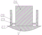
Further, still include unloading mechanism, unloading mechanism includes rotating support frame, round pin axle, fixed plate, round hole, upset support frame, rotating support frame upper end fixed mounting is in frying pan upper end one side, the round pin axle is installed to rotating support frame both sides surface lower extreme, the fixed plate is equipped with two, the fixed plate is installed at fixed box upper surface, the fixed plate is located the rotating support frame both sides, the round hole is equipped with two, the round hole is located the fixed plate respectively, round pin axle one end and rotating support frame side surface fixed connection, the round pin axle other end stretches into in the round hole, upset support frame is equipped with two, upset support frame one side and frying pan upper end fixed connection.
Furthermore, the section of the fixed box body is in a convex shape, and the protruding part of the upper end of the fixed box body inclines inwards.
Furthermore, a support column is arranged on the inner side of the lower end of the F-shaped containing frame.
The utility model has the advantages that: mix egg liquid earlier in the blending tank, when carrying out the fried egg, can be by external pump with egg liquid through even spraying of egg liquid shower nozzle in the fried dish pot, need not the manual work and add to the shower nozzle can rotate, conveniently directly overturns the finished product and pours out, is equipped with egg liquid and accepts the bowl, can catch remaining egg liquid when not adding the raw materials, reduces extravagantly.
Drawings
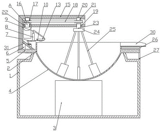
Fig. 1 is a schematic structural view of a fried egg feeding device according to the present invention;
FIG. 2 is an enlarged view of a portion of FIG. 1A;
FIG. 3 is a schematic view showing the connection between the holding plate and the egg liquid receiving bowl;
fig. 4 is a schematic top view of the egg feeding device according to the present invention;
FIG. 5 is a partial schematic view of the blanking mechanism;
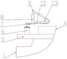
FIG. 6 is a schematic view of the egg liquid receiving bowl in position during frying of an egg;
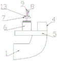
FIG. 7 is a schematic view of the egg liquid bowl in a position to collect the finished product after the frying of the egg;
in the figure, 1, a box body is fixed; 2. a containing hole; 3. a heating stage; 4. a frying pan; 5. a circular support plate; 6. a servo motor; 7. a rotating plate; 8. a support bar; 9. an egg liquid spray head; 10. a holding plate; 11. a tapered through hole; 12. an electromagnet; 13. an egg liquid receiving bowl; 14. an iron ring; 15. an F-shaped containing frame; 16. a rotating electric machine; 17. a driving wheel; 18. a drive belt; 19. a through hole; 20. a fixing hole; 21. connecting columns; 22. connecting holes; 23. a rotating shaft; 24. a rotating table; 25. a shovel; 26. rotating the support frame; 27. a pin shaft; 28. a fixing plate; 29. a circular hole; 30. turning over the support frame; 31. and (4) a support column.
Detailed Description
The invention will now be described in detail with reference to the drawings, as shown in figures 1-7.
In the embodiment, the egg frying and feeding device comprises a fixed box body 1, wherein the upper end of the fixed box body 1 is provided with a containing hole 2, the lower surface in the fixed box body 1 is provided with a heating table 3, a frying pan 4 is arranged above the heating table 3, the outer side of the upper end of the frying pan 4 is provided with a circular support plate 5, the lower surface of the circular support plate 5 is placed at the upper end of the fixed box body 1, one side of the upper surface of the fixed box body 1 is provided with a servo motor 6, the rotating end of the servo motor 6 is provided with a rotating plate 7, one side of the upper surface of the rotating plate 7 is provided with a support rod 8, one side of the upper end of the support rod 8 is provided with an egg liquid spray nozzle 9 inclined downwards, the front side of the upper surface of the rotating plate 7 is provided with a containing plate 10, the front side of the containing plate 10 is provided with a conical through hole 11, the lower surface of the rotating plate, an iron ring 14 is arranged at the lower end of the egg liquid receiving bowl 13, and the egg liquid receiving bowl 13 is arranged below the outlet end of the egg liquid spray head 9; the stirring device also comprises a stirring mechanism, the stirring mechanism comprises an F-shaped containing frame 15, a rotating motor 16, a transmission wheel 17, a transmission belt 18, a through hole 19, fixing holes 20, a connecting column 21, connecting holes 22, a rotating shaft 23, a rotating table 24 and a shovel 25, the F-shaped containing frame 15 is fixedly arranged on one side of the upper surface of the circular support plate 5, two fixing holes 20 are formed in two sides of the upper end in the F-shaped containing frame 15, the through hole 19 is formed below the fixing hole 20, the rotating motor 16 is positioned below the through hole 19 on the inner side, a plurality of connecting holes 22 are formed above the rotating motor 16, the lower end of the connecting column 21 penetrates through the connecting holes 22 to be fixedly connected with the upper end of the rotating motor 16, the upper end of the rotating motor 16 penetrates through the through hole 19 to extend into the fixing hole 20, the upper end of the rotating shaft 23 is inserted into the fixing hole 20 on the outer, four shovels 25 are arranged, the four shovels 25 are uniformly distributed and arranged on the lower surface of the rotating table 24, two transmission wheels 17 are arranged, the two transmission wheels are respectively and fixedly arranged on the rotating end of the rotating motor 16 and the rotating shaft 23, and the transmission belt 18 is sleeved on the outer sides of the two transmission wheels 17; the automatic feeding device is characterized by further comprising a feeding mechanism, the feeding mechanism comprises a rotary supporting frame 26, a pin shaft 27, a fixing plate 28, two round holes 29 and a turnover supporting frame 30, the upper end of the rotary supporting frame 26 is fixedly installed on one side of the upper end of the frying pan 4, the lower ends of the surfaces of the two sides of the rotary supporting frame 26 are provided with the pin shaft 27, the fixing plate 28 is installed on the upper surface of the fixed box body 1, the fixing plate 28 is located on the two sides of the rotary supporting frame 26, the two round holes 29 are respectively located on the fixing plate 28, one end of the pin shaft 27 is fixedly connected with the side surface of the rotary supporting frame 26, the other end of the pin shaft 27 extends into the round holes 29; the section of the fixed box body 1 is convex, and the protruding part of the upper end of the fixed box body inclines inwards; the inner side of the lower end of the F-shaped containing frame is provided with a supporting column.
The working principle of the embodiment is as follows: the device is controlled by an external controller, the power is switched on, mixed egg liquid is placed on one side of a fixed box body 1 in advance, an inlet end of an egg liquid spray head 9 is placed into a mixing barrel containing the egg liquid, a frying pan 4 is placed on a heating table 4 for heating when eggs are fried, a circular ring supporting plate 5 is placed on the upper end of the fixed box body 1 for supporting, the heating table 3 is started to heat the frying pan 4, a servo motor 6 is started to rotate for a certain angle, a rotating plate 7, an egg liquid receiving bowl 13 and an egg liquid spray head 9 are rotated to the upper side of one side of the frying pan 4, an electromagnet 12 is started in the rotating process, the electromagnet attracts a steel ring 14, the egg liquid receiving bowl 13 is prevented from falling, the vibration of the egg liquid receiving bowl 13 can be reduced, the egg liquid is prevented from spilling, after the frying pan 4 is heated to a certain degree, an external pump is started to spill the egg liquid in the mixing barrel into the frying pan 4 through the egg liquid spray head 9, meanwhile, the rotating motor 16 is started to rotate, the driving wheel 17 on the rotating end of the rotating motor 16 is driven to rotate by the rotating motor and is driven to rotate through the driving belt 18, the driving wheel 17 on the rotating shaft 23 is driven to rotate, so that the rotating shaft 23 and the rotating platform 24 rotate, a plurality of shovels 25 are driven to stir and fry egg liquid, after a certain amount of egg liquid is added into the frying pan 4, an external pump is closed, the residual egg liquid in the egg liquid spray head 9 falls into the egg liquid receiving bowl 13, waste is reduced, after frying is finished, the servo motor 6 is started to rotate reversely, the rotating plate 7, the egg liquid receiving bowl 13 and the egg liquid spray head 9 are rotated to the upper part of the outer side of the frying pan 4, the heating platform 3 is closed, the pin shaft 27 on the rotating support frame 26 is driven to rotate around the round hole 29 on the fixed plate 28 by pressing the overturning support frame 30, so that the frying pan 4 is overturned, and finished, and then the process is repeated to stir eggs, after the eggs are in operation for a period of time, the egg liquid receiving bowl 13 is gradually filled with the eggs, the electromagnet 12 is closed, the egg liquid receiving bowl 13 is taken down, the egg liquid in the egg liquid receiving bowl 13 is recovered, and the consumption is reduced.
Above-mentioned technical scheme has only embodied the utility model discloses technical scheme's preferred technical scheme, some changes that this technical field's technical personnel probably made to some parts wherein have all embodied the utility model discloses a principle belongs to within the protection scope of the utility model.