CN210326609U - Electrical equipment for road and bridge engineering construction - Google Patents
Electrical equipment for road and bridge engineering construction Download PDFInfo
- Publication number
- CN210326609U CN210326609U CN201921509844.3U CN201921509844U CN210326609U CN 210326609 U CN210326609 U CN 210326609U CN 201921509844 U CN201921509844 U CN 201921509844U CN 210326609 U CN210326609 U CN 210326609U
- Authority
- CN
- China
- Prior art keywords
- groove
- electric box
- rotating wheel
- road
- electric
- Prior art date
- Legal status (The legal status is an assumption and is not a legal conclusion. Google has not performed a legal analysis and makes no representation as to the accuracy of the status listed.)
- Expired - Fee Related
Links
- 238000010276 construction Methods 0.000 title claims abstract description 19
- 230000000149 penetrating effect Effects 0.000 claims abstract description 4
- 238000010586 diagram Methods 0.000 description 2
- 230000007547 defect Effects 0.000 description 1
- 238000000034 method Methods 0.000 description 1
- 238000012986 modification Methods 0.000 description 1
- 230000004048 modification Effects 0.000 description 1
- 238000006467 substitution reaction Methods 0.000 description 1
Images



Landscapes
- Motorcycle And Bicycle Frame (AREA)
Abstract
The electric appliance device for road and bridge engineering construction comprises an electric box, wherein a first groove is formed in the side surface of the electric box along the vertical direction, a guide rail is arranged in the first groove, a circular groove is formed in the side surface of a sliding block, a rotating shaft is arranged in the circular groove and is connected with a circular groove bearing, a second groove penetrating through the side surface of the rotating shaft is formed in one end of the rotating shaft, and a first rotating wheel is arranged in the second groove, so that the electric appliance device is suitable for the condition that a bridge floor cannot be well placed or the electric box needs to be carried frequently, an L-shaped supporting plate is hung through two second rotating wheels, the first rotating wheel is enabled to be rotated to the other cross beam of a railing at two sides of the bridge through moving the sliding block, the electric box is enabled to be close to the L-shaped supporting plate, only the electric box needs to be pushed, the equipment can be moved on the railing through the first rotating wheel and the second rotating wheel, need not to occupy the bridge floor area, it is convenient to remove, can be more convenient use in longer bridge floor restoration or construction work.
Description
Technical Field
The utility model belongs to the construction equipment field, specifically speaking are electric apparatus for road and bridge engineering construction.
Background
At present, the bridge construction and the work of maintaining of stage need be equipped with the electronic box, and when the bridge was longer, every removed a place just need carry the electronic box, and this process is loaded down with trivial details and hard, and when whole bridge floor all need be restoreed, the electronic box can't be placed on the bridge floor, just need connect the power supply demand that very long electric wire guaranteed work, and need run the operation electronic box back and forth, cause very big inconvenience.
SUMMERY OF THE UTILITY MODEL
The utility model provides an electric apparatus is used in road and bridge engineering construction for solve the defect among the prior art.
The utility model discloses a following technical scheme realizes:
the electric appliance device for road and bridge engineering construction comprises an electric box, wherein the side surface of the electric box is provided with a first groove along the vertical direction, a guide rail is arranged in the first groove, a slide block is arranged on the guide rail, the side surface of the slide block is provided with a circular groove, a rotating shaft is arranged in the circular groove and is connected with a circular groove bearing, one end of the rotating shaft is provided with a second groove penetrating through the side surface of the rotating shaft, a first rotating wheel is arranged in the second groove, the second groove is rotatably connected with the first rotating wheel, the side surface of the electric box is provided with an L-shaped support plate, one end of the L-shaped support plate is hinged with the top of the side surface of the electric box, the inner side of the L-shaped support plate is provided with a third groove, the third groove corresponds to the first groove, the first rotating wheel extends out of the first groove to the third groove, the inner corner of the L-shaped support plate is provided with two vertical fourth grooves, the, fifth grooves are formed in corners of the electric box, and the second rotating wheels stretch into the fifth grooves through the fourth grooves.
According to the electric appliance device for road and bridge engineering construction, the side face of the other end of the L-shaped support plate is provided with the sixth groove, the pin is arranged in the sixth groove, and one end of the pin is connected with the bottom of the sixth groove through the spring.
According to the electric appliance device for road and bridge engineering construction, the handle is installed at the center of the top of the electric box.
According to the electric appliance device for road and bridge engineering construction, the side surfaces of the first rotating wheel and the second rotating wheel are both in a concave arc shape.
The utility model has the advantages that: the utility model is suitable for a condition when the bridge floor can't place or need often carry the electronic box well, through opening L type extension board (as shown in fig. 2), place the second runner on the crossbeam of the railing on bridge both sides, hang L type extension board through two second runners, make first runner correspond to another crossbeam of the railing on bridge both sides through moving the slider on, make electronic box and L type extension board lean on tightly, only need promote the electronic box, can make equipment remove on the railing through first runner and second runner, if need fixed placement equipment, then it is rotatory with the pivot, make first runner be vertical state (as shown in fig. 3), support and lean on vertical railing, this equipment operation is simple, need not to occupy the bridge floor area, it is convenient to remove, can be more convenient use in longer bridge floor restoration or construction work.
Drawings
In order to more clearly illustrate the embodiments of the present invention or the technical solutions in the prior art, the drawings needed to be used in the description of the embodiments or the prior art will be briefly described below, and it is obvious that the drawings in the following description are some embodiments of the present invention, and for those skilled in the art, other drawings can be obtained according to these drawings without inventive labor.
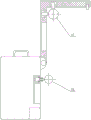
Fig. 1 is a schematic structural view of the present invention; fig. 2 is a first state diagram of use of the present utility model; FIG. 3 is a second state diagram of the present invention; fig. 4 is a partial enlarged view of fig. 1 at point i.
Detailed Description
In order to make the objects, technical solutions and advantages of the embodiments of the present invention clearer, the embodiments of the present invention will be clearly and completely described below with reference to the accompanying drawings in the embodiments of the present invention, and it is obvious that the described embodiments are some, but not all, embodiments of the present invention. Based on the embodiments in the present invention, all other embodiments obtained by a person skilled in the art without creative efforts belong to the protection scope of the present invention.
An electric appliance for road and bridge engineering construction is shown in the figure and comprises an electric box 1, wherein the side surface of the electric box 1 is provided with a first groove 2 along the vertical direction, a guide rail 3 is arranged in the first groove 2, a slide block 4 is arranged on the guide rail 3, the side surface of the slide block 4 is provided with a circular groove 5, a rotating shaft 6 is arranged in the circular groove 5, the rotating shaft 6 is connected with the circular groove 5 through a bearing, one end of the rotating shaft 6 is provided with a second groove 7 penetrating through the side surface of the rotating shaft, a first rotating wheel 8 is arranged in the second groove 7, the second groove 7 is rotatably connected with the first rotating wheel 8, the side surface of the electric box 1 is provided with an L-shaped support plate 9, one end of the L-shaped support plate 9 is hinged with the top of the side surface of the electric box 1, the inner side of the L-shaped support plate 9 is provided with a third groove 10, the third groove 10 corresponds to the first groove 2, the, the second rotating wheels 12 are installed in the fourth grooves 11, the second rotating wheels 12 are connected with the fourth grooves 11 in a rotating mode, the axes of the two second rotating wheels 12 are perpendicular to each other, the fifth grooves 13 are formed in the corners of the electronic box 1, and the second rotating wheels 12 extend into the fifth grooves 13 through the fourth grooves 11. The utility model is suitable for the situation that the bridge deck can not be placed well or the electric box needs to be carried frequently, the second rotating wheel 12 is placed on the cross beam 17 of the railing at the two sides of the bridge by opening the L-shaped support plate 9 (as shown in figure 2), the L-shaped support plate is hung through the two second rotating wheels 12, the first rotating wheel 8 is enabled to correspond to the other cross beam 18 of the railing at the two sides of the bridge through the movable sliding block 4, the electric box 1 and the L-shaped support plate 9 are enabled to be close, only the electric box needs to be pushed, the equipment can be enabled to move on the railing through the first rotating wheel 8 and the second rotating wheel 12, if fixed placement equipment is required, then the rotating shaft 6 is rotated, so that the first rotating wheel 8 is in a vertical state (as shown in fig. 3) and is supported on the vertical railing 19, the equipment is simple to operate, does not need to occupy the area of the bridge floor, is convenient to move, and can be used in longer bridge floor repair or construction work more conveniently.
Specifically, as shown in the figure, a sixth groove 15 is formed in the other end side surface of the L-shaped support plate 9 according to the embodiment, a pin 14 is installed in the sixth groove 15, and one end of the pin 14 is connected to the bottom of the sixth groove 15 through a spring. This design can guarantee to draw in electronic box 1 and L type extension board 9 in the time, put and prevent electronic box 1 and L type extension board 9 reciprocal hunting, when needing to open, only need press pin 14 down, upset L type extension board 9 just can, facilitate the use and transport.
Specifically, as shown in the figure, the handle 16 is installed at the center of the top of the electrical box 1 in the embodiment. This design can conveniently be carried and carry and take.
Further, as shown in the drawings, the side surfaces of the first runner 8 and the second runner 12 in the embodiment are both concave arc-shaped. This design can be better make first runner 8 and second runner 12 laminate mutually with the circular horizontal pole of railing department above the bridge, more stable when making the promotion electronic box.
Finally, it should be noted that: the above embodiments are only used to illustrate the technical solution of the present invention, and not to limit it; although the present invention has been described in detail with reference to the foregoing embodiments, it should be understood by those skilled in the art that: the technical solutions described in the foregoing embodiments may still be modified, or some technical features may be equivalently replaced; such modifications and substitutions do not depart from the spirit and scope of the present invention in its corresponding aspects.
Claims (4)
1. Electric apparatus is used in road and bridge engineering construction, its characterized in that: comprises an electric box (1), a first groove (2) is formed in the side surface of the electric box (1) along the up-down direction, a guide rail (3) is arranged in the first groove (2), a slide block (4) is arranged on the guide rail (3), a circular groove (5) is formed in the side surface of the slide block (4), a rotating shaft (6) is arranged in the circular groove (5), the rotating shaft (6) is in bearing connection with the circular groove (5), a second groove (7) penetrating through the side surface of the rotating shaft (6) is formed in one end of the rotating shaft (6), a first rotating wheel (8) is arranged in the second groove (7), the second groove (7) is in rotating connection with the first rotating wheel (8), an L-shaped support plate (9) is arranged on the side surface of the electric box (1), one end of the L-shaped support plate (9) is hinged with the top of the side surface of the electric box (1), a third groove (10) is formed in the inner side surface of the L-shaped support plate (9), the third groove (10) corresponds to the, two perpendicular fourth recesses (11) are seted up to inboard corner of L type extension board (9), and second runner (12) are all installed to fourth recess (11) the inside, and second runner (12) all rotate with fourth recess (11) and are connected, the axis mutually perpendicular of two second runners (12), fifth recess (13) are seted up to electronic box (1) corner, and second runner (12) all stretch into in fifth recess (13) through fourth recess (11).
2. The electric appliance device for road and bridge engineering construction according to claim 1, wherein: a sixth groove (15) is formed in the side face of the other end of the L-shaped support plate (9), a pin (14) is installed in the sixth groove (15), and one end of the pin (14) is connected with the bottom of the sixth groove (15) through a spring.
3. The electric appliance device for road and bridge engineering construction according to claim 1, wherein: the handle (16) is arranged at the center of the top of the electric box (1).
4. The electric appliance device for road and bridge engineering construction according to claim 1, wherein: the side surfaces of the first rotating wheel (8) and the second rotating wheel (12) are both in a concave arc shape.
Priority Applications (1)
| Application Number | Priority Date | Filing Date | Title |
|---|---|---|---|
| CN201921509844.3U CN210326609U (en) | 2019-09-11 | 2019-09-11 | Electrical equipment for road and bridge engineering construction |
Applications Claiming Priority (1)
| Application Number | Priority Date | Filing Date | Title |
|---|---|---|---|
| CN201921509844.3U CN210326609U (en) | 2019-09-11 | 2019-09-11 | Electrical equipment for road and bridge engineering construction |
Publications (1)
| Publication Number | Publication Date |
|---|---|
| CN210326609U true CN210326609U (en) | 2020-04-14 |
Family
ID=70132460
Family Applications (1)
| Application Number | Title | Priority Date | Filing Date |
|---|---|---|---|
| CN201921509844.3U Expired - Fee Related CN210326609U (en) | 2019-09-11 | 2019-09-11 | Electrical equipment for road and bridge engineering construction |
Country Status (1)
| Country | Link |
|---|---|
| CN (1) | CN210326609U (en) |
-
2019
- 2019-09-11 CN CN201921509844.3U patent/CN210326609U/en not_active Expired - Fee Related
Similar Documents
| Publication | Publication Date | Title |
|---|---|---|
| CN210101666U (en) | Transport trolley with better protective performance for performance props | |
| CN205016893U (en) | High voltage isolator overhauls platform | |
| CN210838594U (en) | A power box for power engineering | |
| CN207326340U (en) | A kind of automatic rotation location equipment of battery production | |
| CN209021607U (en) | A kind of integrally formed color steel machining wallboard equipment | |
| CN215614854U (en) | Dewaxing kettle with material part quick pushing function | |
| CN218064280U (en) | Measurement device for budget estimate BIM | |
| CN107761648B (en) | A kind of cleaning snow in winter device | |
| CN214147118U (en) | Balancing device for electromechanical equipment installation | |
| CN210763019U (en) | Conducting rod conveying device with conducting rod cleaning function | |
| CN210822351U (en) | Transmission device of mobile vehicle platform | |
| CN207571929U (en) | Parts fixing device for automobile teaching | |
| CN207345891U (en) | A kind of clothes closet mobile device | |
| CN208020164U (en) | A portable power maintenance box | |
| CN210898078U (en) | Portable switch board | |
| CN209872236U (en) | Freely-lifting type receiving pry | |
| CN215626526U (en) | Vapour is repaiied and is used portable jack-up shallow | |
| CN205741266U (en) | A kind of cleaning electroplates equipment integrating | |
| CN221835785U (en) | Glass transport rack | |
| CN221852640U (en) | Goods shelf for replacing tire | |
| CN206261138U (en) | A kind of portable computer desk | |
| CN219086596U (en) | Flexible moving device for distribution box | |
| CN210724312U (en) | Pull rod type high-frequency UPS power supply case | |
| CN211043043U (en) | Pollution monitoring device | |
| CN220639870U (en) | Switch board handling device that switch board shifted |
Legal Events
| Date | Code | Title | Description |
|---|---|---|---|
| GR01 | Patent grant | ||
| GR01 | Patent grant | ||
| CP02 | Change in the address of a patent holder |
Address after: 010000 Zhaowuda Road, Saihan District, Hohhot City, Inner Mongolia Autonomous Region Patentee after: Liu Yongzhu Address before: 010000 civil servant community, Jinqiao Development Zone, Saihan District, Hohhot City, Inner Mongolia Autonomous Region Patentee before: Liu Yongzhu |
|
| CP02 | Change in the address of a patent holder | ||
| CF01 | Termination of patent right due to non-payment of annual fee |
Granted publication date: 20200414 Termination date: 20210911 |
|
| CF01 | Termination of patent right due to non-payment of annual fee |