CN210317337U - Patching machine with crushing function - Google Patents
Patching machine with crushing function Download PDFInfo
- Publication number
- CN210317337U CN210317337U CN201921193161.1U CN201921193161U CN210317337U CN 210317337 U CN210317337 U CN 210317337U CN 201921193161 U CN201921193161 U CN 201921193161U CN 210317337 U CN210317337 U CN 210317337U
- Authority
- CN
- China
- Prior art keywords
- agitator tank
- fixed mounting
- rotation
- box
- axis
- Prior art date
- Legal status (The legal status is an assumption and is not a legal conclusion. Google has not performed a legal analysis and makes no representation as to the accuracy of the status listed.)
- Expired - Fee Related
Links
- 238000003756 stirring Methods 0.000 claims description 41
- 239000011378 shotcrete Substances 0.000 claims description 9
- 230000008878 coupling Effects 0.000 claims description 8
- 238000010168 coupling process Methods 0.000 claims description 8
- 238000005859 coupling reaction Methods 0.000 claims description 8
- 238000003466 welding Methods 0.000 claims description 6
- 239000004575 stone Substances 0.000 abstract description 17
- 239000000463 material Substances 0.000 description 12
- 238000001125 extrusion Methods 0.000 description 7
- 239000004567 concrete Substances 0.000 description 5
- 238000009434 installation Methods 0.000 description 4
- 238000001914 filtration Methods 0.000 description 3
- 238000007599 discharging Methods 0.000 description 2
- 239000004570 mortar (masonry) Substances 0.000 description 2
- 239000002002 slurry Substances 0.000 description 2
- 238000005507 spraying Methods 0.000 description 2
- 235000008733 Citrus aurantifolia Nutrition 0.000 description 1
- 235000011941 Tilia x europaea Nutrition 0.000 description 1
- 238000004026 adhesive bonding Methods 0.000 description 1
- 230000001174 ascending effect Effects 0.000 description 1
- 230000009286 beneficial effect Effects 0.000 description 1
- 239000003795 chemical substances by application Substances 0.000 description 1
- 230000007547 defect Effects 0.000 description 1
- 239000008187 granular material Substances 0.000 description 1
- 239000004571 lime Substances 0.000 description 1
- 239000007921 spray Substances 0.000 description 1
Images


Landscapes
- Crushing And Grinding (AREA)
Abstract
The utility model belongs to the technical field of patching machine, especially, be a patching machine with crushing function, including the patching machine body, the top fixed mounting of patching machine body has the agitator tank, the top of agitator tank is equipped with the opening, fixed mounting has the filter screen in the agitator tank, one side fixed mounting of agitator tank has broken case, broken incasement is equipped with two axis of rotation, two the both ends of axis of rotation respectively with the both sides inner wall of broken case rotates to be connected, two equal fixed mounting has the cylinder in the axis of rotation, one side fixed mounting of broken case has the gear box, two the same end of axis of rotation all extends to in the gear box and fixed mounting have a gear, two the gear meshes mutually. The utility model is simple in operation, convenient to use can filter out and be broken with great stone, avoids great stone to block up the whitewashing pipeline and causes the damage and the work efficiency reduction of equipment.
Description
Technical Field
The utility model relates to a patching machine technical field especially relates to a patching machine with crushing function.
Background
The shotcrete machine is a new type high-efficiency shotcrete machine, mainly applicable to concrete shotcrete operation of 5m cross section roadway, and said equipment uses concrete pump to transfer concrete to the mechanical arm nozzle position by means of pipeline, and utilizes the compressed air with quick-setting agent to spray concrete to the roadway wall surface to be sprayed.
Through the retrieval, the patching machine for building that the bulletin number is CN207920634U is authorized, which comprises a frame, the symmetry is equipped with two installation pieces, two on the downside lateral wall of frame all be equipped with the decurrent mounting hole of opening on the installation piece keeps away from one side lateral wall of frame, and is connected with the locking universal wheel through fixing device in the mounting hole, be equipped with the ascending hopper of opening on the upside lateral wall of frame, and be equipped with the discharging pipe on one side lateral wall of hopper, still be equipped with the fixed block on the upside lateral wall of frame, and be equipped with the cavity in the fixed block, be equipped with the power box in the cavity, one side that the discharging pipe was kept away from to the hopper is equipped with the connecting block of horizontal setting, be equipped with the installation cavity in the connecting block, be equipped with the delivery port on the. The utility model discloses in, this patching machine for building can control watered dosage, guarantees the thick degree of gluing of mortar, and then guarantees the degree of consistency of the mortar of spouting on the wall, but, still has the weak point, and the patching machine can sneak into the great stone of granule sometimes when the lime, and these stones are when the patching, are very likely to plug up the patching pipeline, cause unable patching, thereby damage equipment, influence work efficiency, for this reason, provide a patching machine with crushing function.
SUMMERY OF THE UTILITY MODEL
The utility model aims at solving the defects existing in the prior art and providing a pulp shooting machine with a crushing function.
In order to achieve the above purpose, the utility model adopts the following technical scheme: a patching machine with a breaking function comprises a patching machine body, wherein a stirring box is fixedly arranged at the top of the patching machine body, the top of the stirring box is provided with an opening, a filter screen is fixedly arranged in the stirring box, a crushing box is fixedly arranged on one side of the stirring box, two rotating shafts are arranged in the crushing box, two ends of the two rotating shafts are respectively and rotatably connected with the inner walls of two sides of the crushing box, rollers are fixedly arranged on the two rotating shafts, a gear box is fixedly arranged on one side of the crushing box, the same end of each of the two rotating shafts extends into the gear box and is fixedly provided with a gear, the two gears are meshed, one side fixed mounting of gear box has first motor, the output shaft and the corresponding axis of rotation fixed connection of first motor, be equipped with the dwang in the agitator tank, the welding has a plurality of puddlers on the dwang.
Preferably, one side fixed mounting of agitator tank has the mounting bracket, fixed mounting has the second motor on the mounting bracket, fixed mounting has the shaft coupling on the output shaft of second motor, the one end of dwang extends to outside the agitator tank and with the agitator tank rotates to be connected, the one end of dwang with shaft coupling fixed connection.
Preferably, fixed mounting has the wedge on one side inner wall of agitator tank, the bottom welding of wedge has first fixed block, the welding has the second fixed block on the bottom inner wall of agitator tank, the top of second fixed block with one side inner wall fixed connection of agitator tank, first fixed block with the second fixed block all with the dwang rotates to be connected.
Preferably, the bottom of the stirring box is provided with a discharge hole.
Preferably, a first connecting pipe and a second connecting pipe are fixedly mounted on the inner wall of one side of the stirring box, and the first connecting pipe and the second connecting pipe are communicated with the crushing box.
Preferably, a plurality of extrusion blocks are welded on the two rollers, an inclined plate is arranged below the two rollers, and the inclined plate is fixedly connected with the inner wall of the crushing box.
Compared with the prior art, the beneficial effects of the utility model are that: firstly, the device comprises a guniting machine body, a stirring box, a filter screen, a crushing box, a rotating shaft, a roller, a gear box, a gear, a first motor, a rotating rod, a stirring rod, a second motor, a coupler, a discharge port, an installation frame, a wedge-shaped plate, a first connecting pipe, an extrusion block, an inclined plate and a second connecting pipe which are matched, guniting materials are put into the opening on the stirring box, the second motor is started, the materials entering the stirring box are stirred, larger stones can be filtered out through the filtering of the filter screen and enter the crushing box through the first connecting pipe, at the moment, the first motor is started, the first motor rotates to drive the corresponding rotating shaft to rotate, the rotating shaft drives the corresponding gear to rotate, the gear drives another gear to rotate, so that the other rotating shaft rotates, the rotating directions of the two gears are opposite, and the two rotating shafts drive the two rollers to rotate, the cylinder drives the extrusion piece and rotates, because the rotation opposite direction of two gears, make the rotation opposite direction of two cylinders, and the cooperation through the extrusion piece crushes great stone extrusion, the stone after the extrusion falls on the swash plate, enter into the agitator tank through the second connecting pipe in, at this moment, because the second motor is started, the second motor passes through the shaft coupling and drives the dwang rotation, the dwang drives the puddler and rotates, the puddler stirs the material that enters into the agitator tank, the material after the stirring enters into the patching machine originally internally through the discharge gate, the patching machine body can carry out the whitewashing.
The utility model is simple in operation, convenient to use can filter out and be broken with great stone, avoids great stone to block up the whitewashing pipeline and causes the damage and the work efficiency reduction of equipment.
Drawings
FIG. 1 is a front sectional view of the present invention;
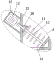
FIG. 2 is an enlarged view of portion A of FIG. 1;
fig. 3 is a schematic view of the top cross-sectional structure of the crushing box and the gear box of the present invention.
In the figure: 1. a shotcrete machine body; 2. a stirring box; 3. a filter screen; 4. a crushing box; 5. a rotating shaft; 6. a drum; 7. a gear case; 8. a gear; 9. a first motor; 10. rotating the rod; 11. a stirring rod; 12. a second motor; 13. a coupling; 14. a discharge port; 15. a mounting frame; 16. a wedge plate; 17. a first connecting pipe; 18. extruding the block; 19. a sloping plate; 20. a second connecting pipe.
Detailed Description
The technical solutions in the embodiments of the present invention will be described clearly and completely with reference to the accompanying drawings in the embodiments of the present invention, and it is obvious that the described embodiments are only some embodiments of the present invention, not all embodiments. Based on the embodiments in the present invention, all other embodiments obtained by a person skilled in the art without creative work belong to the protection scope of the present invention.
Referring to fig. 1-3, the present invention provides a technical solution: a patching machine with a breaking function comprises a patching machine body 1, wherein a stirring box 2 is fixedly installed at the top of the patching machine body 1, an opening is formed in the top of the stirring box 2, a filter screen 3 is fixedly installed in the stirring box 2, a breaking box 4 is fixedly installed at one side of the stirring box 2, two rotating shafts 5 are arranged in the breaking box 4, two ends of each rotating shaft 5 are respectively and rotatably connected with the inner walls of two sides of the breaking box 4, a roller 6 is fixedly installed on each rotating shaft 5, a gear box 7 is fixedly installed at one side of each breaking box 4, the same ends of the two rotating shafts 5 extend into the gear box 7 and are fixedly provided with gears 8, the two gears 8 are meshed with each other, a first motor 9 is fixedly installed at one side of the gear box 7, an output shaft of the first motor 9 is fixedly connected with the corresponding rotating shaft 5, a rotating rod 10 is arranged in the stirring box 2;
a mounting frame 15 is fixedly mounted on one side of the stirring box 2, a second motor 12 is fixedly mounted on the mounting frame 15, a coupler 13 is fixedly mounted on an output shaft of the second motor 12, one end of a rotating rod 10 extends out of the stirring box 2 and is rotatably connected with the stirring box 2, one end of the rotating rod 10 is fixedly connected with the coupler 13, a wedge-shaped plate 16 is fixedly mounted on the inner wall of one side of the stirring box 2, a first fixed block is welded at the bottom of the wedge-shaped plate 16, a second fixed block is welded on the inner wall of the bottom of the stirring box 2, the top of the second fixed block is fixedly connected with the inner wall of one side of the stirring box 2, the first fixed block and the second fixed block are both rotatably connected with the rotating rod 10, a discharge port 14 is formed at the bottom of the stirring box 2, a first connecting pipe 17 and a second connecting pipe 20 are fixedly mounted on the inner wall of one, a plurality of squeezing blocks 18 are welded on the two rollers 6, an inclined plate 19 is arranged below the two rollers 6, the inclined plate 19 is fixedly connected with the inner wall of the crushing box 4, the slurry spraying material is put into the crushing box from an opening on the stirring box 2 through the matching of the slurry spraying machine body 1, the stirring box 2, the filter screen 3, the crushing box 4, the rotating shaft 5, the rollers 6, the gear box 7, the gear 8, the first motor 9, the rotating rod 10, the stirring rod 11, the second motor 12, the coupler 13, the discharge port 14, the mounting frame 15, the wedge-shaped plate 16, the first connecting pipe 17, the squeezing blocks 18, the inclined plate 19 and the second connecting pipe 20, the second motor 12 is started to stir the material entering the stirring box 2, the larger stones can be filtered out through the filter screen 3 and enter the crushing box 4 through the first connecting pipe 17, the first motor 9 is started at this time, the first motor 9 rotates to drive the corresponding rotating shaft 5 to rotate, the rotating shafts 5 drive the corresponding gears 8 to rotate, the gears 8 drive the other gear 8 to rotate, so that the other rotating shaft 5 rotates, the rotating directions of the two gears 8 are opposite, the two rotating shafts 5 drive the two rollers 6 to rotate, the rollers 6 drive the extrusion blocks 18 to rotate, the rotation directions of the two rollers 6 are opposite due to the rotation directions of the two gears 8, and the larger stones are crushed by the cooperation of the pressing blocks 18, and the crushed stones fall onto the inclined plate 19 and enter the stirring tank 2 through the second connecting pipe 20, at this time, because second motor 12 is started, second motor 12 passes through shaft coupling 13 and drives dwang 10 and rotate, and dwang 10 drives puddler 11 and rotates, and puddler 11 stirs the material that enters into agitator tank 2, and the material after the stirring enters into patching machine body 1 through discharge gate 14 in, patching machine body 1 can carry out the whitewashing. The utility model is simple in operation, convenient to use can filter out and be broken with great stone, avoids great stone to block up the whitewashing pipeline and causes the damage and the work efficiency reduction of equipment.
The working principle is as follows: when in use, the guniting material is put into the stirring box 2 from the opening, the second motor 12 is started to stir the material entering the stirring box 2, the larger stones can be filtered out through the filtering of the filtering net 3 and enter the crushing box 4 through the first connecting pipe 17, at the moment, the first motor 9 is started, the first motor 9 rotates to drive the corresponding rotating shaft 5 to rotate, the rotating shaft 5 drives the corresponding gear 8 to rotate, the gear 8 drives the other gear 8 to rotate, so that the other rotating shaft 5 rotates, the rotating directions of the two gears 8 are opposite, the two rotating shafts 5 drive the two rollers 6 to rotate, the rollers 6 drive the extruding block 18 to rotate, the rotating directions of the two rollers 6 are opposite because the rotating directions of the two gears 8 are opposite, the larger stones are extruded and crushed through the matching of the extruding block 18, and the extruded stones fall onto the inclined plate 19, enter into agitator tank 2 through second connecting pipe 20 in, at this moment, because second motor 12 is started, second motor 12 passes through shaft coupling 13 and drives dwang 10 and rotate, dwang 10 drives puddler 11 and rotates, and puddler 11 stirs the material that enters into agitator tank 2, and the material after the stirring passes through discharge gate 14 and enters into patching machine body 1 in, and patching machine body 1 can carry out the whitewashing.
The above, only be the concrete implementation of the preferred embodiment of the present invention, but the protection scope of the present invention is not limited thereto, and any person skilled in the art is in the technical scope of the present invention, according to the technical solution of the present invention and the utility model, the concept of which is equivalent to replace or change, should be covered within the protection scope of the present invention.
Claims (6)
1. The utility model provides a patching machine with crushing function, includes patching machine body (1), its characterized in that: the top fixed mounting of patching machine body (1) has agitator tank (2), the top of agitator tank (2) is equipped with the opening, fixed mounting has filter screen (3) in agitator tank (2), one side fixed mounting of agitator tank (2) has broken case (4), be equipped with two axis of rotation (5) in broken case (4), two the both ends of axis of rotation (5) respectively with the both sides inner wall rotation of broken case (4) is connected, two equal fixed mounting has cylinder (6) on axis of rotation (5), one side fixed mounting of broken case (4) has gear box (7), two the same end of axis of rotation (5) all extends to in gear box (7) and fixed mounting has gear (8), two gear (8) mesh mutually, one side fixed mounting of gear box (7) has first motor (9), the output shaft and corresponding axis of rotation (5) fixed connection of first motor (9), be equipped with dwang (10) in agitator tank (2), the welding has a plurality of puddlers (11) on dwang (10).
2. A shotcrete machine having a crushing function as claimed in claim 1, wherein: one side fixed mounting of agitator tank (2) has mounting bracket (15), fixed mounting has second motor (12) on mounting bracket (15), fixed mounting has shaft coupling (13) on the output shaft of second motor (12), the one end of dwang (10) extends to agitator tank (2) outer and with agitator tank (2) rotate and are connected, the one end of dwang (10) with shaft coupling (13) fixed connection.
3. A shotcrete machine having a crushing function as claimed in claim 1, wherein: fixed mounting has wedge board (16) on one side inner wall of agitator tank (2), the bottom welding of wedge board (16) has first fixed block, the welding has the second fixed block on the bottom inner wall of agitator tank (2), the top of second fixed block with one side inner wall fixed connection of agitator tank (2), first fixed block with the second fixed block all with dwang (10) rotate the connection.
4. A shotcrete machine having a crushing function as claimed in claim 1, wherein: and a discharge hole (14) is formed in the bottom of the stirring box (2).
5. A shotcrete machine having a crushing function as claimed in claim 1, wherein: a first connecting pipe (17) and a second connecting pipe (20) are fixedly mounted on the inner wall of one side of the stirring box (2), and the first connecting pipe (17) and the second connecting pipe (20) are communicated with the crushing box (4).
6. A shotcrete machine having a crushing function as claimed in claim 1, wherein: a plurality of squeezing blocks (18) are welded on the two rollers (6), an inclined plate (19) is arranged below the two rollers (6), and the inclined plate (19) is fixedly connected with the inner wall of the crushing box (4).
Priority Applications (1)
| Application Number | Priority Date | Filing Date | Title |
|---|---|---|---|
| CN201921193161.1U CN210317337U (en) | 2019-07-26 | 2019-07-26 | Patching machine with crushing function |
Applications Claiming Priority (1)
| Application Number | Priority Date | Filing Date | Title |
|---|---|---|---|
| CN201921193161.1U CN210317337U (en) | 2019-07-26 | 2019-07-26 | Patching machine with crushing function |
Publications (1)
| Publication Number | Publication Date |
|---|---|
| CN210317337U true CN210317337U (en) | 2020-04-14 |
Family
ID=70126199
Family Applications (1)
| Application Number | Title | Priority Date | Filing Date |
|---|---|---|---|
| CN201921193161.1U Expired - Fee Related CN210317337U (en) | 2019-07-26 | 2019-07-26 | Patching machine with crushing function |
Country Status (1)
| Country | Link |
|---|---|
| CN (1) | CN210317337U (en) |
Cited By (1)
| Publication number | Priority date | Publication date | Assignee | Title |
|---|---|---|---|---|
| CN113428654A (en) * | 2021-07-31 | 2021-09-24 | 安徽科技学院 | Negative pressure feeding equipment is used in production of ABC powder fire extinguishing agent |
-
2019
- 2019-07-26 CN CN201921193161.1U patent/CN210317337U/en not_active Expired - Fee Related
Cited By (1)
| Publication number | Priority date | Publication date | Assignee | Title |
|---|---|---|---|---|
| CN113428654A (en) * | 2021-07-31 | 2021-09-24 | 安徽科技学院 | Negative pressure feeding equipment is used in production of ABC powder fire extinguishing agent |
Similar Documents
| Publication | Publication Date | Title |
|---|---|---|
| CN216031613U (en) | Concrete intelligence conveyor for construction | |
| CN209179007U (en) | Concrete-spouting plant is used in a kind of preparation of high-strength concrete pipe pile | |
| CN213793317U (en) | An energy-saving and environmentally friendly concrete pouring device | |
| CN209737987U (en) | Can screen mortar machine for building | |
| CN216368187U (en) | Building rubbish reducing mechanism for building engineering | |
| CN221734336U (en) | A device for cleaning accumulated materials | |
| CN213678532U (en) | A dry-mixed mortar residual material recovery device | |
| CN211160165U (en) | Broken cleaning device of building cement waste material | |
| CN210826996U (en) | Highway construction is with batching mixer | |
| CN2389728Y (en) | Reciprocating wet concrete sprayer | |
| CN219081026U (en) | Concrete pumping device convenient to clean | |
| CN217046984U (en) | Prevent concrete mixing equipment's of jam water jet equipment | |
| CN112720845B (en) | Cement mixing plant for building field | |
| CN210032646U (en) | Be used for high pressure grout to prevent stifled device | |
| CN216654721U (en) | A breaker for hydraulic and hydroelectric engineering | |
| CN213890628U (en) | High-wear-resistance gypsum mortar stirring device for building construction | |
| CN212554410U (en) | Concrete mixing device for construction | |
| CN212681120U (en) | Concrete waste recovery device for civil engineering | |
| CN213254638U (en) | Dust fall reducing mechanism for recycled concrete | |
| CN216329122U (en) | A kind of civil engineering material mixing configuration device | |
| CN112125585A (en) | Inorganic material for reinforcement | |
| CN216705435U (en) | Be used for environmental protection engineering construction to use garbage collection device | |
| CN219910010U (en) | Building compounding guniting robot | |
| CN214864275U (en) | Concrete reducing mechanism convenient to transportation for highway construction | |
| CN217451359U (en) | Multi-group feeding device for dry-mixed mortar processing |
Legal Events
| Date | Code | Title | Description |
|---|---|---|---|
| GR01 | Patent grant | ||
| GR01 | Patent grant | ||
| CF01 | Termination of patent right due to non-payment of annual fee |
Granted publication date: 20200414 Termination date: 20210726 |
|
| CF01 | Termination of patent right due to non-payment of annual fee |