Four-cutter-base grooving and chamfering machine
Technical Field
The utility model belongs to the technical field of fluting cornering machine, concretely relates to four tool holders fluting cornering machines.
Background
A paper packaging and printing company has a process of slotting and chamfering paper boards forming a paper box in the production process, at present, most paper packaging and printing companies adopt a four-linkage slotting and chamfering machine which is assembled on a roller by four groups of hanging rings, and the slotting size is set by debugging the hanging rings, for example, a patent with the application number of CN201821040251.2 discloses a paper board slotting and chamfering machine, which belongs to the technical field of paper box production equipment and solves the technical problem that the slotting position of the paper board is easy to bend in the prior art, the paper packaging and printing company comprises a frame, a workbench and a rotating device, wherein the frame is provided with a slotting device which is used for slotting and chamfering the paper board and is positioned below the rotating device, the workbench is provided with a limiting device which is used for limiting the slotting position of the paper board, the limiting device comprises two limiting plates which are connected with the workbench in a sliding way and are arranged at intervals, and the paper board is positioned between the two, the bottom surface of limiting plate sets firmly the limiting slide block that the cross section personally submits the convex setting, and the workstation is seted up the spacing recess with limiting slide block looks adaptation along its length direction, is provided with the fixed subassembly that realizes the limiting plate is fixed between limiting slide block and the workstation. Above-mentioned utility model's cardboard fluting cornering machine through set up stop device on the workstation, makes it have the stable advantage of injecing the cardboard fluting position, has improved the qualification rate of product.
However, the above solution has the following disadvantages in use: when the scheme is used for processing, if the paper board cannot be pulled out in time, multiple grooving and corner cutting can be formed on the paper board, the processing quality is affected, and the defective rate is not reduced.
SUMMERY OF THE UTILITY MODEL
An object of the utility model is to provide a four tool holders fluting cornering machines to solve the problem that proposes among the above-mentioned background art.
In order to achieve the above object, the utility model provides a following technical scheme: the utility model provides a four blade holder fluting cornering machines, includes that four groups install the fluting corner cut mechanism on the bottom plate through the bolt interval, the bottom plate is installed in the frame, the both ends welded fastening of bottom plate has the fixed plate, two be connected with the drive roller through the pivot between the fixed plate, fluting corner cut mechanism passes through the bolt fastening in the mounting groove of bottom plate, fluting corner cut mechanism includes cornering machine blade holder and cornering machine cutting board, the one end of cornering machine cutting board is installed on the hank support of cornering machine blade holder tip through the round pin hub rotation, the cornering machine cutting board is articulated with the branch bottom, branch top and sliding sleeve welding, the sliding sleeve activity is cup jointed on the drive roller, the gearbox is installed to one side of hank support, the bottom welding of gearbox has the sleeve pipe, the intraductal ejector pin that is equipped with, the tip welding of ejector pin has the.
Preferably, a gear box is mounted on one of the fixing plates, the output end of the gear box is connected with the rotating shaft, and the input end of the gear box is connected with a motor mounted on the rack.
Preferably, the drive roller is eccentrically disposed from the rotating shaft.
Preferably, the surfaces of the two ends of the bottom plate are provided with sliding grooves, and limiting plates are mounted in the sliding grooves through bolts.
Preferably, the pin shaft is fixedly connected with a cutting board of the corner cutting machine, the pin shaft is rotatably connected with the hinge support, and one end of the pin shaft is fixed with a driving tooth.
Preferably, the gearbox includes gearbox shell, gearbox shell internal rotation is equipped with the transmission shaft, install drive tooth and driving tooth on the transmission shaft, driving tooth and driving tooth meshing.
Preferably, an output gear is further installed in the transmission case and meshed with the driving teeth, a toothed plate is arranged on the surface of the ejector rod and meshed with the driving teeth and the output gear.
The utility model discloses a technological effect and advantage: this practicality is through at fluting corner cut mechanism side-mounting gearbox for ejector pin and corner cut machine cutting plate keep the simultaneous movement, thereby after accomplishing cardboard fluting corner cut, it is ejecting with the cardboard automatically, prevent that the cardboard from not in time taking out and causing repeated fluting corner cut, reduced the defective percentage.
Drawings
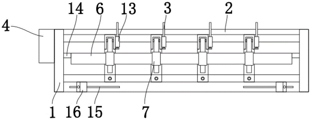
Fig. 1 is a schematic top view of the present invention;
FIG. 2 is a schematic side view of the grooving and chamfering mechanism of the present invention;
fig. 3 is a schematic diagram of the transmission structure of the present invention.
In the figure: the automatic angle cutting machine comprises a fixing plate 1, a bottom plate 2, a push rod 3, a gear box 4, a hinge support 5, a driving roller 6, a sliding sleeve 7, a supporting rod 8, a corner cutting machine knife plate 9, a corner cutting machine knife seat 10, a push plate 11, a sleeve 12, a gear box 13, a gear box 131, a gear box 132, driving teeth 133, a transmission shaft 134, an output gear 135, a rotating shaft 14, a sliding groove 15, a limiting plate 16, a pin shaft 17 and driving teeth 18.
Detailed Description
The technical solutions in the embodiments of the present invention will be described clearly and completely below with reference to the embodiments of the present invention, and it is obvious that the described embodiments are only some embodiments of the present invention, not all embodiments. Based on the embodiments in the present invention, all other embodiments obtained by a person skilled in the art without creative work belong to the protection scope of the present invention.
As shown in fig. 1-3, a four-blade seat grooving and corner-cutting machine comprises four groups of grooving and corner-cutting mechanisms mounted on a base plate 2 at intervals through bolts, wherein the base plate 2 is mounted on a frame, two ends of the base plate 2 are fixedly welded with fixed plates 1, a driving roller 6 is connected between the two fixed plates 1 through a rotating shaft 14, the grooving and corner-cutting mechanisms are fixed in mounting grooves of the base plate 2 through bolts, each grooving and corner-cutting mechanism comprises a corner-cutting machine blade seat 10 and a corner-cutting machine blade plate 9, one end of the corner-cutting machine blade plate 9 is rotatably mounted on a hinge support 5 at the end part of the corner-cutting machine blade seat 10 through a pin shaft 17, the corner-cutting machine blade plate 9 is hinged with the bottom end of a support rod 8, the top end of the support rod 8 is welded with a sliding sleeve 7, the sliding sleeve 7 is movably sleeved on the driving roller 6, a gearbox 13 is, an ejector rod 3 is arranged in the sleeve 12, and a push plate 11 is welded at the end part of the ejector rod 3.
One of the fixing plates 1 is provided with a gear box 4, the output end of the gear box 4 is connected with a rotating shaft 14, and the input end of the gear box 4 is connected with a motor arranged on the rack. The motor is used for driving the rotating shaft 14 to rotate, and then the driving roller 6 is driven to rotate.
The drive roller 6 is arranged eccentrically to the rotation shaft 14. The turning radius of the driving roller 6 is increased, so that the opening and closing range of the cutting board 9 of the angle cutting machine is increased.
The two end surfaces of the bottom plate 2 are provided with sliding grooves 15, and limiting plates 16 are mounted in the sliding grooves 15 through bolts. Through the distance of adjustment limiting plate 16, can carry on spacingly to the cardboard of putting into, avoid the slope, improve fluting corner cut precision.
The pin shaft 17 is fixedly connected with the corner cutting machine cutting board 9, the pin shaft 17 is rotatably connected with the hinge support 5, and one end of the pin shaft 17 is fixed with a driving tooth 18.
The gearbox 13 comprises a gearbox shell 131, a transmission shaft 133 is arranged in the gearbox shell 131 in a rotating mode, a driving tooth 132 and a transmission tooth 134 are mounted on the transmission shaft 133, and the transmission tooth 134 is meshed with the driving tooth 18. The rotation state of the pin 17 can be transmitted to the transmission case 13 by using the driving teeth 18.
Still install output gear 135 in the transmission housing 131, output gear 135 and drive tooth 132 meshing, the surface of ejector pin 3 is equipped with the pinion rack, and pinion rack and drive tooth 132 and output gear 135 meshing. The gear box 13 is used for driving the top rod 3, so that the push plate 11 at the end part of the top rod 3 is pushed to push out the cut paper board. By utilizing the high gear ratio of the driving gear 18 and the transmission gear 134, the rotating speed of the transmission shaft 133 is increased, the tangential speeds of the driving gear 132 and the output gear 135 are increased, and the small-angle action of the cutting board 9 of the corner cutting machine is realized to form the long-distance motion of the ejector rod 3.
Specifically, during the use, adjust the interval of grooving corner cut mechanism and use the bolt to fix according to cutting size, later adjustment limiting plate 16's position, the starter motor drive roller 6 rotates behind the switch on, thereby drive corner cutter cutting board 9 up-and-down motion, carry out the fluting corner cut to the cardboard that gets into, because round pin axle 17 keeps synchronous with the rotation of corner cutter cutting board 9, consequently, can utilize gearbox 13 to promote ejector pin 3, when corner cutter cutting board 9 opens, the fluting corner cut has been accomplished this moment, ejector pin 3 stretches out outwards, utilize push pedal 11 to release the cardboard, when corner cutter cutting board 9 was closed, ejector pin 3 withdraws backward, be convenient for push new cardboard and process.
Finally, it should be noted that: although the present invention has been described in detail with reference to the foregoing embodiments, it will be apparent to those skilled in the art that modifications and variations can be made in the embodiments or in part of the technical features of the embodiments without departing from the spirit and the scope of the invention.