Tool apron for machining numerical control lathe
Technical Field
The utility model relates to a numerical control lathe technical field specifically is a blade holder of numerical control lathe processing usefulness.
Background
With the vigorous development of the domestic equipment manufacturing industry, as the machine tool industry of equipment manufacturing mother machines, in order to meet the high-speed high-precision machining requirements of various different industries, a batch of high-speed, high-precision and high-flexibility combined machining type machine tools are vigorously developed; numerical control lathe blade holder mostly adopts the bolt side by side to fix its lathe tool on the existing market, when the lathe tool was installed, need rotate fixing bolt in proper order just can be fixed with its lathe tool, and the fixing bolt who sets up side by side is different to the pressure of handle of a knife for handle of a knife surface atress is uneven, and the installation effectiveness is low, and direct and the handle of a knife contact in fixing in-process fixing bolt bottom simultaneously causes the handle of a knife surface impaired easily, to the not enough of current device, the utility model discloses a blade holder of numerical control lathe processing usefulness.
SUMMERY OF THE UTILITY MODEL
Technical problem to be solved
Not enough to prior art, the utility model provides a blade holder of numerical control lathe processing usefulness has solved the problem that current device lathe tool installation effectiveness is low.
(II) technical scheme
In order to achieve the above purpose, the utility model discloses a following technical scheme realizes: a tool apron for machining a numerical control lathe comprises a tool apron and a lathe tool, wherein the interior of the tool apron is fixedly inserted with the lathe tool, the turning tool comprises a tool bit and a tool handle, a through groove is horizontally arranged in the tool holder, an inner groove is arranged at the inner top of the through groove, the bottom of the inner groove is communicated with the through groove, the top of the tool apron is provided with a fixing bolt, the threaded end of the fixing bolt drives the tool apron and extends into the inner groove, a pressing block is horizontally arranged in the inner groove, the bottom end of the fixing bolt is connected with a pressing block bearing through a connecting bearing, a first bolt seat is arranged on the upper surface of the cutter seat and positioned at the joint of the fixing bolt and the cutter seat, the inner ring of the first bolt seat is in threaded connection with the fixing bolt, the top of the inner wall of the inner groove is provided with a vertical through hole, the inside of vertical through-hole is provided with balance mechanism, the right side of blade holder is provided with tool retracting mechanism.
Preferably, the connecting bearing comprises an inner ring, an outer ring and balls, the balls are annularly arranged between the inner ring and the outer ring, the inner wall of the inner ring is welded and fixed with the fixing bolt, and the bottom of the outer ring is welded and fixed with the pressing block.
Preferably, the balance mechanism includes spacing ring, connecting rod and spring, the bottom opening part and the spacing ring welded fastening of vertical through-hole, just the bottom and the inner groovy of spacing ring flush, the inside of vertical through-hole is provided with the connecting rod, the one end of connecting rod is passed the spacing ring and is extended to the inside and the briquetting welded fastening of inner groovy, the inside of vertical through-hole is provided with the spring, the inner circle and the connecting rod activity of spring cup joint, the top and the connecting block welded fastening who sets up on the connecting rod top of spring.
Preferably, the tool retracting mechanism comprises a second bolt seat, a rotating bolt and a connecting block, the threaded end of the rotating bolt vertically penetrates through the right side of the tool apron and extends into the through groove, the threaded end of the rotating bolt is fixedly connected with the connecting block, the second bolt seat is fixedly arranged at the joint of the rotating bolt and the tool apron, and the inner ring of the second bolt seat is in threaded connection with the rotating bolt.
Preferably, the perpendicular bisector of the fixing bolt coincides with the vertical perpendicular bisector of the inner groove.
Preferably, the number of the balance mechanisms is two, and the two balance mechanisms are symmetrically arranged around the fixing bolt.
The utility model provides a blade holder of numerical control lathe processing usefulness, its beneficial effect who possesses as follows:
1. this blade holder of numerical control lathe processing usefulness, through setting up fixing bolt, the briquetting, connect the bearing, the spacing ring, connecting rod and spring, the upper surface both sides and the connecting rod fixed connection of briquetting, through rotating fixing bolt, fixing bolt drives the briquetting downstream and extrudees with the handle of a knife contact, in fixing bolt downstream, briquetting upper surface both sides extrude the spring with the connecting rod, thereby make the briquetting receive the pretightning force and keep keeping level and handle of a knife contact, thereby realize installing the lathe tool fast, greatly improve the installation effectiveness.
2. This blade holder of numerical control lathe processing usefulness through setting up second bolt seat, rotating bolt and connecting block, rotates the bolt through rotating, rotates the connecting block that bolt one end set up and extrudees the handle of a knife to promote the handle of a knife to leading to the groove opening part removal, be convenient for realize the separation of lathe tool and blade holder.
Drawings
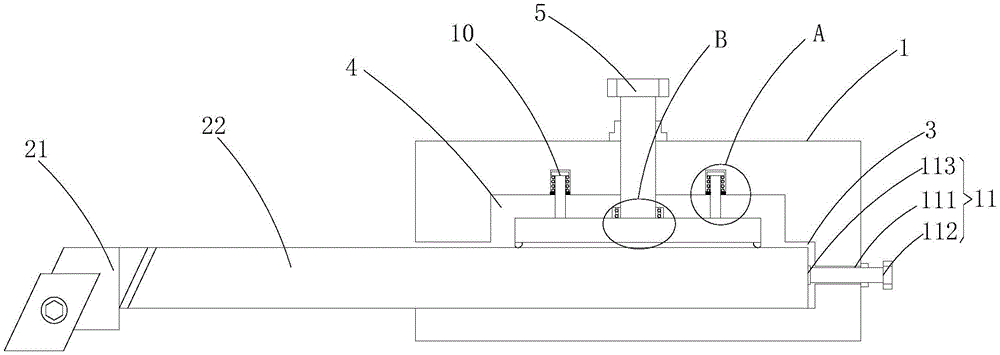
FIG. 1 is a sectional view of the present invention;
FIG. 2 is an enlarged view of the point B in FIG. 1 according to the present invention;
FIG. 3 is an enlarged view of the point A of FIG. 1 according to the present invention;
fig. 4 is a schematic structural diagram of the present invention.
In the figure: the tool comprises a tool apron 1, a turning tool 2, a tool bit 21, a tool holder 22, a through groove 3, an inner groove 4, a fixing bolt 5, a pressing block 6, a connecting bearing 7, an inner ring 71, an outer ring 72, a ball 73, a first bolt seat 8, a vertical through hole 9, a balance mechanism 10, a limiting ring 101, a connecting rod 102, a spring 103, a tool retracting mechanism 11, a second bolt seat 111, a rotating bolt 112 and a connecting block 113.
Detailed Description
The embodiment of the utility model provides a blade holder for numerical control lathe processing, as shown in figure 1-4, including blade holder 1 and lathe tool 2, the inside of blade holder 1 is pegged graft fixedly with lathe tool 2, lathe tool 2 includes tool bit 21 and handle of a knife 22, handle of a knife 22 is pegged graft with logical groove 3 activity, the inside level of blade holder 1 is seted up logical groove 3, the interior top of logical groove 3 is seted up inner groovy 4, the bottom of inner groovy 4 is linked together with logical groove 3, the top of blade holder 1 is provided with fixing bolt 5, the plumb line of fixing bolt 5 coincides with the vertical plumb line of inner groovy 4, the screw end of fixing bolt 5 drives blade holder 1 and extends to the inside of inner groovy 4, the inside level of inner groovy 4 is provided with briquetting 6, briquetting 6 bottom both sides are connected with the lug, briquetting upper surface 6 both sides and connecting rod 102 extrude spring 103, make briquetting 6, the bottom end of the fixing bolt 5 is in bearing connection with the pressing block 6 through the connecting bearing 7, the connecting bearing 7 comprises an inner ring 71, an outer ring 72 and balls 73, the balls 73 are annularly arranged between the inner ring 71 and the outer ring 72, the inner wall of the inner ring 71 is welded and fixed with the fixing bolt 5, the bottom of the outer ring 72 is welded and fixed with the pressing block 6, a first bolt seat 8 is arranged on the upper surface of the tool apron 1 and positioned at the joint of the fixing bolt 5 and the tool apron 1, the inner ring of the first bolt seat 8 is in threaded connection with the fixing bolt 5, a vertical through hole 9 is formed in the top of the inner wall of the inner groove 4, a balance mechanism 10 is arranged inside the vertical through hole 9, the balance mechanism 10 comprises a limiting ring 101, a connecting rod 102 and a spring 103, the opening at the bottom end of the vertical through hole 9 is welded and fixed with the limiting ring 101, the bottom of the limiting ring 101 is flush with the inner groove 4, the connecting rod 102 is arranged inside, a spring 103 is arranged in the vertical through hole 9, the inner ring of the spring 103 is movably sleeved with the connecting rod 102, the top end of the spring 103 is welded and fixed with a connecting block arranged at the top end of the connecting rod 102, the number of the balance mechanisms 10 is two, the two balance mechanisms 10 are symmetrically arranged about the fixing bolt 5, the right side of the tool apron 1 is provided with a tool retracting mechanism 11, the tool retracting mechanism 11 comprises a second bolt seat 111, a rotating bolt 112 and a connecting block 113, the threaded end of the rotating bolt 112 vertically penetrates through the right side of the tool apron 1 and extends into the through groove 3, the threaded end of the rotating bolt 112 is fixedly connected with the connecting block 113, the joint of the rotating bolt 112 and the tool apron 1 is fixedly provided with the second bolt seat 111, the inner ring of the second bolt seat 111 is in threaded connection with the rotating bolt 112, the rotating bolt 112 is rotated, the connecting block 113 arranged at one end of the rotating bolt 112 extrud, the separation of the turning tool 2 and the tool apron 1 is convenient to realize.
The working principle is as follows: the device is when using, through rotating fixing bolt 5, fixing bolt 5 drives briquetting 6 downstream and extrudees with handle of a knife 22 contact, in fixing bolt 5 downstream, briquetting 6 upper surface both sides extrude spring 103 with connecting rod 102, make briquetting 6 receive the pretightning force thereby keep keeping the level and handle of a knife 22 contact, thereby realize installing lathe tool 2 fast, when changing the operation, the contra-rotation fixing bolt 5, briquetting 6 and handle of a knife 22 surface separation, then rotate rotation bolt 112, the connecting block 113 that rotation bolt 112 one end set up extrudees handle of a knife 22, thereby promote handle of a knife 22 to leading to the removal of groove 3 opening part, be convenient for realize the separation of lathe tool 2 and blade holder 1.
The basic principles and the main features of the invention and the advantages of the invention have been shown and described above. It will be understood by those skilled in the art that the present invention is not limited to the above embodiments, and that the foregoing embodiments and descriptions are provided only to illustrate the principles of the present invention without departing from the spirit and scope of the present invention. The scope of the invention is defined by the appended claims and equivalents thereof.