SUMMERY OF THE UTILITY MODEL
The utility model aims at providing a hospital nursing car solves the walking in-process, and the dolly leads to the problem that interior medicine of car is broken, surgical equipment damages or other auxiliary materials spill because of vibrations.
In order to achieve the purpose, the utility model provides a hospital nursing vehicle, which comprises a vehicle body, a base, rollers, a motor, a controller and a damping device, wherein the vehicle body is connected to the upper end of the base; the roller comprises a driving wheel, the motor controls the driving wheel to rotate through a transmission device, and the driving wheel is arranged at the side end of the base; the damping device comprises a damper, a transmission rod and an adjusting plate, the adjusting plate is connected with a base, a plurality of mounting holes with different heights are formed in the adjusting plate, one end of the transmission rod is connected with the top of the damper, the other end of the transmission rod can be fixedly connected with any one of the mounting holes, the mounting holes with different heights are connected with the damping coefficient of the damper, and the bottom of the damper is connected with a driving wheel.
Further, the one end that the automobile body was connected to the base is equipped with first limiting plate, and first limiting plate includes first bottom plate and first vertical board, the first vertical board of first bottom plate fixed connection, and first bottom plate is connected in the upper end of base, and on the first bottom plate was located to the automobile body, the side of automobile body was located to first vertical board for carry on spacingly to the automobile body.
Furthermore, the adjusting plate comprises a second bottom plate and a second limiting plate, the second bottom plate is fixedly connected with the second limiting plate, the second bottom plate is connected with the upper end of the base, the vehicle body is arranged on the second bottom plate, and the second limiting plate is arranged at the side end of the vehicle body and used for limiting the vehicle body.
Furthermore, the bumper shock absorber includes elastic component and telescopic link, and the bottom of telescopic link is connected to elastic component one end, and the top of telescopic link is connected to the other end, and the cooperation telescopic link supports the transfer line.
Furthermore, the adjusting rod comprises two telescopic arms and two rotary buttons, the two telescopic arms are respectively connected with the two ends of each rotary button, one end of one telescopic arm is connected with the driving wheel, and one end of the other telescopic arm is connected with the base through the fixing piece.
Furthermore, the upper end of the vehicle body, which is provided with the vehicle door, is also provided with a fixing hole, the fixing hole is connected with a plug board, and the plug board is inserted into the fixing hole to shield the vehicle door.
Furthermore, push rods are arranged on the front side and the rear side of the advancing direction of the vehicle body and fixedly connected with the vehicle body.
Furthermore, the lower end of the push rod is connected with a bumper, and the outer edge of the bumper protrudes out of the outer edge of the vehicle body.
Furthermore, the number of the push rods is four, the number of the corresponding anti-collision devices is four, two push rods are respectively arranged on the front side of the advancing direction of the vehicle body, and the remaining two push rods are arranged on the rear side of the advancing direction of the vehicle body.
The utility model relates to a hospital nursing car compares with prior art, and beneficial effect lies in, hospital nursing dolly is equipped with the motor, does not need artificial propelling movement, and convenient walking, and the nursing dolly is equipped with bumper shock absorber and bumper, and the process of walking can alleviate the vibrations of automobile body and the effort that the striking produced, and then can protect the intact of inside medicine of automobile body, surgical equipment loss or other auxiliary materials.
Detailed Description
It should be understood that the specific embodiments described herein are merely illustrative of the present invention and are not intended to limit the present invention.
The technical solutions in the embodiments of the present invention will be described clearly and completely with reference to the accompanying drawings in the embodiments of the present invention, and it is obvious that the described embodiments are only some embodiments of the present invention, not all embodiments. Based on the embodiments in the present invention, all other embodiments obtained by a person skilled in the art without creative efforts belong to the protection scope of the present invention.
It should be noted that all the directional indicators (such as upper, lower, left, right, front and rear … …) in the embodiments of the present invention are only used to explain the relative position relationship between the components, the motion situation, etc. in a specific posture (as shown in the drawings), and if the specific posture is changed, the directional indicator is also changed accordingly, and the connection may be a direct connection or an indirect connection.
In addition, descriptions in the present application as to "first", "second", and the like are for descriptive purposes only and are not to be construed as indicating or implying relative importance or implicit to the number of technical features indicated. Thus, a feature defined as "first" or "second" may explicitly or implicitly include at least one such feature. In addition, the technical solutions in the embodiments may be combined with each other, but it must be based on the realization of those skilled in the art, and when the technical solutions are contradictory or cannot be realized, such a combination should not be considered to exist, and is not within the protection scope of the present application.
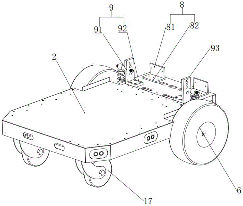
Referring to fig. 1, 2 and 3, the hospital nursing vehicle comprises a vehicle body 1, a base 2, rollers, a motor 3, a controller 4 and a damping device 5, wherein the vehicle body 1 is connected to the upper end of the base 2, the controller 4 is positioned on the front side or the rear side of the advancing direction of the vehicle body 1, the motor 3 is connected to the lower end of the base 2, and the controller 4 is electrically connected with the motor 3; the gyro wheel includes action wheel 6, motor 3 passes through transmission control action wheel 6 and rotates, action wheel 6 sets up in the side of base 2, damping device includes the bumper shock absorber, transfer line 53 and regulating plate 9, base 2 is connected to regulating plate 9, be equipped with a plurality of mounting holes 93 of co-altitude not on the regulating plate 9, the top of bumper shock absorber is connected to the one end of transfer line 53, the other end can be fixed and be connected arbitrary one of them mounting hole 93, connect the mounting hole 93 of co-altitude not in order to change the damping coefficient of bumper shock absorber, action wheel 6 is connected to the bottom of bumper shock absorber.
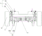
The utility model discloses an in the embodiment, controller 4 control motor 3 drive action wheel 6 walking, and walking in-process damping device 5 carries out the shock attenuation to its automobile body 1. Specifically, the gyro wheel still includes universal wheel 17, the left side and the right side of automobile body 1 direction of advance are located to universal wheel 17, controller 4 locates the rear side middle zone of automobile body 1 direction of advance, the upper end of controller 4 is equipped with directional controller 41, directional controller 41 can be artificial makes action wheel 6 forward, back, left and right four directions rotate, consequently, controller 4 locates the front side or the rear side of automobile body 1 direction of advance, all can conveniently control the automobile body and go towards the direction that the user gos forward, convenience of customers controls the walking of nursing car.
The utility model relates to an embodiment, transfer line 53 and mounting hole 93 screw thread fixed connection, it is concrete, the equidistant mounting hole 93 that is equipped with four co-altitude on regulating plate 9, transfer line 53 sets up when the mounting hole 93 of the co-altitude position of regulating plate 9, the shock-absorbing coefficient that the bumper shock absorber corresponds can produce different changes, correspondingly, the shock-absorbing coefficient of highest point is less than the shock-absorbing coefficient of lowest, the shock attenuation effect is inconsistent, to the weight and the road surface situation of automobile body 1, can select the most suitable mounting hole 93, so that the shock attenuation effect is better. One end of the transmission rod 53 is provided with threads, the mounting hole 93 is a threaded hole, and the transmission rod 53 is in threaded connection with the mounting plate, so that the installation and the replacement after the installation are convenient. The transfer line is connected to the upper end of bumper shock absorber, and the lower extreme passes through base 7 and connects action wheel 6, but base 7 does not hinder action wheel 6 and rolls, and action wheel 6 when rolling, because of rocking that ground unevenness caused, after conduction to base 7, through the damping device 5 who sets up, can reduce the transmission and come shake power, the inside medicine of protection automobile body 1.
In other embodiments, a plurality of damping springs 18 are further disposed between the vehicle body 1 and the base 2, and both ends of the damping springs are fixedly connected to the base 2 and the vehicle body 1, respectively, for further damping the vehicle body 1 and protecting the medicine inside the vehicle body 1.
Referring to fig. 1 and 2, the one end that base 2 connects automobile body 1 is equipped with first limiting plate 8, and first limiting plate 8 includes first bottom plate 82 and first vertical board 81, and first bottom plate 82 fixed connection first vertical board 81, first bottom plate 82 connect in the upper end of base 2, and automobile body 1 is located on first bottom plate 82, and the side of automobile body 1 is located to first vertical board 81 for it is spacing to automobile body 1.
The utility model discloses an in the embodiment, the shape of first limiting plate 8 is L type structure, and is concrete, and first bottom plate 82 and first vertical board 81 are the integrated into one piece structure, make first limiting plate 8, are equipped with three first bottom plate 82 fixed orifices on its first bottom plate 82 for by the mounting pass with base 2 fixed connection, the vertical setting of first vertical board 81 is equipped with two vertical board fixed orifices at the rear side of 1 direction of advance of automobile body on the first vertical board 81, connect at automobile body 1 through the mounting, fix automobile body 1. In the present embodiment, the first limiting plate 8 is provided with two, and two first vertical plates 81 are simultaneously provided on both sides of the rear side of the advancing direction of the vehicle body 1, for further fixing the vehicle body 1.
Referring to fig. 1 and 2, the adjustment plate 9 includes a second bottom plate 91 and a second vertical plate 92, the first bottom plate 82 is fixedly connected to the first vertical plate 81, the second bottom plate 91 is connected to the base 2, and the second vertical plate 92 is connected to a side end of the vehicle body 1 and is close to the driving wheel 6.
The utility model discloses an in the embodiment, the shape of regulating plate 9 is L type structure, and is concrete, and second bottom plate 91 and the vertical board 92 of second are the integrated into one piece structure, make regulating plate 9, are equipped with four second bottom plate 91 fixed orificess on its second bottom plate 91 for being passed by the mounting and carrying out fixed connection with base 2, the vertical setting of the vertical board 92 of second is fixed automobile body 1 in the left side of automobile body 1 direction of advance. In this embodiment, the two adjusting plates 9 are respectively arranged on the left side and the right side of the advancing direction of the vehicle body 1 and used for further fixing the vehicle body 1, and the mounting hole 93 is formed in the second vertical plate to facilitate adjusting the damping coefficient.
Referring to fig. 3, the damper includes an elastic member 51 and an expansion link 52, wherein one end of the elastic member 51 is connected to the bottom of the expansion link 52, and the other end is connected to the top of the expansion link 52, and cooperates with the expansion link 52 to abut against the transmission rod 53.
The utility model discloses an in the embodiment, elastic component 51 is the spring, and when the automobile body rocked, transfer line compression elastic component 51 and telescopic link 52, then the elastic component reduced through elasticity and shakes power to make the telescopic link reconversion, it is concrete, the upper and lower half of telescopic link 52 is the cylinder structure, but the latter half cylinder diameter is greater than the cylinder diameter of the first half, the top of the first half cylinder structure is connected with the roof, the roof upper end is supported and is connected with transfer line 53, the end-to-end connection base 7 of the latter half cylinder structure of telescopic link 52. The telescopic rod 52 is not used for supporting the weight of the vehicle body, but is used for inhibiting the vibration when the spring rebounds after absorbing shock and absorbing the energy of the impact of the driving wheel 6 so as to protect the medicine inside the vehicle body 1.
Referring to fig. 3, the adjusting rod 10 is further included, the adjusting rod 10 includes two telescopic arms 101 and two rotary buttons 102, the two telescopic arms 101 are respectively connected to two ends of the rotary buttons 102, one end of one telescopic arm 101 is connected to the driving wheel 6, and the other end of the adjusting rod 10 is connected to the base 2 through a fixing member.
In one embodiment of the present invention, the length of the adjusting rod 10 is adjustable, specifically, one end of the adjusting rod 10 close to the driving wheel 6 is connected to the driving wheel 6 through the base 7, the end far from the driving wheel 6 is fixedly connected to the speed reducer 11, the speed reducer 11 is fixedly connected to the base 2, therefore, the adjusting rod 10 is fixedly connected with the base 2 through the speed reducer 11, the middle of the adjusting rod 10 is provided with a square rotary button 102, when the rotary button 102 is rotated, the length of the telescopic arm 101 is changed accordingly, when the vehicle bodies 1 having different weights are disposed on the base 2, the weights received on the base 2 are different, the gravity centers of the wheels are inconsistent and the loads are different, which can lead the driving wheel 6 to incline in the walking process, therefore, the driving wheel 6 needs to be corrected by the pull rod, so that the driving wheel 6 does not deviate and tilt when walking, the walking is more stable, and the medicine in the vehicle body 1 is protected.
Referring to fig. 1, the vehicle body 1 is provided with a fixing hole at the upper end of the door 13, the fixing hole is connected with an inserting plate 12, and the inserting plate 12 is inserted into the fixing hole to shield the door 13.
The utility model discloses an in the embodiment, the upper end of automobile body 1 is equipped with the through-hole, and picture peg 12 inserts and carries on spacingly to door 13 in through, and is concrete, and picture peg 12 is for falling L type structure, and door 13 is equipped with two, carries out swivelling joint with the left and right both sides of automobile body 1 respectively, and the upper end of falling L type structure is by through-hole card post, and the lower extreme passes the center that two doors 13 were located to the through-hole to be used for blocking door 13, only need extract when needing to open door 13 picture peg 12 alright, easy operation is convenient.
Referring to fig. 1, push rods 14 are provided on the front and rear sides of the vehicle body 1 in the advancing direction, and the push rods 14 are fixedly connected to the vehicle body 1.
The utility model discloses an in the embodiment, fixedly connected with push rod 14 is still gone back at the both ends of the front side of automobile body 1 direction of advance and rear side, and is concrete, and push rod 14 is vertical to be set up, and the shape is the cylinder structure, and convenience of customers holds push rod 14, can be when motor 3 can not work, and manual the promotion.
Referring to fig. 1, a bumper 15 is connected to a lower end of the push rod 14, and an outer edge of the bumper 15 protrudes from an outer edge of the vehicle body 1.
The utility model discloses an in the embodiment, the disc that bumper 15 was made for plastic materials, fixed connection is at the lower extreme of push rod 14, and the outside edge salient of bumper 15 is in the outside edge of automobile body 1, and in the motion process, automobile body 1 can touch bumper 15 at first when touchhing wall or pedestrian, can alleviate the effort that receives the collision, and then protects the inside medicine of automobile body 1.
In other embodiments, the bumper 15 and the push rod 14 may also be rotatably connected, and when the vehicle collides with a wall, the bumper 15 may rotate around the push rod 14 and along the wall, and a part of the collision force is discharged by rotation, so as to avoid direct collision and damage to the medicine inside the vehicle body 1.
Referring to fig. 1, four push rods 14 are provided, and four corresponding bumpers 15 are provided, two of the push rods 14 are respectively provided at the front side in the advancing direction of the vehicle body 1, and the remaining two push rods 14 are provided at the rear side in the advancing direction of the vehicle body 1.
The utility model discloses an in the embodiment, push rod 14 is equipped with four, and bumper 15 of the equal fixed connection of lower extreme, furtherly, the inside medicine of omnidirectional protection automobile body 1, and can be in the inoperable time of motor 3, when needing to turn around, hold push rod 14 from the other end and promote, reduced in the many and crowded hospital of people, still need manual rotation's troublesome operation.
The utility model relates to a hospital nursing car compares with prior art, and beneficial effect lies in, hospital nursing dolly is equipped with the motor, does not need artificial propelling movement, and convenient walking, and the nursing dolly is equipped with bumper shock absorber and bumper, and the process of walking can alleviate the vibrations of automobile body and the effort that the striking produced, and then can protect the intact of inside medicine of automobile body, surgical equipment loss or other auxiliary materials.
The above only is the preferred embodiment of the present invention, not limiting the scope of the present invention, all the equivalent structures or equivalent flow changes made by the contents of the specification and the drawings, or directly or indirectly applied to other related technical fields, are included in the same way in the protection scope of the present invention.