CN210297868U - Monitoring camera protector based on environment is regulated and control - Google Patents
Monitoring camera protector based on environment is regulated and control Download PDFInfo
- Publication number
- CN210297868U CN210297868U CN201921744650.1U CN201921744650U CN210297868U CN 210297868 U CN210297868 U CN 210297868U CN 201921744650 U CN201921744650 U CN 201921744650U CN 210297868 U CN210297868 U CN 210297868U
- Authority
- CN
- China
- Prior art keywords
- fixedly connected
- plate
- camera
- top surface
- back plate
- Prior art date
- Legal status (The legal status is an assumption and is not a legal conclusion. Google has not performed a legal analysis and makes no representation as to the accuracy of the status listed.)
- Active
Links
Images



Landscapes
- Accessories Of Cameras (AREA)
Abstract
The utility model discloses a surveillance camera head protector based on environment is regulated and control relates to camera accessory technical field. The utility model discloses a back plate, back plate lateral wall pass through screw fixedly connected with mount pad, mount pad top surface fixedly connected with back plate, back plate top end fixedly connected with supports the support, supports the support top and passes through screw fixedly connected with camera, back plate lateral wall fixedly connected with roof, back plate lateral wall fixedly connected with PLC controller, lateral wall fixed connection has wiper mechanism before the roof, the equal fixedly connected with protection machanism in roof top surface both sides, the utility model discloses a combined action of protection machanism and heat dissipation mechanism, camera still can normally work under the lower or higher condition of temperature, ensured the steady operation of surveillance camera head, wiper mechanism can utilize the water stain on the clean camera lens of arc brush in the rainy day simultaneously, and the guarantee camera can normally shoot and photograph.
Description
Technical Field
The utility model relates to a camera accessory technical field specifically is based on the first protector of surveillance camera that the environment regulated and control.
Background
The monitoring system is one of the most applied systems in the security system, the most common equipment in the monitoring system is a monitoring camera, and the monitoring camera is a semiconductor imaging device, has the advantages of high sensitivity, strong light resistance, small distortion, small volume, long service life, vibration resistance and the like, and is generally utilized; the working temperature range of a common monitoring camera is-2-50 ℃, and the monitoring camera is easily damaged and fails when the working temperature is lower or higher than the working temperature.
The protection device for the camera at the present stage mainly aims at waterproof and lightning protection performance, the temperature protection requirement of the camera cannot be well met, the investment cost of a security system is increased due to the fact that the camera is easily damaged in the case of extremely cold and hot summer, meanwhile, the existing camera lens is easily shielded by water stain in rainy days and cannot be shot normally, and therefore the technical problem to be solved by technical personnel in the field is to develop the protection device capable of intelligently regulating and controlling the ambient temperature of the camera.
SUMMERY OF THE UTILITY MODEL
Not enough to prior art, the utility model provides a first protector of surveillance camera based on environment is regulated and control has solved the problem of proposing among the above-mentioned background art.
In order to achieve the above purpose, the utility model discloses a following technical scheme realizes: the monitoring camera protection device based on environment regulation comprises a rear plate, wherein the side wall of the rear plate is fixedly connected with a mounting seat through a screw, the top surface of the mounting seat is fixedly connected with the rear plate, the top end of the rear plate is fixedly connected with a supporting bracket, and the top of the supporting bracket is fixedly connected with a camera through a screw;
the rear plate side wall is fixedly connected with a top plate, the rear plate side wall is fixedly connected with a PLC (programmable logic controller), the front side wall of the top plate is fixedly connected with a wiper mechanism, two sides of the top surface of the top plate are fixedly connected with protection mechanisms, the rear plate side wall is fixedly connected with two heat dissipation mechanisms, the two heat dissipation mechanisms are respectively located on two sides of a camera, and the top surface of the camera is fixedly connected with a temperature and humidity sensor.
Further, wiper mechanism is including being fixed in the driving motor of roof front side wall, driving motor output shaft one end fixedly connected with arc brush, driving motor top surface fixedly connected with waterproof cover, waterproof cover both sides all with roof fixed connection, PLC controller output and driving motor input electric connection.
Further, protection machanism is including being fixed in the pivot of roof top surface, the roof top surface rotates through the pivot and is connected with electric push rod, electric push rod one end rotates and is connected with the engaging lug, engaging lug lateral wall fixedly connected with connecting plate, PLC controller output and electric push rod input electric connection.
Further, electric push rod one end is passed through the engaging lug and is connected with the connecting plate rotation, connecting plate bottom fixedly connected with heat preservation apron, heat preservation apron one side is passed through the hinge and is connected with the roof rotation, heat preservation apron appearance is the arc structure, heat preservation apron intrados fixedly connected with heat preservation.
Furthermore, the heat dissipation mechanism comprises two connecting rods fixed on the side wall of the rear plate, one ends of the two connecting rods are fixedly connected with a connecting piece, the top end of the connecting piece is fixedly connected with the top plate, the peripheral side face of each connecting rod is slidably connected with two sliding blocks, heat dissipation fans are fixedly connected between the four opposite side walls of each sliding block, and the output end of the PLC is electrically connected with the input end of each heat dissipation fan.
Further, two steel pipes are fixedly connected to the rear side wall of the rear plate, and the output end of the temperature and humidity sensor is electrically connected with the input end of the PLC through an electric wire.
The utility model discloses following beneficial effect has:
1. this surveillance camera head protector based on environment is regulated and control through the combined action of protection machanism and heat dissipation mechanism, has enlarged the operating temperature scope of camera, and the camera still can normally work under the lower or higher condition of temperature, has ensured the steady operation of surveillance camera head, has improved the durability of camera.
2. This surveillance camera head protector based on environment is regulated and control through setting up windshield wiper mechanism, can utilize the water stain on the clean camera lens of arc brush in the rainy day, and the guarantee camera can normally shoot and shoot with video-corder, can act as the canopy when the heat preservation apron expandes simultaneously, enlarges protector's rain range that hides, reduces the probability that the camera intake, has improved the security of camera indirectly.
Of course, it is not necessary for any particular product to achieve all of the above-described advantages at the same time.
Drawings
In order to more clearly illustrate the technical solutions of the embodiments of the present invention, the drawings used in the description of the embodiments will be briefly introduced below, and it is obvious that the drawings in the following description are only some embodiments of the present invention, and it is obvious for those skilled in the art that other drawings can be obtained according to these drawings without creative efforts.
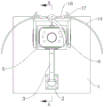
Fig. 1 is a schematic structural view of the present invention;
FIG. 2 is a schematic view of the opposite side of FIG. 1;
FIG. 3 is a schematic front view of the structure of FIG. 1;
fig. 4 is a schematic cross-sectional view taken along line a-a in fig. 3.
In the drawings, the components represented by the respective reference numerals are listed below:
in the figure: 1-a rear plate, 2-a mounting seat, 3-a connecting bracket, 4-a supporting bracket, 5-a camera, 6-a top plate, 7-a driving motor, 8-an arc brush, 9-a connecting piece, 10-a connecting rod, 11-a sliding block, 12-a cooling fan, 13-a waterproof cover, 14-a heat-preservation cover plate, 15-a rotating shaft, 16-an electric push rod, 17-a connecting plate, 18-a steel pipe, 19-a temperature and humidity sensor and 20-a PLC (programmable logic controller).
Detailed Description
The technical solutions in the embodiments of the present invention will be described clearly and completely with reference to the accompanying drawings in the embodiments of the present invention, and it is obvious that the described embodiments are only some embodiments of the present invention, not all embodiments. Based on the embodiments of the present invention, all other embodiments obtained by a person of ordinary skill in the art without creative efforts belong to the protection scope of the present invention.
Referring to fig. 1-4, the present invention provides a technical solution: the monitoring camera protection device based on environment regulation comprises a rear plate 1, wherein the side wall of the rear plate 1 is fixedly connected with a mounting seat 2 through a screw, the top surface of the mounting seat 2 is fixedly connected with the rear plate 1, the top end of the rear plate 1 is fixedly connected with a supporting bracket 4, and the top of the supporting bracket 4 is fixedly connected with a camera 5 through a screw;
the side wall of the rear plate 1 is fixedly connected with a top plate 6, the side wall of the rear plate 1 is fixedly connected with an R-P1188D type PLC (programmable logic controller) 20, the front side wall of the top plate 6 is fixedly connected with a wiper mechanism, two sides of the top surface of the top plate 6 are fixedly connected with a protection mechanism, the side wall of the rear plate 1 is fixedly connected with two heat dissipation mechanisms, the two heat dissipation mechanisms are respectively positioned on two sides of a camera 5, and the top surface of the camera 5 is fixedly connected with an AM2302 type temperature and humidity; the PLC controller 20 is used for power supply and circuit control of the entire apparatus.
The windshield wiper mechanism comprises a driving motor 7 fixed on the front side wall of the top plate 6, one end of an output shaft of the driving motor 7 is fixedly connected with an arc-shaped brush 8, the top surface of the driving motor 7 is fixedly connected with a waterproof cover 13, two sides of the waterproof cover 13 are fixedly connected with the top plate 6, and the output end of the PLC 20 is electrically connected with the input end of the driving motor 7; the waterproof cover 13 can prevent the drive motor 7 from water inlet failure.
The protection mechanism comprises a rotating shaft 15 fixed on the top surface of the top plate 6, the top surface of the top plate 6 is rotatably connected with an ANT-26 model electric push rod 16 through the rotating shaft 15, one end of the electric push rod 16 is rotatably connected with a connecting lug, a connecting plate 17 is fixedly connected to the side wall of the connecting lug, and the output end of the PLC controller 20 is electrically connected with the input end of the electric push rod 16.
One end of the electric push rod 16 is rotatably connected with a connecting plate 17 through a connecting lug, the bottom of the connecting plate 17 is fixedly connected with a heat-insulating cover plate 14, one side of the heat-insulating cover plate 14 is rotatably connected with the top plate 6 through a hinge, the heat-insulating cover plate 14 is of an arc-shaped structure, and the inner arc surface of the heat-insulating cover plate 14 is fixedly connected with a heat-insulating layer; the heat preservation material is the rubber and plastic sponge, and the heat preservation apron 14 is convenient for the better encirclement camera 5 of heat preservation.
The heat dissipation mechanism comprises two connecting rods 10 fixed on the side wall of the rear plate 1, one ends of the two connecting rods 10 are fixedly connected with a connecting piece 9, the top end of the connecting piece 9 is fixedly connected with the top plate 6, the peripheral side surfaces of the connecting rods 10 are connected with two sliding blocks 11 in a sliding mode, heat dissipation fans 12 are fixedly connected between opposite side walls of the four sliding blocks 11, and the output end of the PLC 20 is electrically connected with the input end of each heat dissipation fan 12; according to different models of the camera 5, the two cooling fans 12 can be manually pushed to slide on the connecting rod 10, so that the cooling fans 12 are aligned to the easily-heated part of the camera 5, and the application range of the device is conveniently expanded.
Wherein, the rear side wall of the rear plate 1 is fixedly connected with two steel pipes 18, and the output end of the temperature and humidity sensor 19 is electrically connected with the input end of the PLC 20 through an electric wire; the back plate 1 is mounted to a wall or curb support by inserting bolts into the two steel tubes 18.
The specific application of this embodiment is: connecting a PLC (programmable logic controller) 20 with a power supply line, switching on a power supply of the PLC 20, supplying power to a temperature and humidity sensor 19 by the PLC 20, acquiring temperature and humidity information around the camera 5 by the temperature and humidity sensor 19 in real time, transmitting the temperature and humidity information to the PLC 20 in real time, and judging a change protection mechanism of the environment around the camera 5 by the PLC 20; when the ambient temperature of the camera 5 exceeds 40 ℃, the PLC 20 controls the two electric push rods 16 to contract, the electric push rods 16 drive the two connecting plates 17 to rotate, the connecting plates 17 pull the heat-insulating cover plate 14 to rotate and expand, meanwhile, the PLC 20 controls the two cooling fans 12 to start, the cooling fans 12 blow air to cool the ambient temperature of the camera 5, the camera 5 is prevented from stopping working due to overhigh temperature, and the rain shielding range around the camera 5 can be expanded when the heat-insulating cover plate 14 expands; if the temperature is lower than 0 ℃, the PLC 20 controls the two cooling fans 12 to stop working, and simultaneously controls the two electric push rods 16 to extend, the electric push rods 16 drive the heat-insulating cover plate 14 to rotate and store through pushing the connecting plate 17, the heat-insulating cover plate 14 wraps the two sides of the camera 5, the heat-insulating layer can slow down the heat dissipation of the heat around the camera 5, and the camera 5 is prevented from stopping working due to too low temperature; when the external humidity exceeds 70% RH, the PLC controller 20 controls the driving motor 7 to start, the output shaft of the driving motor 7 rotates in a reciprocating manner to drive the arc brush 8 to wipe the lens of the camera 5, so that the water stain caused by rainfall can be prevented from blocking the lens of the camera 5, and the camera 5 can be ensured to be capable of being shot and recorded normally.
The above, only be the concrete implementation of the preferred embodiment of the present invention, but the protection scope of the present invention is not limited thereto, and any person skilled in the art is in the technical scope of the present invention, according to the technical solution of the present invention and the utility model, the concept of which is equivalent to replace or change, should be covered within the protection scope of the present invention.
Claims (6)
1. First protector of surveillance camera based on environment is regulated and control, including back plate (1), its characterized in that: the side wall of the rear plate (1) is fixedly connected with a mounting seat (2) through a screw, the top surface of the mounting seat (2) is fixedly connected with the rear plate (1), the top end of the rear plate (1) is fixedly connected with a supporting support (4), and the top of the supporting support (4) is fixedly connected with a camera (5) through a screw;
rear panel (1) lateral wall fixedly connected with roof (6), rear panel (1) lateral wall fixedly connected with PLC controller (20), lateral wall fixed connection has the wiper mechanism before roof (6), the equal fixedly connected with protection machanism in roof (6) top surface both sides, two heat dissipation mechanisms of rear panel (1) lateral wall fixedly connected with, two heat dissipation mechanisms are located camera (5) both sides respectively, camera (5) top surface fixedly connected with temperature and humidity sensor (19).
2. The monitoring camera protection device based on environment regulation and control of claim 1, wherein the wiper mechanism comprises a driving motor (7) fixed on the front side wall of the top plate (6), one end of an output shaft of the driving motor (7) is fixedly connected with an arc-shaped brush (8), a waterproof cover (13) is fixedly connected to the top surface of the driving motor (7), both sides of the waterproof cover (13) are fixedly connected with the top plate (6), and the output end of the PLC (20) is electrically connected with the input end of the driving motor (7).
3. The monitoring camera protection device based on environment regulation and control of claim 1, wherein the protection mechanism comprises a rotating shaft (15) fixed on the top surface of the top plate (6), the top surface of the top plate (6) is rotatably connected with an electric push rod (16) through the rotating shaft (15), one end of the electric push rod (16) is rotatably connected with a connecting lug, the side wall of the connecting lug is fixedly connected with a connecting plate (17), and the output end of the PLC (20) is electrically connected with the input end of the electric push rod (16).
4. The monitoring camera protection device based on environment regulation and control of claim 3, wherein one end of the electric push rod (16) is rotatably connected with the connecting plate (17) through a connecting lug, a heat preservation cover plate (14) is fixedly connected to the bottom of the connecting plate (17), one side of the heat preservation cover plate (14) is rotatably connected with the top plate (6) through a hinge, the heat preservation cover plate (14) is of an arc-shaped structure, and a heat preservation layer is fixedly connected to the inner arc surface of the heat preservation cover plate (14).
5. The monitoring camera protection device based on environment regulation and control of claim 1, wherein the heat dissipation mechanism comprises two connecting rods (10) fixed on the side wall of the back plate (1), one end of each of the two connecting rods (10) is fixedly connected with a connecting piece (9), the top end of each connecting piece (9) is fixedly connected with the top plate (6), the side surface of each connecting rod (10) is slidably connected with two sliding blocks (11), a heat dissipation fan (12) is fixedly connected between the four opposite side walls of each sliding block (11), and the output end of the PLC (20) is electrically connected with the input end of the heat dissipation fan (12).
6. The monitoring camera protection device based on environment regulation and control of claim 1, characterized in that two steel pipes (18) are fixedly connected to the rear side wall of the rear plate (1), and the output end of the temperature and humidity sensor (19) is electrically connected with the input end of a PLC (20) through an electric wire.
Priority Applications (1)
| Application Number | Priority Date | Filing Date | Title |
|---|---|---|---|
| CN201921744650.1U CN210297868U (en) | 2019-10-17 | 2019-10-17 | Monitoring camera protector based on environment is regulated and control |
Applications Claiming Priority (1)
| Application Number | Priority Date | Filing Date | Title |
|---|---|---|---|
| CN201921744650.1U CN210297868U (en) | 2019-10-17 | 2019-10-17 | Monitoring camera protector based on environment is regulated and control |
Publications (1)
| Publication Number | Publication Date |
|---|---|
| CN210297868U true CN210297868U (en) | 2020-04-10 |
Family
ID=70066459
Family Applications (1)
| Application Number | Title | Priority Date | Filing Date |
|---|---|---|---|
| CN201921744650.1U Active CN210297868U (en) | 2019-10-17 | 2019-10-17 | Monitoring camera protector based on environment is regulated and control |
Country Status (1)
| Country | Link |
|---|---|
| CN (1) | CN210297868U (en) |
Cited By (4)
| Publication number | Priority date | Publication date | Assignee | Title |
|---|---|---|---|---|
| CN111966029A (en) * | 2020-08-14 | 2020-11-20 | 昆山同日工业自动化有限公司 | Intelligent security monitoring system based on 5G network |
| CN114827402A (en) * | 2022-04-02 | 2022-07-29 | 深圳市世纪乾金技术有限公司 | Outdoor super clear 4G intelligence surveillance camera head |
| CN115489205A (en) * | 2022-10-08 | 2022-12-20 | 安徽天翔高新特种包装材料集团有限公司 | A web printing online detection device |
| CN121194078A (en) * | 2025-08-27 | 2025-12-23 | 上海旋荣科技股份有限公司 | High-voltage transmission line monitoring system |
-
2019
- 2019-10-17 CN CN201921744650.1U patent/CN210297868U/en active Active
Cited By (4)
| Publication number | Priority date | Publication date | Assignee | Title |
|---|---|---|---|---|
| CN111966029A (en) * | 2020-08-14 | 2020-11-20 | 昆山同日工业自动化有限公司 | Intelligent security monitoring system based on 5G network |
| CN114827402A (en) * | 2022-04-02 | 2022-07-29 | 深圳市世纪乾金技术有限公司 | Outdoor super clear 4G intelligence surveillance camera head |
| CN115489205A (en) * | 2022-10-08 | 2022-12-20 | 安徽天翔高新特种包装材料集团有限公司 | A web printing online detection device |
| CN121194078A (en) * | 2025-08-27 | 2025-12-23 | 上海旋荣科技股份有限公司 | High-voltage transmission line monitoring system |
Similar Documents
| Publication | Publication Date | Title |
|---|---|---|
| CN216805379U (en) | Automatic dust removal water tank cover of harvester heat dissipation water tank | |
| CN205092461U (en) | Semiconductor refrigeration and even ventilation cooling device of refrigeration and cooling type switch board | |
| CN203068720U (en) | Ventilation device in communication base station | |
| CN209199503U (en) | A kind of LED display with water-proof function | |
| CN210519300U (en) | Air exchange energy-saving system of communication base station | |
| CN211209770U (en) | Novel environmental protection security protection control device | |
| CN218587235U (en) | Artificial intelligence monitoring device | |
| CN217198064U (en) | Dustproof effectual on-vehicle camera device | |
| CN211982424U (en) | Electronic communication connection box with dustproof heat dissipation function | |
| CN211956086U (en) | Outdoor protector of matrix projector | |
| CN212183612U (en) | Multi-view panoramic monitoring camera with anti-seismic and heat-dissipation functions | |
| CN116538053A (en) | Heat dissipation and dust removal assembly of air compressor | |
| CN111147697A (en) | Intelligent wireless network camera | |
| CN214316012U (en) | Power transmission and transformation cost panorama view display device | |
| CN211261076U (en) | Air conditioner electrical appliance with efficient heat dissipation mechanism | |
| CN115149440A (en) | a power distribution cabinet | |
| CN219550051U (en) | Mounting bracket for camera | |
| CN216626430U (en) | Online integrated management platform of raw and auxiliary materials | |
| CN219660114U (en) | An evaporative cooling air treatment equipment for 5G base stations | |
| CN224080523U (en) | Water chilling unit of integrated type cooling equipment | |
| CN218448133U (en) | Transformer substation energy storage device | |
| CN219352120U (en) | Monitoring and installing equipment with waterproof structure | |
| CN210839764U (en) | Wide dynamic camera of high definition with deashing heat radiation structure | |
| CN218497432U (en) | Distribution thing networking debugging terminal | |
| CN222356829U (en) | Heat dissipation and dust removal device for outdoor advertising machine |
Legal Events
| Date | Code | Title | Description |
|---|---|---|---|
| GR01 | Patent grant | ||
| GR01 | Patent grant |