CN210297484U - Capacitor welding mechanism of assembling equipment for miniature motor - Google Patents
Capacitor welding mechanism of assembling equipment for miniature motor Download PDFInfo
- Publication number
- CN210297484U CN210297484U CN201921426954.3U CN201921426954U CN210297484U CN 210297484 U CN210297484 U CN 210297484U CN 201921426954 U CN201921426954 U CN 201921426954U CN 210297484 U CN210297484 U CN 210297484U
- Authority
- CN
- China
- Prior art keywords
- capacitance
- cylinder
- capacitor
- mounting panel
- component
- Prior art date
- Legal status (The legal status is an assumption and is not a legal conclusion. Google has not performed a legal analysis and makes no representation as to the accuracy of the status listed.)
- Expired - Fee Related
Links
Images
Abstract
The utility model discloses a capacitance welding mechanism of an assembly device for a micro motor, which comprises a frame and a first vibration disk, wherein the first vibration disk is connected with a first vibration track, the tail end of the first vibration track is provided with a moving section, the moving end is driven by an air cylinder, a capacitance arrangement component is arranged in match with the moving section, the moving section is communicated with the first vibration track, after the capacitance is vibrated on the moving section, a moving block is driven by the air cylinder to be parallel to the capacitance arrangement component, the capacitance welding mechanism also comprises a capacitance clamping component and a capacitance welding component, the capacitance clamping component clamps the capacitance arranged by the capacitance arrangement component and places the capacitance on the micro motor, the capacitor welding assembly and the capacitor welding assembly are welded, so that the working efficiency is greatly improved, and the cost is reduced.
Description
Technical Field
The utility model belongs to the technical field of micro motor rigging equipment, concretely relates to micro motor is with electric capacity welding mechanism of equipment.
Background
Micro motor need be with electric capacity and motor body welding when the equipment to and an installation nut on motor body, current equipment mode still adopts manual welding electric capacity mostly, can't realize automated production, and production efficiency is low.
SUMMERY OF THE UTILITY MODEL
An object of the utility model is to provide an equipment's for miniature motor electric capacity welding mechanism to solve the current equipment mode that proposes in the above-mentioned background art, still adopt manual welding electric capacity mostly, can't realize automated production, problem that production efficiency is low.
In order to achieve the above object, the utility model provides a following technical scheme:
the utility model provides a capacitance welding mechanism of equipment for micro motor, includes the frame to and first vibration dish, first vibration dish is connected first vibration track, and first vibration track's end sets up the removal section, removes the end and uses the cylinder drive, with the removal section matches and is provided with the electric capacity and arranges the subassembly, removes section and first vibration track intercommunication, after vibrating electric capacity to remove the section, arranges the subassembly parallel through cylinder drive movable block and electric capacity, still includes electric capacity clamp-up subassembly and electric capacity welding subassembly, electric capacity clamp-up subassembly presss from both sides the electric capacity after the subassembly is arranged to electric capacity to place on micro motor, weld both through electric capacity welding subassembly.
The capacitor is of a U-shaped structure, and two terminals of the capacitor are arranged in the first vibration track through the first vibration disc.
Preferably, the capacitor arrangement assembly comprises a first installation seat fixed on the rack, a first sliding plate is connected onto the first installation seat in a sliding mode, a second sliding plate is connected onto the first sliding plate in a sliding mode, a guide rail frame is fixed onto the second sliding plate, a plurality of arrangement pieces are sleeved on the guide rail frame and are connected with each other in a telescopic rod in a telescopic mode, a first cylinder is connected onto the arrangement pieces located at the end portions, and a plug used for plugging up a capacitor is arranged at the front end of each arrangement piece.
After the capacitors are arranged in the first vibration track, the capacitors are inserted by adjusting the plugs, and the capacitors are stretched by the first air cylinder, so that the arrangement pieces are unfolded on the guide rail frame, namely, the capacitors are arranged at intervals.
The first sliding plate and the first mounting seat are connected with each other through the sliding rail and the sliding block.
Preferably, the capacitor clamping assembly comprises a support frame connected with the frame, a pneumatic clamp and a connecting arm, the pneumatic clamp is hinged to the tail end of the connecting arm, the top of the pneumatic clamp is hinged to a piston rod of a second cylinder, and the second cylinder is fixed on the connecting arm; the connecting arm is movably connected to the supporting frame and moves back and forth relative to the supporting frame.
Preferably, be provided with first slide rail on the support frame, sliding connection has first mounting panel on the first slide rail, and the lateral part of the first mounting panel of perpendicular to is connected with the second mounting panel, linking arm sliding connection in on the second mounting panel, the linking arm for the second mounting panel reciprocates, first mounting panel is connected with the piston rod of third cylinder, promotes first mounting panel through the third cylinder and moves on first slide rail, is fixed with the fourth cylinder on the first mounting panel, the piston rod of fourth cylinder is connected with the linking arm and is driven the linking arm up-and-down motion.
Preferably, the hydraulic support further comprises a fifth cylinder, the fifth cylinder is mounted on the support frame, a piston rod of the fifth cylinder is connected with a welding head, and the welding head is arranged right above the station groove.
The welding head is the prior art and is not described herein again.
After the capacitors are arranged at intervals, the capacitors are clamped through the capacitor clamping assembly, and the top of the pneumatic clamp is hinged to the piston rod of the second cylinder, so that the second cylinder drives the pneumatic clamp to place the capacitors on the micro motor.
Compared with the prior art, the beneficial effects of the utility model are that:
through electric capacity range subassembly, electric capacity clamp subassembly and electric capacity welding subassembly, electric capacity clamp subassembly presss from both sides the electric capacity after the electric capacity range subassembly is arranged to place on micro motor, weld both through electric capacity welding subassembly, improved work efficiency greatly, the cost is reduced.
Drawings
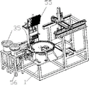
Fig. 1 is a schematic view of the installation structure of the present invention;
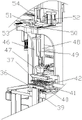
FIG. 2 is a schematic structural view of the capacitive welding mechanism of FIG. 1;
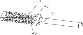
fig. 3 is a schematic structural diagram of the capacitor arrangement assembly of fig. 1.
Detailed Description
The technical solutions in the embodiments of the present invention will be described clearly and completely with reference to the accompanying drawings in the embodiments of the present invention, and it is obvious that the described embodiments are only some embodiments of the present invention, not all embodiments. Based on the embodiments in the present invention, all other embodiments obtained by a person skilled in the art without creative work belong to the protection scope of the present invention.
The utility model provides a capacitor welding mechanism of an assembly device for a miniature motor as shown in figures 1-3, which comprises a frame 1 and a first vibration disk 35, wherein the first vibration disk is connected with a first vibration track, the end of the first vibration track is provided with a moving section 36, and the moving section 36 is provided with a groove body (not shown) communicated with the first vibration track;
the moving end is driven by an air cylinder, a capacitor arrangement component 37 is arranged in a matching manner with the moving section, the moving section is communicated with the first vibration track, and after the capacitor is vibrated on the moving section, a moving block is driven by the air cylinder to be parallel to the capacitor arrangement component;
the capacitor clamping assembly clamps the capacitor arranged by the capacitor arranging assembly and is placed on the micro motor, and the capacitor clamping assembly and the capacitor welding assembly are welded together. The capacitor is of a U-shaped structure, and two terminals of the capacitor are arranged in the first vibration track through the first vibration disc;
the subassembly is arranged to electric capacity is including being fixed in the first mount pad 39 in the frame, sliding connection has first slide 40 on the first mount pad, sliding connection has second slide 41 on the first slide, be fixed with guide rail frame 42 on the second slide, a plurality of arrangement pieces 43, a plurality of have cup jointed on the guide rail frame arrange through the mutual telescopic link between the piece, and be located the arrangement piece of tip and be connected with first cylinder 44, be provided with the plug 45 that is used for inserting electric capacity on arranging the front end of piece, arrange back in first vibration track when electric capacity, the adjusting plug inserts electric capacity, and is tensile through first cylinder, makes a plurality of arrange the piece and expand on the guide rail frame, arrange electric capacity interval arrangement promptly. The capacitor clamping assembly comprises a support frame 46 connected with the frame, a pneumatic clamp 47 and a connecting arm 48, wherein the pneumatic clamp is hinged to the tail end of the connecting arm, the top of the pneumatic clamp is hinged to a piston rod of a second air cylinder 49, and the second air cylinder 49 is fixed on the connecting arm; the connecting arm is movably connected on the supporting frame and moves back and forth relative to the supporting frame, a first sliding rail 50 is arranged on the supporting frame, a first mounting plate 51 is connected on the first sliding rail in a sliding way, a second mounting plate 52 is connected on the side part vertical to the first mounting plate, the connecting arm is slidably connected to the second mounting plate, the connecting arm moves up and down relative to the second mounting plate, the first mounting plate is connected to a piston rod of a third cylinder 53, the first mounting plate is pushed to move on the first slide rail through the third cylinder, the fourth cylinder 54 is fixed on the first mounting plate, the piston rod of the fourth cylinder is connected with the connecting arm to drive the connecting arm to move up and down, and the fourth cylinder also comprises a fifth cylinder 55, the fifth cylinder is installed on the support frame, a piston rod of the fifth cylinder is connected with a welding head 56, and the welding head is arranged right above the station groove.
The welding head is the prior art and is not described herein again.
After the capacitors are arranged at intervals, the capacitors are clamped through the capacitor clamping assembly, and the top of the pneumatic clamp is hinged to the piston rod of the second cylinder, so that the second cylinder drives the pneumatic clamp to place the capacitors on the micro motor.
Finally, it should be noted that: although the present invention has been described in detail with reference to the foregoing embodiments, it will be apparent to those skilled in the art that modifications and variations can be made in the embodiments or in part of the technical features of the embodiments without departing from the spirit and the scope of the invention.
Claims (5)
1. The utility model provides a capacitance welding mechanism of equipment for miniature motor which characterized in that: the electric capacity vibration device comprises a rack and a first vibration disk, wherein the first vibration disk is connected with a first vibration track, the tail end of the first vibration track is provided with a moving section, the moving end is driven by an air cylinder, a capacitance arrangement component is arranged on the moving section in a matched mode, the moving section is communicated with the first vibration track, after the capacitance is vibrated on the moving section, the moving section is driven by the air cylinder to be parallel to the capacitance arrangement component, the electric capacity vibration device further comprises a capacitance clamping component and a capacitance welding component, the capacitance clamping component clamps capacitance arranged by the capacitance arrangement component and is placed on a micro motor, and the capacitance welding component is welded with the capacitance arrangement component.
2. The capacitor welding mechanism of an assembling apparatus for a micro motor according to claim 1, wherein: the capacitor arrangement assembly comprises a first installation seat fixed on the rack, a first sliding plate is connected onto the first installation seat in a sliding mode, a second sliding plate is connected onto the first sliding plate in a sliding mode, a guide rail frame is fixed onto the second sliding plate, a plurality of arrangement pieces are sleeved on the guide rail frame and are connected with each other in a telescopic rod in a telescopic mode, the arrangement pieces located at the end portions are connected with a first cylinder, and a plug used for plugging up a capacitor is arranged at the front end of each arrangement piece.
3. The capacitor welding mechanism of an assembling apparatus for a micro motor according to claim 1, wherein: the capacitor clamping assembly comprises a support frame connected with the rack, a pneumatic clamp and a connecting arm, the pneumatic clamp is hinged to the tail end of the connecting arm, the top of the pneumatic clamp is hinged to a piston rod of a second cylinder, and the second cylinder is fixed on the connecting arm; the connecting arm is movably connected to the supporting frame and moves back and forth relative to the supporting frame.
4. The capacitor welding mechanism of an assembling apparatus for a micro motor according to claim 3, wherein: be provided with first slide rail on the support frame, sliding connection has first mounting panel on the first slide rail, and the lateral part of the first mounting panel of perpendicular to is connected with the second mounting panel, linking arm sliding connection in on the second mounting panel, the linking arm for the second mounting panel reciprocates, first mounting panel is connected with the piston rod of third cylinder, promotes first mounting panel through the third cylinder and moves on first slide rail, is fixed with the fourth cylinder on the first mounting panel, the piston rod of fourth cylinder is connected with the linking arm and is driven linking arm up-and-down motion.
5. The capacitor welding mechanism of an assembling apparatus for a micro motor according to claim 3, wherein: the hydraulic support is characterized by further comprising a fifth cylinder, the fifth cylinder is mounted on the support frame, a piston rod of the fifth cylinder is connected with a welding head, and the welding head is arranged right above the station groove.
Priority Applications (1)
| Application Number | Priority Date | Filing Date | Title |
|---|---|---|---|
| CN201921426954.3U CN210297484U (en) | 2019-08-30 | 2019-08-30 | Capacitor welding mechanism of assembling equipment for miniature motor |
Applications Claiming Priority (1)
| Application Number | Priority Date | Filing Date | Title |
|---|---|---|---|
| CN201921426954.3U CN210297484U (en) | 2019-08-30 | 2019-08-30 | Capacitor welding mechanism of assembling equipment for miniature motor |
Publications (1)
| Publication Number | Publication Date |
|---|---|
| CN210297484U true CN210297484U (en) | 2020-04-10 |
Family
ID=70063179
Family Applications (1)
| Application Number | Title | Priority Date | Filing Date |
|---|---|---|---|
| CN201921426954.3U Expired - Fee Related CN210297484U (en) | 2019-08-30 | 2019-08-30 | Capacitor welding mechanism of assembling equipment for miniature motor |
Country Status (1)
| Country | Link |
|---|---|
| CN (1) | CN210297484U (en) |
-
2019
- 2019-08-30 CN CN201921426954.3U patent/CN210297484U/en not_active Expired - Fee Related
Similar Documents
| Publication | Publication Date | Title |
|---|---|---|
| CN203062146U (en) | Automobile welding fixture | |
| CN112935550A (en) | Laser welding equipment | |
| CN109454320A (en) | A kind of fitting device being able to achieve the spot welding of automobile guide rail side and the weldering of bracket salient point | |
| CN210297484U (en) | Capacitor welding mechanism of assembling equipment for miniature motor | |
| CN110539290B (en) | Industrial robot moving platform for stamping | |
| CN107742592B (en) | Clamping tool for welding of isolation switch underframe | |
| CN210444141U (en) | Assembly equipment for miniature motor | |
| CN115206673A (en) | Magnetic ring inductor through-plate shaping machine and working method thereof | |
| CN208662990U (en) | A kind of filter part rapid assembly device | |
| CN209969718U (en) | Cutting machine tool for machining tower piece of electric power iron tower | |
| CN211192248U (en) | Grooving mechanism for hollow piston rod production | |
| CN208944905U (en) | A kind of bending clamp and welding bending system for A column assembly | |
| CN114050301B (en) | Lithium battery module frame assembly quality | |
| CN209110507U (en) | A kind of transmission shaft hold-down devices | |
| CN111185698A (en) | Oil port welding robot | |
| CN112122815A (en) | Welding system and module side plate welding method | |
| CN216607786U (en) | Workpiece clamping unit | |
| CN212588243U (en) | End cover assembling operation table for self-orienting high-speed motor | |
| CN209838872U (en) | Automobile glass front bumper metal stud assembling tool | |
| CN115383247B (en) | Electronic component welding jig and welding method | |
| CN216442004U (en) | Device for sticking sponge in shell | |
| CN215600251U (en) | Ceramic capacitor pin processing mechanism capable of centering and fine tuning | |
| CN218701697U (en) | Food package bag production cutting device | |
| CN210281204U (en) | Welding device for sound power panel | |
| CN219004208U (en) | Corrugated aluminum plate processing equipment |
Legal Events
| Date | Code | Title | Description |
|---|---|---|---|
| GR01 | Patent grant | ||
| GR01 | Patent grant | ||
| CF01 | Termination of patent right due to non-payment of annual fee | ||
| CF01 | Termination of patent right due to non-payment of annual fee |
Granted publication date: 20200410 Termination date: 20200830 |