CN210273757U - Air-cooled frequency conversion all-in-one machine - Google Patents
Air-cooled frequency conversion all-in-one machine Download PDFInfo
- Publication number
- CN210273757U CN210273757U CN201921654520.9U CN201921654520U CN210273757U CN 210273757 U CN210273757 U CN 210273757U CN 201921654520 U CN201921654520 U CN 201921654520U CN 210273757 U CN210273757 U CN 210273757U
- Authority
- CN
- China
- Prior art keywords
- air
- shell
- motor
- hood
- fan
- Prior art date
- Legal status (The legal status is an assumption and is not a legal conclusion. Google has not performed a legal analysis and makes no representation as to the accuracy of the status listed.)
- Active
Links
- 238000006243 chemical reaction Methods 0.000 title claims abstract description 19
- 230000017525 heat dissipation Effects 0.000 claims abstract description 31
- 238000005192 partition Methods 0.000 claims abstract description 14
- 238000001816 cooling Methods 0.000 claims description 2
- 230000000694 effects Effects 0.000 abstract description 7
- 238000010586 diagram Methods 0.000 description 3
- 238000009434 installation Methods 0.000 description 2
- 238000004519 manufacturing process Methods 0.000 description 2
- 239000012141 concentrate Substances 0.000 description 1
- 239000006185 dispersion Substances 0.000 description 1
- 230000008092 positive effect Effects 0.000 description 1
- 230000002035 prolonged effect Effects 0.000 description 1
Images


Landscapes
- Cooling Or The Like Of Electrical Apparatus (AREA)
- Inverter Devices (AREA)
Abstract
An air-cooled frequency conversion all-in-one machine comprises a frequency converter and a motor, wherein a heat dissipation channel is arranged between a shell and a shell; the rear end of the shell is provided with a radiating fin, and the rear end of the shell is provided with a hood; a first fan is arranged at the rear end of a main shaft of the motor and is positioned in the hood; the front end of the hood is sleeved on the shell, and the rear end of the hood is provided with an air inlet; the radiating fins comprise two panels which are arranged in parallel and at intervals, a partition plate is arranged between the panels, two ends of the partition plate are respectively connected with the corresponding panels, a plurality of partition plates are arranged at intervals, and one panel is fixed on a side plate at the rear side of the shell; the bottom end of the radiating fin is provided with a second fan. Cold type frequency conversion all-in-one links into an organic whole through the linking arm with converter and motor, makes and to set up in the interval between converter and the motor, forms heat dissipation channel in the interval space, alleviates the heat-conduction between converter and the motor, increases the space of circulation of air, makes converter and motor expose the surface area increase in the air, and the heat can give off fast to improve the radiating effect.
Description
Technical Field
The utility model belongs to the electrical equipment field especially relates to an air-cooled frequency conversion all-in-one.
Background
The air-cooled frequency conversion all-in-one machine is power equipment integrating a frequency conversion motor and a frequency converter, and is often applied to production places with narrow space such as underground due to the characteristic of small volume. However, the variable frequency motor and the frequency converter are integrated, so that heat generated during the operation of the variable frequency motor and the frequency converter can be mutually transferred, and the overall temperature of the equipment is higher, so that the heat dissipation of the equipment becomes a key for ensuring the service life of the equipment.
SUMMERY OF THE UTILITY MODEL
The utility model discloses to the radiating problem of frequency conversion all-in-one, provide a simple structure and air-cooled frequency conversion all-in-one that heat dispersion can satisfy the demands.
In order to achieve the above object, the utility model discloses a technical scheme be:
an air-cooled frequency conversion all-in-one machine comprises a frequency converter and a motor, wherein a shell of the frequency converter is connected with a shell of the motor through a connecting arm, and a heat dissipation channel is arranged between the shell and the shell;
the rear end of the shell is provided with a radiating fin, and the rear end of the shell is provided with a hood;
a first fan is arranged at the rear end of a main shaft of the motor and is positioned in the hood;
the front end of the hood is sleeved on the shell, and the rear end of the hood is provided with an air inlet;
the radiating fins comprise two panels which are arranged in parallel and at intervals, a partition plate is arranged between the panels, two ends of the partition plate are respectively connected with the corresponding panels, a plurality of partition plates are arranged at intervals, and one panel is fixed on a side plate at the rear side of the shell;
and the bottom end of the radiating fin is provided with a second fan.
Preferably, the second fan is higher than the bottom surface of the housing.
Preferably, the top surface of the hood is flush with the top surface of the housing.
Preferably, the heat radiating fin is located above the hood.
Preferably, the IGBT module of the inverter is mounted on a side plate on the rear side of the housing.
Compared with the prior art, the utility model discloses an advantage lies in with positive effect:
1. air-cooled frequency conversion all-in-one links into an organic whole through the linking arm with converter and motor, makes and to set up in the interval between converter and the motor, forms heat dissipation channel in the interval space, alleviates the heat-conduction between converter and the motor, increases the space of circulation of air, makes converter and motor expose the surface area increase in the air, and the heat can give off fast to improve the radiating effect. The casing of converter is gone up the installation fin, through great surface area, gives off the heat, improves the radiating rate of converter. The fan is installed to the motor main shaft, and through making the air current concentrate in the aircraft bonnet, blow to the motor for the motor heat dissipation, and make the air current of equipment rear side flow forward, through heat dissipation channel, take away the heat of motor and converter, increase the radiating rate. The fin comprises panel and baffle, and structural strength is high, and is big with the area of contact of converter, and heat-conduction efficiency is high, can form vertical circulation of air space moreover, makes the air that absorbs the heat can rise fast, leaves the fin, can improve the radiating rate of fin by a wide margin, improves the radiating effect. The motor of fin installation can form the attraction with the air in the radiating passage, makes it upwards flow through the fin inside to further improve the speed that the heat was dispelled, and the air current through the fin can also take away the heat on the fin, thereby further improves the radiating rate.
2. The second fan is higher than the bottom surface of the shell, so that the second fan can fully attract the air of the heat dissipation channel below the shell, the second fan is prevented from protruding downwards, and the air flow is prevented from flowing, so that the air flow smoothness is improved, the air flow speed is ensured, and the heat dissipation effect is improved.
3. The aircraft bonnet and shell top parallel and level make the air current of axial flow, can flow to the shell along the aircraft bonnet outer wall, dispel the heat to the shell, improve the radiating rate of motor.
4. The IGBT with larger heat productivity is positioned on the rear side plate, so that the IGBT is close to the radiating fins to the maximum extent, the radiating speed of the high-temperature component is increased, and the service life of the frequency converter is prolonged.
Drawings
FIG. 1 is a three-dimensional structure diagram of the air-cooled frequency conversion integrated machine of the present invention;
FIG. 2 is a side view structural diagram of the air-cooled frequency conversion integrated machine of the present invention;
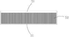
FIG. 3 is a top view structural diagram of the air-cooled frequency conversion all-in-one machine cooling fin of the present invention;
in the above figures: 1. a frequency converter; 11. a housing; 12. a side plate; 2. a motor; 21. a housing; 3. a connecting arm; 4. a heat dissipation channel; 5. a heat sink; 51. a panel; 52. a partition plate; 6. a hood; 61. an air inlet; 71. a first fan; 72. a second fan.
Detailed Description
The present invention is specifically described below by way of exemplary embodiments. It should be understood, however, that elements, structures and features of one embodiment may be beneficially incorporated in other embodiments without further recitation.
In the description of the present invention, it should be noted that the terms "inside", "outside", "upper", "lower", "front", "rear", and the like indicate orientations or positional relationships based on positional relationships shown in the drawings, and are only for convenience of description and simplification of description, but do not indicate or imply that the device or element referred to must have a specific orientation, be constructed and operated in a specific orientation, and thus, should not be construed as limiting the present invention. Furthermore, the terms "first," "second," and "third" are used for descriptive purposes only and are not to be construed as indicating or implying relative importance.
As shown in fig. 1 to 3, the utility model provides an air-cooled frequency conversion all-in-one machine, which comprises a frequency converter 1 and a motor 2.
The housing 11 of the frequency converter 1 is connected to the housing 21 of the electric motor 2 via a connecting arm 3, the connecting arm 3 separates the frequency converter 1 from the electric motor 2, and the space formed between the two serves as a heat dissipation channel 4.
A radiating fin 5 is arranged on the frequency converter 1, and the radiating fin 5 is positioned at the rear end of the shell 11.
The first fan 71 is mounted at the rear end of the main shaft of the motor 2, the hood 6 is mounted at the rear end of the housing 21 of the motor 2, and the first fan 71 is positioned in the hood 6.
The front end of the hood 6 is sleeved on the shell 21, and the rear end is provided with an air inlet 61.
The first fan 71 rotates along with the main shaft of the motor 2, sucks external air into the housing 6 through the air inlet 61, and blows the air after being concentrated in the housing 6 toward the motor 2 to dissipate heat of the motor 2.
The heat sink 5 is located above the hood 6, and includes two panels 51 arranged in parallel and at an interval, a partition plate 52 is arranged between the two panels 51, two ends of the partition plate 52 are respectively connected with the corresponding panels 51, and the partition plate 52 is arranged at intervals.
The two panels 51 and the two adjacent partitions 52 form a space through which air can flow, so that the air can pass through the inside of the heat sink 5, thereby taking away heat from the heat sink 5 and improving heat dissipation effect.
A panel 51 of the heat sink 5 is fixed on the side plate 12 at the rear side of the housing 11, so as to contact with the housing 11, thereby increasing the contact area, increasing the heat transfer speed, and rapidly transferring the heat on the frequency converter to the heat sink 5, thereby increasing the heat dissipation speed. In addition, the air flowing space is vertically arranged, so that high-temperature gas can easily rise and leave the air flowing space, and the heat dissipation in the radiating fins 5 is accelerated.
In order to accelerate the heat dissipation, the second fan 72 is installed on the heat sink 5 to send air to the heat sink 5, thereby accelerating the heat dissipation from the heat sink 5.
To further increase the heat dissipation speed, a second fan 72 is installed at the bottom end of the heat sink 5 to align with the opening of the air flowing space in the heat sink 5, and sends air into the heat sink 5 to increase the heat removal. In addition, the second fan 72 can suck air in the heat dissipation channel 4, thereby taking away heat in the heat dissipation channel 4 and improving the heat dissipation effect.
The first fan 71 sucks air at the rear side of the equipment to axially flow, one part of the air enters the hood 6 and blows towards the motor 2, the other part of the air flows along the outer wall of the hood 6 and flows into the heat dissipation channel 4, and heat dissipated to the heat dissipation channel 4 by the frequency converter 1 and the motor 2 is taken away, so that the inside of the equipment has high air circulation and the heat dissipation effect is enhanced.
The heat dissipation channel 4 separates the frequency converter 1 from the motor 2, weakens heat transfer between the frequency converter and the motor, and avoids the over-high temperature of the whole equipment.
The air sucked into the hood 6 by the first fan 71 flows out through the hook grooves provided in the housing 21 and flows along the outer wall of the motor 2, taking heat of the motor 2 away. Meanwhile, a part of air flowing along the outer wall of the motor 2 enters the heat dissipation channel 4 and takes away high-temperature air in the heat dissipation channel 4.
The height position of second fan 72 is higher than the bottom surface of casing 11, and the bottom surface of second fan 72 is higher than the casing 11 bottom surface promptly, prevents that second fan 72 from protruding downwards for the casing 11 bottom surface, and the air that flows out to heat dissipation channel 4 forms and blocks, makes the high temperature air in heat dissipation channel 4 can be more quick and smooth outflow, improves the radiating efficiency.
The top surface of the hood 6 is flush with the top surface of the housing 21, so that air flowing against the outer wall of the hood 6 can smoothly flow into the heat dissipation channel 4 and take away high-temperature air in the heat dissipation channel 4.
The IGBT module that converter 1 set up calorific capacity is great, and the IGBT module is installed on the curb plate 12 of casing 11 rear side, and the heat of production can directly transmit for fin 5 through curb plate 12, shortens the route of heat transfer for the radiating rate.
Claims (5)
1. An air-cooled frequency conversion all-in-one machine comprises a frequency converter (1) and a motor (2), and is characterized in that a shell (11) of the frequency converter (1) is connected with a shell (21) of the motor (2) through a connecting arm (3), and a heat dissipation channel (4) is arranged between the shell (11) and the shell (21);
the rear end of the shell (11) is provided with a radiating fin (5), and the rear end of the shell (21) is provided with a hood (6);
a first fan (71) is installed at the rear end of a main shaft of the motor (2), and the first fan (71) is positioned in the hood (6);
the front end of the hood (6) is sleeved on the shell (21), and the rear end of the hood is provided with an air inlet (61);
the radiating fins (5) comprise two panels (51) which are arranged in parallel at intervals, a partition plate (52) is arranged between the panels (51), two ends of the partition plate (52) are respectively connected with the corresponding panels (51), a plurality of partition plates (52) are arranged at intervals, and one panel (51) is fixed on a side plate (12) on the rear side of the shell (11);
and a second fan (72) is arranged at the bottom end of the radiating fin (5).
2. The air-cooled variable frequency all-in-one machine according to claim 1, wherein the height position of the second fan (72) is higher than the bottom surface of the housing (11).
3. An air-cooled frequency conversion all-in-one machine according to claim 1, characterized in that the top surface of the hood (6) is flush with the top surface of the housing (21).
4. An air-cooled frequency conversion all-in-one machine according to claim 1, wherein the cooling fins (5) are located above the hood (6).
5. An air-cooled frequency conversion all-in-one machine according to claim 1, characterized in that an IGBT module arranged on the frequency converter (1) is arranged on a side plate (12) at the rear side of the shell (11).
Priority Applications (1)
| Application Number | Priority Date | Filing Date | Title |
|---|---|---|---|
| CN201921654520.9U CN210273757U (en) | 2019-09-30 | 2019-09-30 | Air-cooled frequency conversion all-in-one machine |
Applications Claiming Priority (1)
| Application Number | Priority Date | Filing Date | Title |
|---|---|---|---|
| CN201921654520.9U CN210273757U (en) | 2019-09-30 | 2019-09-30 | Air-cooled frequency conversion all-in-one machine |
Publications (1)
| Publication Number | Publication Date |
|---|---|
| CN210273757U true CN210273757U (en) | 2020-04-07 |
Family
ID=70019941
Family Applications (1)
| Application Number | Title | Priority Date | Filing Date |
|---|---|---|---|
| CN201921654520.9U Active CN210273757U (en) | 2019-09-30 | 2019-09-30 | Air-cooled frequency conversion all-in-one machine |
Country Status (1)
| Country | Link |
|---|---|
| CN (1) | CN210273757U (en) |
Cited By (3)
| Publication number | Priority date | Publication date | Assignee | Title |
|---|---|---|---|---|
| CN112636516A (en) * | 2020-12-22 | 2021-04-09 | 华夏天信智能物联股份有限公司 | Mining frequency conversion speed regulation all-in-one |
| CN114793044A (en) * | 2021-01-25 | 2022-07-26 | 青岛中加特电气股份有限公司 | Safety-increasing explosion-proof type variable-frequency speed regulation all-in-one machine |
| CN116566110A (en) * | 2023-07-04 | 2023-08-08 | 中铁九局集团有限公司 | New energy mining truck driving motor with efficient heat dissipation structure |
-
2019
- 2019-09-30 CN CN201921654520.9U patent/CN210273757U/en active Active
Cited By (4)
| Publication number | Priority date | Publication date | Assignee | Title |
|---|---|---|---|---|
| CN112636516A (en) * | 2020-12-22 | 2021-04-09 | 华夏天信智能物联股份有限公司 | Mining frequency conversion speed regulation all-in-one |
| CN114793044A (en) * | 2021-01-25 | 2022-07-26 | 青岛中加特电气股份有限公司 | Safety-increasing explosion-proof type variable-frequency speed regulation all-in-one machine |
| CN116566110A (en) * | 2023-07-04 | 2023-08-08 | 中铁九局集团有限公司 | New energy mining truck driving motor with efficient heat dissipation structure |
| CN116566110B (en) * | 2023-07-04 | 2023-09-08 | 中铁九局集团有限公司 | New energy mining truck driving motor with efficient heat dissipation structure |
Similar Documents
| Publication | Publication Date | Title |
|---|---|---|
| US10462938B2 (en) | Inverter power cabinet | |
| CN210273758U (en) | Heat dissipation mechanism of frequency conversion all-in-one machine | |
| CN209895255U (en) | Wind-liquid mixed heat dissipation case | |
| CN210579876U (en) | Air cooling device of frequency conversion all-in-one machine | |
| CN211018559U (en) | Motor protection device | |
| CN110723009A (en) | A cooling charging pile for new energy vehicles | |
| CN222915880U (en) | Outdoor type frequency converter structure with independent air duct | |
| CN210555610U (en) | Unmanned aerial vehicle's heat radiation structure | |
| CN209962840U (en) | Novel cooling structure of dry-type transformer | |
| CN220768233U (en) | Heat radiation system for electric excavator and electric excavator | |
| CN218958364U (en) | Block terminal with cooling ventilation system | |
| CN209982235U (en) | Motor wind-guiding shell structure | |
| CN214366497U (en) | Starter with strong heat dissipation performance for excavator | |
| CN209840293U (en) | Outdoor unit and air conditioner with same | |
| CN210610186U (en) | Frequency conversion all-in-one radiator | |
| CN216216240U (en) | High-efficient heat radiation structure of motor | |
| CN210379024U (en) | A heat sink for semiconductor devices | |
| CN115149774A (en) | Frequency converter | |
| CN209744600U (en) | air conditioner suitable for hoisting equipment cockpit | |
| CN217720962U (en) | High-efficient radiating new energy automobile driving motor | |
| CN220383420U (en) | Heat radiation structure for ultra-large current driver and driver | |
| CN223566711U (en) | A lithium battery pack that facilitates heat dissipation | |
| CN218585759U (en) | Transformer capable of rapidly dissipating heat | |
| CN216477586U (en) | Fast engine cylinder body dispels heat | |
| CN217741955U (en) | High-efficient heat dissipation type LED drive power supply |
Legal Events
| Date | Code | Title | Description |
|---|---|---|---|
| GR01 | Patent grant | ||
| GR01 | Patent grant |