CN210262663U - Portable guardrail crossing device - Google Patents
Portable guardrail crossing device Download PDFInfo
- Publication number
- CN210262663U CN210262663U CN201920721586.9U CN201920721586U CN210262663U CN 210262663 U CN210262663 U CN 210262663U CN 201920721586 U CN201920721586 U CN 201920721586U CN 210262663 U CN210262663 U CN 210262663U
- Authority
- CN
- China
- Prior art keywords
- guardrail
- rotating shaft
- rod
- portable
- main
- Prior art date
- Legal status (The legal status is an assumption and is not a legal conclusion. Google has not performed a legal analysis and makes no representation as to the accuracy of the status listed.)
- Active
Links
- 238000000034 method Methods 0.000 abstract description 7
- 208000027418 Wounds and injury Diseases 0.000 abstract description 3
- 230000006378 damage Effects 0.000 abstract description 3
- 208000014674 injury Diseases 0.000 abstract description 3
- 230000001681 protective effect Effects 0.000 description 4
- 230000007613 environmental effect Effects 0.000 description 3
- 230000009286 beneficial effect Effects 0.000 description 1
- 238000009434 installation Methods 0.000 description 1
- 238000011084 recovery Methods 0.000 description 1
- 239000002689 soil Substances 0.000 description 1
Images


Landscapes
- Refuge Islands, Traffic Blockers, Or Guard Fence (AREA)
Abstract
The utility model provides a portable guardrail spanning device, main rail guard right-hand member have first pivot through bolt fixed mounting, and first pivot right side is rotated and is connected with vice rail guard, and main rail guard left side bottom all is equipped with the second pivot with vice rail guard right side bottom, and left and right sides second pivot bottom mounting is provided with the bracing piece. The portable guardrail spanning device can be unfolded very conveniently in the actual use process and immediately put into use, and can automatically and slowly recover the original fixed position after being kicked down slightly, so that the situation that a person with an improper use method causes hindrance and injury can be prevented.
Description
Technical Field
The utility model relates to a guardrail strideing across ware technical field specifically is a portable guardrail strideing across ware.
Background
The shared space of guardrail spanning device is too big in the past and carry inconveniently, and the installation connection structure is complicated relatively and brings inconvenient problem, and current guardrail spanning device is played the back and may trip the pedestrian, and need hold up repeatedly the guardrail spanning device who is played in the in-service use in-process, the big very inconvenient problem of work load.
SUMMERY OF THE UTILITY MODEL
The utility model aims at solving the technical problem that the shared space of guardrail spanning device is too big and carry inconvenient and need hold up repeatedly in the in-service use process, providing a portable guardrail spanning device.
In order to achieve the above objects, the present invention provides a portable guardrail crossing device, wherein a first rotating shaft is fixedly installed at the right end of a main guardrail through a bolt, an auxiliary guardrail is rotatably connected to the right side of the first rotating shaft, a second rotating shaft is respectively arranged at the left bottom end of the main guardrail and the right bottom end of the auxiliary guardrail, a support rod is fixedly arranged at the bottom end of the second rotating shaft at the left and right sides, the support rod comprises a fixing rod, a thread groove, a fixing block, a telescopic rod and a threaded rod, the bottom end of the second rotating shaft at the left and right sides is rotatably connected with the fixing rod, the inner wall of the fixing rod is fixedly provided with the thread groove, the fixing block is fixedly installed at the left and right sides of the bottom end of the inner wall of the fixing rod through the bolt, the, the fixed assembly comprises springs and fixed plates, the springs are fixedly mounted on the left side and the right side of the bottom end of the telescopic rod through bolts, the fixed plates are fixedly mounted on the bottom ends of the springs on the left side and the right side of the bottom end of the telescopic rod through bolts, and placing grooves are formed in openings in the lower surfaces of the main protective guard and the auxiliary protective guard.
Further, the main guard rail is rotatably connected with the auxiliary guard rail through a first rotating shaft, and the rotating angle of the first rotating shaft is 0-180 degrees.
Further, the threaded rod is meshed with the threaded groove and is in rotating connection with the threaded groove.
Furthermore, the left and right springs are consistent in length, and the fixing plates at the bottom ends of the left and right springs are located on the same horizontal line.
Furthermore, the main protective guard and the support rod, and the auxiliary protective guard and the support rod are rotatably connected through a second rotating shaft, and the rotating angle of the second rotating shaft is 0-110 degrees.
Furthermore, the distance between the fixed blocks is slightly smaller than two millimeters of the diameter of the section of the threaded rod.
The utility model provides a portable guardrail spanning device has following beneficial effect:
1. the utility model has the advantages of the user can expand fast and merge main rail guard and vice rail guard and insert in the standing groove, can expand very conveniently in the in-service use process, drop into the use immediately, make this kind of guardrail strider conveniently carry, can conveniently carry out the relative height of two spinal branch vaulting poles of positioning adjustment simultaneously according to the environmental requirement, have higher can plasticity and provide more selectivity on the aspect such as function to can satisfy multiple user's demand better.
2. Secondly, can carry out a good fixed with the telescopic link of guardrail spanning device through left and right sides spring, can automatic slow recovery original fixed position after the guardrail spanning device is kicked slightly, can prevent that improper person of application from causing the hindrance and the injury.
Drawings
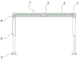
Fig. 1 is a schematic view of the overall structure of the present invention.
Fig. 2 is a schematic view of a partial section of the support rod of the present invention.
Fig. 3 is a schematic cross-sectional view of the fixing assembly of the present invention.
In FIGS. 1-3: the device comprises a main guard rail 1, a first rotating shaft 2, an auxiliary guard rail 3, a second rotating shaft 4, a supporting rod 5, a fixing rod 501, a thread groove 5011, a fixing block 5012, a telescopic rod 502, a threaded rod 5021, a fixing assembly 6, a spring 601, a fixing plate 603 and a placing groove 7.
Detailed Description
Based on the embodiments in the present invention, all other embodiments obtained by a person skilled in the art without creative work belong to the protection scope of the present invention.
Example (b):
referring to figures 1-3 of the drawings,
according to the portable guardrail crossing device provided by the embodiment, a first rotating shaft 2 is fixedly installed at the right end of a main guardrail 1 through a bolt, an auxiliary guardrail 3 is rotatably connected to the right side of the first rotating shaft 2, second rotating shafts 4 are respectively arranged at the left bottom end of the main guardrail 1 and the right bottom end of the auxiliary guardrail 3, and support rods 5 are fixedly arranged at the bottom ends of the second rotating shafts 4 at the left side and the right side;
the bracing piece 5 includes dead lever 501, thread groove 5011, fixed block 5012, telescopic link 502 and threaded rod 5021, 4 bottoms of left and right sides second pivot are all rotated and are connected with dead lever 501, the equal fixed thread groove 5011 that is provided with of dead lever 501 inner wall, there is fixed block 5012 fixed rod 501 inner wall bottom left and right sides all through bolt fixed mounting, the inside swing joint of dead lever 501 has telescopic link 502, there is threaded rod 5021 telescopic link 502 bottom through bolt fixed mounting, telescopic link 502 bottom mounting is provided with fixed subassembly 6, fixed subassembly 6 includes spring 601 and fixed plate 602, the telescopic link 502 bottom left and right sides all has spring 601 through bolt fixed mounting, there is fixed plate 602 left and right sides spring 601 bottom all through bolt fixed mounting, main rail guard 1 and the equal opening in vice rail guard 3 lower surface are.
Further, the main guard rail 1 and the auxiliary guard rail 3 are rotatably connected through a first rotating shaft 2, the rotating angle of the first rotating shaft 2 is 0-180 degrees, and a user can rapidly unfold and combine the main guard rail 1 and the auxiliary guard rail 3 and insert the main guard rail 1 and the auxiliary guard rail 3 into the placing groove 7 through the rotating angle of the first rotating shaft 2 is 0-180 degrees.
Further, the threaded rod 5021 is meshed with the threaded groove 5011 to be rotatably connected, so that the height between the fixing rod 501 and the telescopic rod 502 can be adjusted, the relative height of the two support rods 5 can be conveniently positioned and adjusted according to environmental requirements, and the phenomenon that the conventional guardrail spanning device can only work at one fixed height position is avoided.
Furthermore, the left and right springs 601 are identical in length, the fixing plates 602 at the bottom ends of the left and right springs 601 are located on the same horizontal line, and the telescopic rods 502 of the guardrail crossing device can be well fixed through the left and right springs 601.
Furthermore, the main guard rail 1 and the support rod 5, and the auxiliary guard rail 3 and the support rod 5 are rotatably connected through the second rotating shaft 4, and the rotating angle of the second rotating shaft 4 is 0-110 degrees, so that the auxiliary guard rail can be conveniently unfolded in the actual use process and can be immediately put into use.
Further, the distance between the fixing blocks 5012 is slightly smaller than the diameter of the cross section of the threaded rod 5021 by two millimeters, and the fixing blocks 5012 are used for keeping the distance between the fixing rod 501 and the telescopic rod 502.
Wherein, the fixing plate 602 can be embedded in the soil ground for positioning and fixing.
The working principle is as follows:
when the portable guardrail spanning device provided by the embodiment is used, firstly, the rotation angle of the first rotating shaft 2 is 0-180 degrees, so that a user can rapidly unfold and combine the main guardrail 1 and the auxiliary guardrail 3 and insert the main guardrail 1 and the auxiliary guardrail 3 into the placing groove 7, the main guardrail 1, the support rods 5 and the auxiliary guardrail 3 and the support rods 5 can be unfolded very conveniently through the second rotating shaft 4 and immediately put into use, meanwhile, the height between the fixed rod 501 and the telescopic rod 502 can be adjusted, the relative height of the two support rods 5 can be conveniently positioned and adjusted according to environmental requirements, the conventional guardrail spanning device can be prevented from working at a fixed height position, in the actual use process, the telescopic rod 502 of the guardrail spanning device can be well fixed through the left and right springs 601, and the original fixed position can be automatically and slowly recovered after the guardrail spanning device is slightly kicked down, can prevent the people with improper use from causing hindrance and injury.
Claims (6)
1. The portable guardrail crossing device is characterized in that a first rotating shaft (2) is fixedly mounted at the right end of a main guardrail (1) through bolts, an auxiliary guardrail (3) is rotatably connected at the right side of the first rotating shaft (2), second rotating shafts (4) are respectively arranged at the left side bottom end of the main guardrail (1) and the right side bottom end of the auxiliary guardrail (3), supporting rods (5) are fixedly arranged at the bottom ends of the second rotating shafts (4) at the left side and the right side, each supporting rod (5) comprises a fixing rod (501), a thread groove (5011), a fixing block (5012), a telescopic rod (502) and a threaded rod (5021), the bottom ends of the second rotating shafts (4) at the left side and the right side are respectively and rotatably connected with the fixing rod (501), the inner wall of each fixing rod (501) is fixedly provided with the thread groove (5011), and the, the utility model discloses a safety protection device, including dead lever (501), telescopic link (502) bottom have threaded rod (5021) through bolt fixed mounting, telescopic link (502) bottom mounting is provided with fixed subassembly (6), fixed subassembly (6) include spring (601) and fixed plate (602), both sides all have spring (601) through bolt fixed mounting about telescopic link (502) bottom, there are fixed plate (602) all through bolt fixed mounting in left and right sides spring (601) bottom, main rail guard (1) and vice rail guard (3) lower surface all open and are provided with standing groove (7).
2. The portable guardrail crossing device according to claim 1, wherein the main guardrail (1) and the auxiliary guardrail (3) are rotatably connected by a first rotating shaft (2), and the rotating angle of the first rotating shaft (2) is 0-180 °.
3. The portable guardrail crossing device of claim 1, wherein the threaded rod (5021) is in meshed rotational connection with the threaded slot (5011).
4. The portable guardrail crossing device of claim 1, wherein the left and right springs (601) have the same length, and the fixing plates (602) at the bottom ends of the left and right springs (601) are located on the same horizontal line.
5. The portable guardrail crossing device of claim 1, wherein the main guardrail (1) and the support bar (5) and the auxiliary guardrail (3) and the support bar (5) are rotatably connected by a second rotating shaft (4), and the rotating angle of the second rotating shaft (4) is 0-110 °.
6. The portable guardrail crossing device of claim 1, wherein the distance between the fixing blocks (5012) is slightly less than two millimeters of the cross-sectional diameter of the threaded rod (5021).
Priority Applications (1)
| Application Number | Priority Date | Filing Date | Title |
|---|---|---|---|
| CN201920721586.9U CN210262663U (en) | 2019-05-20 | 2019-05-20 | Portable guardrail crossing device |
Applications Claiming Priority (1)
| Application Number | Priority Date | Filing Date | Title |
|---|---|---|---|
| CN201920721586.9U CN210262663U (en) | 2019-05-20 | 2019-05-20 | Portable guardrail crossing device |
Publications (1)
| Publication Number | Publication Date |
|---|---|
| CN210262663U true CN210262663U (en) | 2020-04-07 |
Family
ID=70025476
Family Applications (1)
| Application Number | Title | Priority Date | Filing Date |
|---|---|---|---|
| CN201920721586.9U Active CN210262663U (en) | 2019-05-20 | 2019-05-20 | Portable guardrail crossing device |
Country Status (1)
| Country | Link |
|---|---|
| CN (1) | CN210262663U (en) |
-
2019
- 2019-05-20 CN CN201920721586.9U patent/CN210262663U/en active Active
Similar Documents
| Publication | Publication Date | Title |
|---|---|---|
| CN209837869U (en) | Construction guardrail | |
| CN209760977U (en) | Building construction safety device | |
| CN207092692U (en) | A kind of road construction safety barrier for building | |
| CN211499871U (en) | Anti-falling building construction support | |
| CN215443447U (en) | Foundation pit protective fence with windproof structure | |
| CN218757176U (en) | Municipal works median | |
| CN216921650U (en) | A novel safety device for municipal works | |
| CN215407841U (en) | Protective fence for perimeter security system | |
| CN213330351U (en) | Rail guard is used in building engineering construction | |
| CN216008044U (en) | Municipal administration is with rail guard that has can prolong mosaic structure | |
| CN208996487U (en) | A kind of building safety protective device | |
| CN210858232U (en) | Assembled rail guard is used in town road construction | |
| CN213329060U (en) | Highway landslide prevention mechanism | |
| CN211666415U (en) | Rail guard for building easily installs | |
| CN222414344U (en) | Building construction safety rail guard convenient to equipment | |
| CN209976158U (en) | Safety protective guard with adjustable angle | |
| CN210659518U (en) | Construction guardrail | |
| CN210482146U (en) | Breast board connection structure for bridge | |
| CN218324278U (en) | Engineering geological exploration safety protection rail | |
| CN221031850U (en) | Isolation guard rail for highway bridge maintenance | |
| CN221627718U (en) | Special fixture for laying and fixing dense mesh net | |
| CN216197094U (en) | Fence convenient to install for constructional engineering | |
| CN218346047U (en) | Buffering formula anticollision road guardrail | |
| CN216921611U (en) | Steel mould guardrail net device with crashproof | |
| CN222314787U (en) | A construction engineering guardrail |
Legal Events
| Date | Code | Title | Description |
|---|---|---|---|
| GR01 | Patent grant | ||
| GR01 | Patent grant |