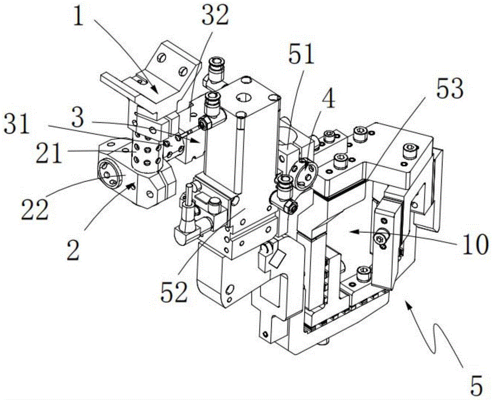
Multi-angle tongs connection structure
Technical Field
The utility model relates to an automobile manufacturing technical field specifically is a multi-angle tongs connection structure.
Background
With the continuous development of modern economy and the continuous improvement of the automation degree of industrial machinery, industrial robots equipped with specific grippers are widely popularized and widely applied to flow production lines, for example: to perform the operations of sorting, carrying and the like. However, there are a number of problems with the mechanical grippers currently used in the industry, such as: the product has the problems of complex structure, inaccurate positioning, high manufacturing cost, high power consumption, poor reliability, high noise, easy falling of a grabbed object and the like.
The utility model with the application number of CN201420799692.6 discloses a pneumatic three-jaw gripper device, which comprises a main body and three grippers which are connected with the main body and have the same structure, wherein three grippers are uniformly arranged, every two grippers form 120-degree included angles, a connecting rod is connected with a lug through a hinge pin, the gripper is connected with a movable plate through the hinge pin, the main body comprises a cylinder, a support, a guide shaft, three uniformly arranged angle frames, the lug, a connecting plate, a linear bearing, the movable plate and the like, the three angle frames are uniformly and fixedly connected on the support, every two grippers form 120-degree included angles, the three lugs are respectively and fixedly connected on the three angle frames, the three angle frames are fixedly connected with the connecting plate, the linear bearing is fixedly connected on the connecting plate, one end of the guide shaft is fixedly connected with the cylinder, the other end of the guide shaft is fixedly connected with the movable plate, the guide shaft is slidable in the linear bearing, and the link and the gripper are connected by the hinge pin.
However, above-mentioned utility model snatchs the door pattern at the practical application in-process and fixes, can not form the snatching of multi-angle, when needs turned angle, must change the tongs, increased the cost.
SUMMERY OF THE UTILITY MODEL
To above problem, the utility model provides a multi-angle tongs connection structure, it is through mutual rotatable setting between first connecting piece, second connecting piece and the first connecting pipe, can form the shape of snatching of multi-angle, has solved the technical problem that traditional tongs can only snatch an angle, has realized snatching of multi-angle, has reduced equipment cost.
In order to achieve the above object, the utility model provides a following technical scheme:
a multi-angle grip connection structure, comprising:
a first bracket;
the first connecting piece is rotatably arranged on the first support and is positioned below the first support;
the second connecting piece is rotatably arranged on the first connecting piece, is positioned on one side of the first connecting piece and is perpendicular to the first connecting piece;
one end of the first connecting pipe is rotatably arranged on the second connecting piece, is positioned on one side of the second connecting piece, is vertically arranged with the first connecting pipe and is vertically arranged with the first connecting piece; and
and the gripper mechanism is rotatably arranged at the other end of the first connecting pipe relative to the second connecting piece.
As an improvement, the first connecting member includes:
the second connecting pipe is rotatably arranged on the first bracket; and
and the first connecting seat is arranged at one end of the second connecting pipe and is positioned below the second connecting pipe, and the first connecting seat rotates synchronously along with the second connecting pipe.
As a refinement, the second connector comprises:
the third connecting pipe is rotatably arranged on the first connecting seat; and
and the second connecting seat is arranged at one end of the third connecting pipe and synchronously rotates along with the third connecting pipe.
As an improvement, the first connecting pipe is rotatably arranged on the second connecting seat.
As an improvement, the gripper mechanism comprises:
the second bracket is rotatably arranged on the first connecting pipe;
the driving assembly is arranged on one side of the second bracket along the length direction of the second bracket; and
the clamping assembly comprises a first clamping unit and a second clamping unit, and the first clamping unit is arranged in the middle of the other side of the second bracket relative to the driving assembly; the second clamping unit comprises a second base which is rotatably arranged at the lower part of the driving assembly, and the first clamping unit and the second clamping unit are combined to form a clamping area.
As an improvement, the drive assembly comprises:
a cylinder disposed at one side of the second bracket along a length direction of the second bracket, an
The connecting rod is driven by the cylinder to do telescopic motion and is positioned below the cylinder; and
and one end of the connecting block is connected with the end part of the connecting rod, and the other end of the connecting block is connected with the second base.
As an improvement, the first clamping unit includes:
the first base is arranged on one side of the second support;
the first clamping block is arranged on the first base and positioned below the first base;
the second clamping block is arranged on the first base and is positioned below the first base; and
the positioning block is arranged on the first base and is positioned on one side of the first clamping block.
As an improvement, the second clamping unit further includes:
the third clamping block is arranged on the second base and matched with the first clamping block; and
and the fourth clamping block is arranged on the second base and is matched with the second clamping block.
The beneficial effects of the utility model reside in that:
(1) the utility model can form a multi-angle grabbing shape through the mutual rotatable arrangement among the first connecting piece, the second connecting piece and the first connecting pipe, realizes multi-angle grabbing and reduces the equipment cost;
(2) the utility model positions the vehicle door through the positioning block and then clamps the vehicle door, thereby improving the stability of the vehicle door during working and improving the production quality;
(3) the utility model discloses a set up the packing ring between clamp splice and base for can have the buffering when carrying out the centre gripping to the door, in order to avoid causing the damage to the door in the centre gripping of door, simultaneously, can also reduce the buffer power of second centre gripping subassembly when rotating the centre gripping, prolong the life of tongs;
to sum up, the utility model has the advantages of simple structure, the multi-angle snatchs, improves stability, makes things convenient for the centre gripping, improves product quality.
Drawings
FIG. 1 is a schematic view of the overall structure of the present invention;
FIG. 2 is a front view of the overall structure of the present invention;
FIG. 3 is a top view of the overall structure of the present invention;
fig. 4 is a cross-sectional view of the drive assembly of the present invention;
Detailed Description
The technical solutions in the embodiments of the present invention will be described clearly and completely with reference to the accompanying drawings in the embodiments of the present invention, and it is obvious that the described embodiments are only some embodiments of the present invention, not all embodiments. Based on the embodiments in the present invention, all other embodiments obtained by a person skilled in the art without creative work belong to the protection scope of the present invention.
In the description of the present invention, it is to be understood that the terms "center", "longitudinal", "lateral", "length", "width", "thickness", "upper", "lower", "front", "rear", "left", "right", "vertical", "horizontal", "top", "bottom", "inner", "outer", "clockwise", "counterclockwise", and the like indicate orientations or positional relationships based on the orientations or positional relationships shown in the drawings, and are only for convenience of description and to simplify the description, but do not indicate or imply that the device or element referred to must have a particular orientation, be constructed and operated in a particular orientation, and therefore should not be construed as limiting the present invention.
Furthermore, the terms "first", "second" and "first" are used for descriptive purposes only and are not to be construed as indicating or implying relative importance or implicitly indicating the number of technical features indicated. Thus, a feature defined as "first" or "second" may explicitly or implicitly include one or more of that feature. In the description of the present invention, "a plurality" means two or more unless specifically limited otherwise.
Example (b):
as shown in fig. 1, 2 and 3, a multi-angle grip coupling structure includes:
a first support 1;
the first connecting piece 2 is rotatably arranged on the first support 1 and is positioned below the first support 1;
the second connecting piece 3 is rotatably arranged on the first connecting piece 2, is positioned on one side of the first connecting piece 2 and is perpendicular to the first connecting piece 2;
one end of the first connecting pipe 4 is rotatably arranged on the second connecting piece 3, is positioned on one side of the second connecting piece 3, is vertically arranged with the first connecting pipe 4, and is vertically arranged with the first connecting piece 2; and
and the gripper mechanism 5 is arranged at the other end of the first connecting pipe 4 in a rotatable manner relative to the second connecting piece 3.
Further, the first connecting member 2 includes:
the second connecting pipe 21 is rotatably arranged on the first bracket 1; and
the first connection seat 22 is disposed at one end of the second connection pipe 21, and the first connection seat 22 is located below the second connection pipe 21, and the first connection seat 22 rotates along with the second connection pipe 21.
Further, the second connector 3 includes:
a third connecting pipe 31, wherein the third connecting pipe 31 is rotatably arranged on the first connecting seat 22; and
a second connecting seat 32, the second connecting seat 32 being disposed at one end of the third connecting pipe 31, the second connecting seat 32 rotating synchronously with the third connecting pipe 31.
Wherein, the first connecting tube 4 is rotatably disposed on the second connecting seat 32.
Further, the gripper mechanism 5 includes:
a second bracket 51, wherein the second bracket 51 is rotatably arranged on the first connecting pipe 4;
a driving assembly 52, wherein the driving assembly 52 is disposed on one side of the second bracket 51 along the length direction of the second bracket 51; and
a clamping assembly 53, wherein the clamping assembly 53 comprises a first clamping unit 531 and a second clamping unit 532, and the first clamping unit 531 is arranged at the middle part of the other side of the second bracket 51 relative to the driving assembly 52; the second clamping unit 532 includes a second base 5321, the second base 5321 is rotatably disposed at a lower portion of the driving assembly 52, and the first clamping unit 531 and the second clamping unit 532 form a clamping area 10 in combination.
Further, as shown in fig. 4, the driving assembly 52 includes:
a cylinder 521, the cylinder 521 being disposed at one side of the second bracket 51 in a length direction of the second bracket 51, an
The connecting rod 522 is driven by the cylinder 521 to do telescopic motion and is positioned below the cylinder 521; and
and a connecting block 523, one end of which is connected to the end of the connecting rod 522, and the other end of which is connected to the second base 5321.
It should be noted that the connecting rod 522 and the connecting block 523 are externally shielded for protection.
Further, the first clamping unit 531 includes:
a first base 5311, the first base 5311 being disposed at one side of the second bracket 51;
a first clamping block 5312, the first clamping block 5312 being on the first base 5311 and located below the first base 5311;
the second clamping block 5313 is arranged on the first base 5311 and positioned below the first base 5311; and
the positioning block 5314 is disposed on the first base 5311 and located on one side of the first clamping block 5312.
Further, the second clamping unit 532 further includes:
the third clamping block 5322 is arranged on the second base 5321 and is matched with the first clamping block 5312; and
the fourth clamping block 5323 is disposed on the second base 5321, and the fourth clamping block 5323 is disposed in cooperation with the second clamping block 5313.
It should be noted that, in this embodiment, a gasket is disposed between the first clamping block and the first base, and between the third clamping block and the second base, and the gasket is disposed so that there is a buffer when the vehicle door is clamped, so as to prevent damage to the vehicle door during clamping of the vehicle door, and at the same time, the buffer force of the second clamping assembly during rotation clamping can be reduced, and the service life of the gripper is prolonged.
The working process is as follows:
the first connecting piece 2, the second connecting piece 3 and the first connecting pipe 4 are rotatably arranged mutually, so that a multi-angle grabbing shape can be formed, multi-angle grabbing is realized, and the equipment cost is reduced; the cylinder 521 pushes the connecting rod 5221 to move, the connecting block 5222 drives the second base 5321 to rotate, the first clamping block 5312 and the third clamping block 5322 are quota-matched and arranged, the second clamping block 5313 and the fourth clamping block 5323 are arranged in a matched mode, the vehicle door is clamped in the vertical direction, meanwhile, the vehicle door is positioned and fixed through the positioning block 5314, and the stability during processing is improved.
The above description is only exemplary of the present invention and should not be taken as limiting the scope of the present invention, as any modifications, equivalents, improvements and the like made within the spirit and principles of the present invention are intended to be included within the scope of the present invention.