CN210254336U - Porous processing equipment - Google Patents
Porous processing equipment Download PDFInfo
- Publication number
- CN210254336U CN210254336U CN201921213255.0U CN201921213255U CN210254336U CN 210254336 U CN210254336 U CN 210254336U CN 201921213255 U CN201921213255 U CN 201921213255U CN 210254336 U CN210254336 U CN 210254336U
- Authority
- CN
- China
- Prior art keywords
- guide rail
- rotary table
- base
- workbench
- drilling
- Prior art date
- Legal status (The legal status is an assumption and is not a legal conclusion. Google has not performed a legal analysis and makes no representation as to the accuracy of the status listed.)
- Expired - Fee Related
Links
- 238000003754 machining Methods 0.000 claims abstract description 12
- 239000004744 fabric Substances 0.000 claims description 8
- 238000004512 die casting Methods 0.000 claims 1
- 238000005553 drilling Methods 0.000 abstract description 15
Images

Landscapes
- Drilling And Boring (AREA)
- Perforating, Stamping-Out Or Severing By Means Other Than Cutting (AREA)
Abstract
The utility model provides a once press from both sides dress and can satisfy arbitrary position drilling, machining efficiency is high, is suitable for the porous processing equipment of multiple work piece drilling, has solved the porous processing that exists among the prior art and need press from both sides the dress many times and accomplish porous processing, and machining efficiency is low, only is suitable for the technical problem of single work piece processing. The utility model comprises a workbench, wherein a guide rail is arranged on the workbench, the guide rail comprises a transverse guide rail and a longitudinal guide rail, a base is arranged above the guide rail, a rotary table is arranged on the base, a driving device is arranged on one side of the rotary table, the driving device controls the rotary table to rotate, and at least one fixing part for fixing a mould is arranged on the rotary table; and cutter seats are also arranged on two sides of the workbench. The utility model can meet the drilling requirements in different directions, and is suitable for drilling workpieces with different specifications; the drilling machining efficiency is high; easy control of the depth of feed.
Description
Technical Field
The utility model relates to a processing equipment especially relates to a porous processing equipment.
Background
Some workpieces need to be drilled in multiple directions during machining, and particularly, certain workpieces with specific radians are inconvenient to drill. The existing porous processing equipment needs to clamp for many times, manually adjusts the workpiece to drill, and has low processing efficiency. Further, since the manual adjustment certainly causes deviation in the depth of cut during drilling and the yield of workpiece machining is lowered, an apparatus capable of performing multi-hole machining by clamping at one time is required to solve this problem.
Disclosure of Invention
The utility model provides a once press from both sides dress and can satisfy arbitrary position drilling, machining efficiency is high, is suitable for the porous processing equipment of multiple work piece drilling, has solved the porous processing that exists among the prior art and need press from both sides the dress many times and accomplish porous processing, and machining efficiency is low, only is suitable for the technical problem of single work piece processing.
The above problems of the present invention are solved by the following technical solutions: a porous processing device comprises a workbench, wherein a guide rail is arranged on the workbench and comprises a transverse guide rail and a longitudinal guide rail, a base is arranged above the guide rail, a rotary table is arranged on the base, a driving device is arranged on one side of the rotary table and controls the rotary table to rotate, and at least one fixing piece for fixing a mold is arranged on the rotary table; and cutter seats are also arranged on two sides of the workbench. The guide rails are arranged above the workbench, and the two guide rails are respectively a transverse guide rail and a longitudinal guide rail, so that the base can freely move on an x axis and a y axis. The base is provided with a rotary table, a worm wheel and a worm are arranged below the rotary table, and the driving device drives the rotary table to rotate by driving the worm wheel and the worm. The specifications of the workpieces to be machined are different, the rotary table is provided with a plurality of fixing pieces, and the workpieces of various specifications can be fixed on the rotary table for drilling according to the specifications of the workpieces and by matching with different fixing pieces. The two sides of the workbench are provided with cutter seats, and cutters for processing workpieces are arranged on the cutter seats. The rotary table can rotate by 360 degrees, and the drilling of a plurality of action holes in different directions on the workpiece is realized through the rotation of the rotary table, so that the aims of clamping at one time and processing the plurality of action holes are fulfilled.
Preferably, the rotary table is circular and is fixed on the upper side surface of the base; the fixing piece is a through groove and is positioned on the upper side face of the rotary table. The rotary table is fixed on the upper side surface of the base, the base can freely move on the x axis and the y axis, therefore, the rotary table can also freely move on the x axis and the y axis, and the rotary table can rotate 360 degrees, therefore, action holes in all directions can be processed. The fixing piece is a through groove, and the die can be clamped into the through groove from the side edge of the rotary table to fix the workpiece on the rotary table.
Preferably, the number of the through grooves is three, and the width of each through groove is larger than that of the clamping piece below the mold. The rotary table is provided with three through grooves, one through groove is arranged on the central line of the rotary table, the other two through grooves are symmetrically distributed on two sides, and the three through grooves are parallel to each other. Because the specifications of the workpieces are inconsistent, the three through grooves can meet the fixation of the workpieces with different specifications, so that the rotary table is not limited to the drilling processing of the workpieces with single specification.
Preferably, the transverse guide rail is fixed on the workbench, a guide rail fixing seat is arranged above the transverse guide rail, the longitudinal guide rail is fixed on the guide rail fixing seat, and the base is located above the longitudinal guide rail. The transverse guide rail and the longitudinal guide rail are vertically distributed, the transverse guide rail is fixed on the workbench, a guide rail fixing seat is arranged above the transverse guide rail, the longitudinal guide rail is fixed on the guide rail fixing seat, and the base is arranged on the longitudinal guide rail. Such a rail arrangement allows the base to move freely in the x and y axes.
Preferably, telescopic dustproof cloth is arranged above the transverse guide rail and the longitudinal guide rail. The piece that dustproof cloth can avoid drilling to produce can not drop on the guide rail, ensures the normal operating of guide rail. The dustproof cloth is telescopic, and the stretching requirement on the dustproof cloth when the base moves can be met.
Preferably, at least four cutter seats are arranged on two sides of the workbench, and the cutter seats are positioned at two ends of the transverse guide rail. The cutter seats are arranged at two ends of the transverse guide rail, and two cutter seats are arranged on the workbench at each side. The base moves on the x axis and the y axis, the feed depth of the cutter can be controlled, and the same action hole drilling depth is realized. The rotary table can rotate 360 degrees, and the cutter can drill holes in any direction on the workpiece.
Preferably, the driving device is a motor, and the motor is fixed on the base. The motor is adopted as a driving device, so that the connection is convenient and the operation is simple.
Preferably, a sensor is arranged on one side of the rotary table and fixed on the base. When the motor breaks down, operating personnel can not discover the motor fault fast, so the normal rotation of the rotary table can be influenced. The sensor acts as a protection device and receives a signal every revolution of the turntable, and when the sensor does not receive a signal, it indicates that the turntable is out of order.
Therefore, the utility model has the advantages of as follows: the guide rails are divided into transverse guide rails and longitudinal guide rails, and the base can move on the x axis and the y axis, so that the cutting depth is easier to control while the processing is convenient; the rotary table can rotate 360 degrees, so that the drilling requirements of different directions on the workpiece are met; the fixing piece on the rotary table is a through groove, and a workpiece is clamped into the through groove from the side surface of the rotary table for fixing, so that the fixing mode is simple; three through grooves are formed in the rotary table, so that the fixation of workpieces of different specifications can be met; the multi-hole machining can be completed by one-time clamping, and the machining efficiency is high; the driving device is a motor, so that the operation is simple; the sensor is arranged, so that the normal operation of the rotary table can be ensured.
Drawings
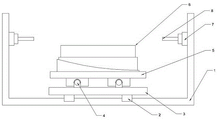
Fig. 1 is a side view of the multi-hole processing apparatus of the present invention.
Fig. 2 is a top view of the multi-hole processing apparatus of the present invention.
Description of the drawings: 1-workbench, 2-transverse guide rail, 3-guide rail fixing seat, 4-longitudinal guide rail, 5-base, 6-rotary table, 7-cutter seat, 8-drill bit, 9-through groove, 10-motor, 11-sensor and 12-dustproof cloth.
Detailed Description
The technical solution of the present invention is further specifically described below by way of examples and with reference to the accompanying drawings.
Example (b): a multi-hole processing apparatus as shown in FIGS. 1-2. The workbench 1 is U-shaped, a transverse guide rail 2 is arranged on the horizontal plane of the workbench 1, and two ends of the transverse guide rail 2 are fixed on the vertical plane of the workbench 1. Above the transverse guide rail 2 is a guide rail fixing seat 3, and the guide rail fixing seat 3 moves on the transverse guide rail 2. The guide rail fixing seat 3 is provided with a longitudinal guide rail 4, the base 5 is arranged above the longitudinal guide rail 4, the base 5 moves on the longitudinal guide rail, and the guide rail fixing seat 3 drives the base 5 to move on the transverse guide rail 2. All having laid dustproof cloth 12 on transverse guide 2 and longitudinal rail 4, dustproof cloth 12's width and guide rail width phase-match can cover the guide rail completely, guarantee that the piece that drilling produced can not drop on the guide rail, guarantee the normal operating of guide rail. The base 5 is provided with a rotary table 6, the upper side surface of the rotary table 6 is provided with three through grooves 9, one through groove 9 is positioned on the central line of the rotary table 6, the other two through grooves 9 are symmetrically distributed on two sides of the central line of the rotary table, and the three through grooves 9 are parallel to each other. The mould is clamped into the through groove 9 from the side surface of the rotary table 6, and the width of the through groove 9 is larger than that of the clamping piece below the mould. The three through grooves 9 can meet the fixation of workpieces with different specifications, so that the rotary table 6 can be suitable for processing workpieces with various specifications. The rotary table 6 is driven to rotate by a motor 10 fixed on the working table 1, a sensor 11 is arranged at the left side of the motor 10, and the sensor 11 is used for ensuring the normal operation of the rotary table 6. Two cutter seats 7 are fixed on the vertical surfaces of two sides of the workbench 1, and drill bits 8 are arranged on the cutter seats 7. The workpiece on the rotary table 6 moves on the x axis and the y axis along with the base 5, the rotary table 6 can rotate, and the drill bit 8 can drill holes on any position of the workpiece.
When the tool is used, a workpiece is fixed on the die, and the die is clamped into the through groove 9 from the side surface of the rotary table 6. After the workpiece is fixed, the position of the workpiece needing to be drilled is adjusted to a proper position through the rotation of the rotary table 6 according to the position of the drill bit 8. The control base 5 moves on the longitudinal guide rails 4 to align the position to be drilled with the drill bit 8, and the control base 5 moves on the transverse guide rails 2 to drill.
Claims (8)
1. A porous processing equipment, contains the workstation, its characterized in that: the die casting machine is characterized in that a guide rail is arranged on the workbench and comprises a transverse guide rail and a longitudinal guide rail, a base is arranged above the guide rail, a rotary table is arranged on the base, a driving device is arranged on one side of the rotary table and controls the rotary table to rotate, and at least one fixing piece for fixing a die is arranged on the rotary table; and cutter seats are also arranged on two sides of the workbench.
2. A multi-hole machining apparatus according to claim 1, characterized in that: the rotary table is circular and is fixed on the upper side surface of the base; the fixing piece is a through groove and is positioned on the upper side face of the rotary table.
3. A multi-hole machining apparatus according to claim 2, characterized in that: the number of the through grooves is three, and the width of each through groove is larger than that of the clamping piece below the mold.
4. A multi-hole processing apparatus according to claim 1, 2 or 3, wherein: the transverse guide rail is fixed on the workbench, a guide rail fixing seat is arranged above the transverse guide rail, the longitudinal guide rail is fixed on the guide rail fixing seat, and the base is located above the longitudinal guide rail.
5. A multi-hole processing apparatus according to claim 1, 2 or 3, wherein: and telescopic dustproof cloth is arranged above the transverse guide rail and the longitudinal guide rail.
6. A multi-hole processing apparatus according to claim 1, 2 or 3, wherein: two sides of the workbench are at least provided with two cutter seats, and the cutter seats are positioned at two ends of the transverse guide rail.
7. A multi-hole processing apparatus according to claim 1, 2 or 3, wherein: the driving device is a motor, and the motor is fixed on the base.
8. A multi-hole processing apparatus according to claim 1, 2 or 3, wherein: and a sensor is arranged on one side of the rotary table and is fixed on the base.
Priority Applications (1)
| Application Number | Priority Date | Filing Date | Title |
|---|---|---|---|
| CN201921213255.0U CN210254336U (en) | 2019-07-30 | 2019-07-30 | Porous processing equipment |
Applications Claiming Priority (1)
| Application Number | Priority Date | Filing Date | Title |
|---|---|---|---|
| CN201921213255.0U CN210254336U (en) | 2019-07-30 | 2019-07-30 | Porous processing equipment |
Publications (1)
| Publication Number | Publication Date |
|---|---|
| CN210254336U true CN210254336U (en) | 2020-04-07 |
Family
ID=70015063
Family Applications (1)
| Application Number | Title | Priority Date | Filing Date |
|---|---|---|---|
| CN201921213255.0U Expired - Fee Related CN210254336U (en) | 2019-07-30 | 2019-07-30 | Porous processing equipment |
Country Status (1)
| Country | Link |
|---|---|
| CN (1) | CN210254336U (en) |
Cited By (2)
| Publication number | Priority date | Publication date | Assignee | Title |
|---|---|---|---|---|
| CN114309766A (en) * | 2022-03-04 | 2022-04-12 | 南京莱迪新能源科技有限公司 | Linear sensing detection type preliminary disassembling device and method for lithium battery |
| CN120941261A (en) * | 2025-10-16 | 2025-11-14 | 沈阳和研科技股份有限公司 | Rotary positioning system, control method of rotary positioning system and grinding equipment |
-
2019
- 2019-07-30 CN CN201921213255.0U patent/CN210254336U/en not_active Expired - Fee Related
Cited By (3)
| Publication number | Priority date | Publication date | Assignee | Title |
|---|---|---|---|---|
| CN114309766A (en) * | 2022-03-04 | 2022-04-12 | 南京莱迪新能源科技有限公司 | Linear sensing detection type preliminary disassembling device and method for lithium battery |
| CN114309766B (en) * | 2022-03-04 | 2022-06-07 | 南京莱迪新能源科技有限公司 | A lithium battery linear sensing detection type preliminary dismantling device and method |
| CN120941261A (en) * | 2025-10-16 | 2025-11-14 | 沈阳和研科技股份有限公司 | Rotary positioning system, control method of rotary positioning system and grinding equipment |
Similar Documents
| Publication | Publication Date | Title |
|---|---|---|
| US4738170A (en) | Machine tool | |
| CN103286831B (en) | Numerical control woodworking lathe and carving multifunctional all-in-one machine | |
| CN105834750B (en) | A kind of numerical control rolling linear guide rig | |
| CN106514437A (en) | Double-spindle numerical-control machine tool | |
| CN201815729U (en) | Cardan universal joint groove milling device | |
| CN217702276U (en) | Gear shaft cover processing equipment | |
| CN210209379U (en) | Turning and drilling integrated efficient numerical control lathe | |
| CN104842223A (en) | Gantry type digital controlled lathe | |
| CN205394001U (en) | Digit control machine tool is used in work piece processing | |
| CN220480847U (en) | Double-spindle turning and milling composite lathe for synchronously machining front and back surfaces | |
| CN221621467U (en) | Workbench for machine tool machining | |
| CN221249390U (en) | Bidirectional punching device and numerical control equipment | |
| CN209349856U (en) | A kind of multistation blower processing unit (plant) | |
| CN207358208U (en) | It is a kind of can two-sided processing clamping apparatus for lathe | |
| CN208696355U (en) | A kind of four axis drilling machine of numerical control gantry | |
| CN207723548U (en) | A working positioning device for CNC milling machine with tool changer | |
| CN216462955U (en) | Well club angle sign indicating number automatic processing equipment | |
| CN104816164A (en) | Sectional material processing machine | |
| CN206373708U (en) | Double spindle numerical control machine tools | |
| CN214489577U (en) | Double-station numerical control drilling machine | |
| CN211072561U (en) | Drilling and notching machine for conductive bobbin | |
| CN211708828U (en) | Machining center | |
| CN223776106U (en) | Copper bar heat shrinkage pipe faying face cutting machine | |
| CN223889587U (en) | A twin-spindle CNC lathe with a tool post mounting structure | |
| CN221560488U (en) | Double-headstock cutting device |
Legal Events
| Date | Code | Title | Description |
|---|---|---|---|
| GR01 | Patent grant | ||
| GR01 | Patent grant | ||
| CF01 | Termination of patent right due to non-payment of annual fee |
Granted publication date: 20200407 |
|
| CF01 | Termination of patent right due to non-payment of annual fee |