CN210247522U - Organic fertilizer application is with spilling material device - Google Patents
Organic fertilizer application is with spilling material device Download PDFInfo
- Publication number
- CN210247522U CN210247522U CN201920962375.4U CN201920962375U CN210247522U CN 210247522 U CN210247522 U CN 210247522U CN 201920962375 U CN201920962375 U CN 201920962375U CN 210247522 U CN210247522 U CN 210247522U
- Authority
- CN
- China
- Prior art keywords
- pivot
- bevel gear
- fixed mounting
- organic fertilizer
- bearing
- Prior art date
- Legal status (The legal status is an assumption and is not a legal conclusion. Google has not performed a legal analysis and makes no representation as to the accuracy of the status listed.)
- Expired - Fee Related
Links
- 239000000463 material Substances 0.000 title claims abstract description 38
- 239000003895 organic fertilizer Substances 0.000 title claims abstract description 30
- 238000003756 stirring Methods 0.000 claims abstract description 16
- 238000009434 installation Methods 0.000 claims description 8
- 238000007599 discharging Methods 0.000 claims description 7
- 239000013590 bulk material Substances 0.000 claims description 6
- 238000012856 packing Methods 0.000 claims description 5
- 239000003337 fertilizer Substances 0.000 description 11
- 235000015097 nutrients Nutrition 0.000 description 6
- 239000002689 soil Substances 0.000 description 6
- 230000009471 action Effects 0.000 description 5
- 210000003608 fece Anatomy 0.000 description 5
- 239000010871 livestock manure Substances 0.000 description 5
- 238000000034 method Methods 0.000 description 5
- 238000005507 spraying Methods 0.000 description 4
- 230000004720 fertilization Effects 0.000 description 3
- 230000008569 process Effects 0.000 description 3
- 239000007921 spray Substances 0.000 description 2
- 238000003466 welding Methods 0.000 description 2
- OKTJSMMVPCPJKN-UHFFFAOYSA-N Carbon Chemical compound [C] OKTJSMMVPCPJKN-UHFFFAOYSA-N 0.000 description 1
- 230000004075 alteration Effects 0.000 description 1
- 230000009286 beneficial effect Effects 0.000 description 1
- 229910052799 carbon Inorganic materials 0.000 description 1
- 239000002361 compost Substances 0.000 description 1
- 150000001875 compounds Chemical class 0.000 description 1
- 230000035558 fertility Effects 0.000 description 1
- 239000007789 gas Substances 0.000 description 1
- 238000004519 manufacturing process Methods 0.000 description 1
- 244000005700 microbiome Species 0.000 description 1
- 238000012986 modification Methods 0.000 description 1
- 230000004048 modification Effects 0.000 description 1
- 235000016709 nutrition Nutrition 0.000 description 1
- 230000035764 nutrition Effects 0.000 description 1
- 239000000126 substance Substances 0.000 description 1
- 238000006467 substitution reaction Methods 0.000 description 1
- 230000001502 supplementing effect Effects 0.000 description 1
- XLYOFNOQVPJJNP-UHFFFAOYSA-N water Substances O XLYOFNOQVPJJNP-UHFFFAOYSA-N 0.000 description 1
Images


Landscapes
- Fertilizing (AREA)
Abstract
The utility model discloses an organic fertilizer application is with spilling material device, including conveying pipeline, workbin and mount table in advance, the conveying pipeline fixed mounting be in the top of mount table, workbin fixed mounting is in advance in the top of conveying pipeline, just the intermediate position department of workbin bottom has seted up the opening in advance, the workbin in advance passes through the opening with the conveying pipeline communicates mutually, the one end of conveying pipeline is provided with driving motor, driving motor's bottom is provided with motor base, driving motor passes through motor base fixed mounting be in the top of mount table, the intermediate position at workbin top is provided with the bearing in advance, the inside of workbin in advance passes through bearing movable mounting has the (mixing) shaft, the surface of (mixing) shaft is provided with helical stirring blade. The utility model discloses a set up a series of structures and make this device have spill material fast and the even characteristics of bulk cargo.
Description
Technical Field
The utility model relates to an organic fertilizer technical field specifically is an organic fertilizer application is with spilling material device.
Background
The organic fertilizer is also called 'farmyard manure'. Organic fertilizers are all produced by using organic substances (compounds containing carbon elements) as fertilizers. Including human excrement, manure, compost, green manure, cake manure, biogas manure, and the like. Has the characteristics of multiple varieties, wide sources, long fertilizer efficiency and the like. The organic fertilizer contains many nutrient elements in organic state, and is difficult to be directly utilized by crops, and through the action of microorganisms, various nutrient elements are slowly released, and the nutrients are continuously supplied to the crops. The application of the organic fertilizer can improve the soil structure, effectively coordinate water, fertilizer, gas and heat in the soil, and improve the soil fertility and the land productivity.
In the agricultural planting production process, when nutrition required by crop growth and development cannot be provided in soil, the action of artificially supplementing nutrient elements to crops is called fertilization, soil nutrients are increased, and the soil nutrients can be increased no matter organic fertilizers or inorganic fertilizers are applied, but the sprinkling speed of the existing sprinkling device for fertilization is low in the using process, the sprinkling range is small, and the sprinkling is not uniform enough, so that the problem is solved by the sprinkling device for organic fertilizer fertilization.
SUMMERY OF THE UTILITY MODEL
An object of the utility model is to provide an organic fertilizer application is with spilling material device to solve the problem that proposes among the above-mentioned background art.
In order to achieve the above object, the utility model provides a following technical scheme: a material sprinkling device for organic fertilizer application comprises a conveying pipe, a pre-feeding box and an installation platform, wherein the conveying pipe is fixedly installed at the top of the installation platform, the pre-feeding box is fixedly installed at the top of the conveying pipe, an opening is formed in the middle position of the bottom of the pre-feeding box, the pre-feeding box is communicated with the conveying pipe through the opening, a driving motor is arranged at one end of the conveying pipe, a motor base is arranged at the bottom of the driving motor, the driving motor is fixedly installed at the top of the installation platform through the motor base, a bearing is arranged at the middle position of the top of the pre-feeding box, a stirring shaft is movably installed in the pre-feeding box through the bearing, spiral stirring blades are arranged on the surface of the stirring shaft, a fourth cone angle gear is fixedly installed at the top end of the stirring shaft, installation rods are welded at two ends of the top of the, the bearings are arranged at the top ends of the two mounting rods, a first rotating shaft is movably mounted at the top ends of the two mounting rods through the bearings, a third bevel gear is fixedly mounted at the middle position of the surface of the first rotating shaft, a driven sprocket is fixedly mounted at one end of the first rotating shaft, a second rotating shaft is arranged at the output end of the driving motor, a driving sprocket is fixedly mounted at one end of the second rotating shaft, a chain is arranged on the outer side of the driving sprocket in a surrounding manner, the driving sprocket is connected with the driven sprocket through the chain, a first bevel gear is fixedly mounted at the other end of the second rotating shaft, the bearings are arranged at the top end of one side of the conveying pipe, a third rotating shaft is movably mounted at one end of the inside of the conveying pipe through the bearings, a discharging pipe is fixedly mounted at one end of the bottom of the conveying pipe, and the third rotating shaft is located inside, and the surface of the third rotating shaft is sleeved with a second bevel gear, the bottom end of the discharging pipe is fixedly provided with a material sprinkling head, the inner part of the material sprinkling head is movably provided with a material scattering disk, and the material scattering disk is fixed with the bottom end of the third rotating shaft through welding.
Preferably, the third bevel gear is located on one side of the fourth bevel gear, and the third bevel gear is intermeshed with the fourth bevel gear, the first bevel gear is located on one side of the second bevel gear, and the second bevel gear is intermeshed with the first bevel gear.
Preferably, both ends of the bottom of the pre-feeding box are provided with landslides.
Preferably, one end of the top of the prediction box is fixedly provided with a feeding pipe, and the top end of the feeding pipe is fixedly provided with an expanded feeding head.
Preferably, a plurality of bulk material holes are formed in the bulk material tray.
Preferably, the surface of the second rotating shaft is provided with a packing auger.
Compared with the prior art, the beneficial effects of the utility model are that: the utility model has the advantages of being scientific and reasonable in structure, convenient and safe in utilization, through controlling driving motor, make the second pivot rotate, driving sprocket is installed to one end of second pivot, and connect through the chain between driving sprocket and the driven sprocket, thereby make the first pivot rotate, the intermediate position department on first pivot surface cup joints and installs third bevel gear, third bevel gear and fourth bevel gear intermeshing, thereby make the (mixing) shaft rotate, because be provided with spiral stirring vane on the surface of (mixing) shaft, thereby make the organic fertilizer in the preliminary work case inside can carry out the even stirring before spraying, make the later stage when spraying fertilizer effectual, and when the second pivot rotates, make the auger rotate, thereby make the organic fertilizer can carry to the mouth of pipe department of discharging pipe, thereby accelerate the conveying speed of organic fertilizer, and through fixedly installing first bevel gear at the one end of second pivot, first cone angle gear and second cone angle gear intermeshing for the second pivot drives the third pivot when rotating and rotates, thereby makes the bulk cargo dish rotate, owing to a plurality of bulk cargo hole has been seted up in the inside of bulk cargo dish, thereby rotates through the bulk cargo dish when making to spray, can make the organic fertilizer ejection of compact when the ejection of compact even, and the scope that effectual increase fertilizer sprayed.
Drawings
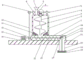
Fig. 1 is a schematic structural view of the whole of the present invention;
FIG. 2 is a schematic structural view of the bulk material tray of the present invention;
fig. 3 is an enlarged view of a portion a in fig. 1 according to the present invention.
In the figure: 1. a delivery pipe; 2. a pre-feeding box; 3. a helical mixing blade; 4. a stirring shaft; 5. a first rotating shaft; 6. a feed tube; 7. a wide-range feeding head; 8. mounting a rod; 9. a driven sprocket; 10. a chain; 11. landslide; 12. a drive sprocket; 13. a drive motor; 14. a motor base; 15. a packing auger; 16. a second rotating shaft; 17. a first bevel gear; 18. a material sprinkling head; 19. a bulk material tray; 20. a discharge pipe; 21. an installation table; 22. a third rotating shaft; 23. a second bevel gear; 24. a bearing; 25 bulk holes; 26. a third bevel gear; 27. a fourth bevel gear.
Detailed Description
The technical solutions in the embodiments of the present invention will be described clearly and completely with reference to the accompanying drawings in the embodiments of the present invention, and it is obvious that the described embodiments are only some embodiments of the present invention, not all embodiments. Based on the embodiments in the present invention, all other embodiments obtained by a person skilled in the art without creative work belong to the protection scope of the present invention.
Referring to fig. 1-3, the present invention provides a technical solution: a technical scheme of a material sprinkling device for organic fertilizer application comprises a material conveying pipe 1, a material forecasting box 2 and a mounting platform 21, wherein the material conveying pipe 1 is fixedly arranged at the top of the mounting platform 21, the material forecasting box 2 is fixedly arranged at the top of the material conveying pipe 1, an opening is formed in the middle position of the bottom of the material forecasting box 2, the material forecasting box 2 is communicated with the material conveying pipe 1 through the opening, a driving motor 13 is arranged at one end of the material conveying pipe 1, a motor base 14 is arranged at the bottom of the driving motor 13, the driving motor 13 is fixedly arranged at the top of the mounting platform 21 through the motor base 14, a bearing 24 is arranged at the middle position of the top of the material forecasting box 2, a stirring shaft 4 is movably arranged in the material forecasting box 2 through the bearing 24, a spiral stirring blade 3 is arranged on the surface of the stirring shaft 4, a fourth cone angle gear 27 is fixedly arranged at the, the top ends of the two mounting rods 8 are respectively provided with a bearing 24, the top ends of the two mounting rods 8 are movably provided with a first rotating shaft 5 through the bearing 24, the middle position of the surface of the first rotating shaft 5 is fixedly provided with a third bevel gear 26, one end of the first rotating shaft 5 is fixedly provided with a driven sprocket 9, the output end of a driving motor 13 is provided with a second rotating shaft 16, one end of the second rotating shaft 16 is fixedly provided with a driving sprocket 12, the outer side of the driving sprocket 12 is annularly provided with a chain 10, the driving sprocket 12 is connected with the driven sprocket 9 through the chain 10, the other end of the second rotating shaft 16 is fixedly provided with a first bevel gear 17, the top end of one side of the conveying pipe 1 is provided with the bearing 24, one end inside the conveying pipe 1 is movably provided with a third rotating shaft 22 through the bearing 24, one end of the bottom of the conveying pipe 1 is fixedly provided with a, and the surface of the third rotating shaft 22 is sleeved with a second bevel gear 23, the bottom end of the discharge pipe 20 is fixedly provided with a material sprinkling head 18, the interior of the material sprinkling head 18 is movably provided with a material scattering disk 19, and the material scattering disk 19 is fixed with the bottom end of the third rotating shaft 22 by welding.
Preferably, the third bevel gear 26 is located on one side of the fourth bevel gear 27, and the third bevel gear 26 is intermeshed with the fourth bevel gear 27, the first bevel gear 17 is located on one side of the second bevel gear 23, and the second bevel gear 23 is intermeshed with the first bevel gear 17.
Preferably, the two ends of the bottom of the pre-feeding box 2 are provided with landslides 11, so that the organic fertilizer in the pre-feeding box 2 can fall into the conveying pipe 1.
Preferably, a feeding pipe 6 is fixedly installed at one end of the top of the prediction box 2, and an expanded feeding head 7 is fixedly installed at the top end of the feeding pipe 6, so that organic fertilizer can be conveniently added into the prediction box 2.
Preferably, a plurality of bulk cargo hole 25 has been seted up to bulk cargo dish 19's inside, rotates through bulk cargo dish 19, can make the organic fertilizer ejection of compact when the ejection of compact even, and the scope that effectual increase fertilizer sprayed.
Preferably, the packing auger 15 is arranged on the surface of the second rotating shaft 16, and the packing auger 15 rotates, so that the organic fertilizer can be conveyed to the pipe orifice of the discharge pipe 20.
The working principle is as follows: the utility model discloses a through control driving motor 13, make second pivot 16 rotate, drive sprocket 12 is installed to the one end of second pivot 16, and connect through chain 10 between drive sprocket 12 and the driven sprocket 9, thereby make first pivot 5 rotate, the intermediate position department on first pivot 5 surface cup joints and installs third bevel gear 26, third bevel gear 26 and fourth bevel gear 27 intermeshing, thereby make (mixing) shaft 4 rotate, because be provided with spiral stirring vane 3 on the surface of (mixing) shaft 4, thereby make the organic fertilizer in the preliminary work case 2 inside can carry out even stirring before spraying, make the later stage at the effectual of fertilizer when spraying, and when second pivot 16 rotates, make auger 15 rotate, thereby make the organic fertilizer can carry to the pipe mouth department of discharging pipe 20, thereby accelerate the conveying speed of organic fertilizer, and through the one end fixed mounting at second pivot 16 has first bevel gear 17, first cone angle gear 17 and second cone angle gear 23 intermeshing for second pivot 16 drives third pivot 22 when rotating and rotates, thereby makes bulk cargo dish 19 rotate, owing to a plurality of bulk cargo hole 25 has been seted up in bulk cargo dish 19's inside, thereby passes through bulk cargo dish 19 when making to spray and rotates, can make the organic fertilizer ejection of compact when the ejection of compact even, and the scope that effectual increase fertilizer sprayed.
It is noted that, herein, relational terms such as first and second, and the like may be used solely to distinguish one entity or action from another entity or action without necessarily requiring or implying any actual such relationship or order between such entities or actions. Also, the terms "comprises," "comprising," or any other variation thereof, are intended to cover a non-exclusive inclusion, such that a process, method, article, or apparatus that comprises a list of elements does not include only those elements but may include other elements not expressly listed or inherent to such process, method, article, or apparatus.
Although embodiments of the present invention have been shown and described, it will be appreciated by those skilled in the art that changes, modifications, substitutions and alterations can be made in these embodiments without departing from the principles and spirit of the invention, the scope of which is defined in the appended claims and their equivalents.
Claims (6)
1. The utility model provides an organic fertilizer is executed with spilling material device, includes conveying pipeline (1), expects case (2) and mount table (21), its characterized in that: the material conveying pipe (1) is fixedly installed at the top of the mounting table (21), the material pre-feeding box (2) is fixedly installed at the top of the material conveying pipe (1), an opening is formed in the middle position of the bottom of the material pre-feeding box (2), the material pre-feeding box (2) is communicated with the material conveying pipe (1) through the opening, a driving motor (13) is arranged at one end of the material conveying pipe (1), a motor base (14) is arranged at the bottom of the driving motor (13), the driving motor (13) is fixedly installed at the top of the mounting table (21) through the motor base (14), a bearing (24) is arranged at the middle position of the top of the material pre-feeding box (2), a stirring shaft (4) is movably installed in the material pre-feeding box (2) through the bearing (24), and spiral stirring blades (3) are arranged on the surface of the stirring shaft (4), just the top fixed mounting of (mixing) shaft (4) has fourth cone angle gear (27), installation pole (8) have all been welded at the both ends at workbin (2) top in advance, two the top of installation pole (8) all is provided with bearing (24), two the top of installation pole (8) is passed through bearing (24) movable mounting has first pivot (5), the intermediate position department fixed mounting on the surface of first pivot (5) has third cone angle gear (26), the one end fixed mounting of first pivot (5) has driven sprocket (9), the output of driving motor (13) is provided with second pivot (16), the one end fixed mounting of second pivot (16) has drive sprocket (12), the outside ring of drive sprocket (12) is equipped with chain (10), just drive sprocket (12) with pass through between driven sprocket (9) chain (10) are connected, the other end fixed mounting of second pivot (16) has first cone angle gear (17), the top of conveying pipeline (1) one side is provided with bearing (24), the inside one end of conveying pipeline (1) is passed through bearing (24) movable mounting has third pivot (22), the one end fixed mounting of conveying pipeline (1) bottom has discharging pipe (20), third pivot (22) are located the inside of discharging pipe (20), just the surface cup joints of third pivot (22) and installs second cone angle gear (23), the bottom fixed mounting of discharging pipe (20) has spilling stub bar (18), the inside movable mounting of spilling stub bar (18) has bulk cargo dish (19), bulk cargo dish (19) with the bottom of third pivot (22) is through welded fastening.
2. The sprinkling device for organic fertilizer application according to claim 1, characterized in that: the third bevel gear (26) is located on one side of the fourth bevel gear (27), and the third bevel gear (26) and the fourth bevel gear (27) are intermeshed, the first bevel gear (17) is located on one side of the second bevel gear (23), and the second bevel gear (23) and the first bevel gear (17) are intermeshed.
3. The sprinkling device for organic fertilizer application according to claim 1, characterized in that: and two ends of the bottom of the pre-feeding box (2) are provided with landslides (11).
4. The sprinkling device for organic fertilizer application according to claim 1, characterized in that: the one end fixed mounting at workbin (2) top in advance has filling tube (6), the top fixed mounting of filling tube (6) has wide formula feeding head (7).
5. The sprinkling device for organic fertilizer application according to claim 1, characterized in that: a plurality of bulk material holes (25) are formed in the bulk material disc (19).
6. The sprinkling device for organic fertilizer application according to claim 1, characterized in that: and the surface of the second rotating shaft (16) is provided with a packing auger (15).
Priority Applications (1)
| Application Number | Priority Date | Filing Date | Title |
|---|---|---|---|
| CN201920962375.4U CN210247522U (en) | 2019-06-25 | 2019-06-25 | Organic fertilizer application is with spilling material device |
Applications Claiming Priority (1)
| Application Number | Priority Date | Filing Date | Title |
|---|---|---|---|
| CN201920962375.4U CN210247522U (en) | 2019-06-25 | 2019-06-25 | Organic fertilizer application is with spilling material device |
Publications (1)
| Publication Number | Publication Date |
|---|---|
| CN210247522U true CN210247522U (en) | 2020-04-07 |
Family
ID=70044658
Family Applications (1)
| Application Number | Title | Priority Date | Filing Date |
|---|---|---|---|
| CN201920962375.4U Expired - Fee Related CN210247522U (en) | 2019-06-25 | 2019-06-25 | Organic fertilizer application is with spilling material device |
Country Status (1)
| Country | Link |
|---|---|
| CN (1) | CN210247522U (en) |
Cited By (3)
| Publication number | Priority date | Publication date | Assignee | Title |
|---|---|---|---|---|
| CN111573173A (en) * | 2020-05-21 | 2020-08-25 | 常熟宏巨新材料科技有限公司 | High-efficient extruder of film production |
| CN111889053A (en) * | 2020-07-22 | 2020-11-06 | 昆明理工大学 | Chemical safety reaction kettle |
| CN112012451A (en) * | 2020-09-22 | 2020-12-01 | 湖南汇渠建筑科技有限公司 | Automatic plastering device for house building construction |
-
2019
- 2019-06-25 CN CN201920962375.4U patent/CN210247522U/en not_active Expired - Fee Related
Cited By (3)
| Publication number | Priority date | Publication date | Assignee | Title |
|---|---|---|---|---|
| CN111573173A (en) * | 2020-05-21 | 2020-08-25 | 常熟宏巨新材料科技有限公司 | High-efficient extruder of film production |
| CN111889053A (en) * | 2020-07-22 | 2020-11-06 | 昆明理工大学 | Chemical safety reaction kettle |
| CN112012451A (en) * | 2020-09-22 | 2020-12-01 | 湖南汇渠建筑科技有限公司 | Automatic plastering device for house building construction |
Similar Documents
| Publication | Publication Date | Title |
|---|---|---|
| CN211514405U (en) | A kind of agricultural chemical fertilizer stirring and mixing device with convenient proportioning | |
| CN213343265U (en) | Farming is with fertilization integrated device that digs | |
| CN209897621U (en) | Fertilizer distributor capable of uniformly fertilizing for farmland planting | |
| CN112602425B (en) | An even spraying device for environment-friendly organic fertilizer | |
| CN212232068U (en) | Automatic fertilizer applicator | |
| CN220711992U (en) | Fertilizing and watering device for planting fruit tree seedlings | |
| CN218353204U (en) | Fertilizer is shed and is constructed | |
| CN210934675U (en) | Automatic batching device for producing organic fertilizer | |
| CN215683319U (en) | Tuber of hyacinth bletilla is planted and is used quantitative fertilizer injection unit | |
| CN213073554U (en) | Agricultural seed mixes medicine device | |
| CN212116183U (en) | Device is scattered in farming | |
| CN214015005U (en) | Fertilizer injection unit is used to agricultural that can even compounding | |
| CN212573489U (en) | Self-propelled rice seeding and fertilizing machine | |
| CN210522466U (en) | Fertilizer granulator | |
| CN209824415U (en) | Vehicular orchard fertilization equipment | |
| CN218388691U (en) | Fertilizer distributor for agricultural planting | |
| CN222073888U (en) | A fertilization device for rice-shrimp farming | |
| CN220383586U (en) | Fertilizer applying device for greenhouse | |
| CN220830780U (en) | Fertilizing device is planted to rose | |
| CN217470740U (en) | A evenly spill device for soil fertilizer | |
| CN223053450U (en) | Fertilizing device for planting industry | |
| CN216253800U (en) | Fertilizer fertilization control mechanism for fruit trees in orchard | |
| CN216930847U (en) | Fertilizer injection unit is used to basic unit's agricultural | |
| CN221333972U (en) | Quantitative feeding device for production and processing of organic fertilizer | |
| CN110683887A (en) | Special full-nutrition granular fertilizer for plants and preparation method thereof |
Legal Events
| Date | Code | Title | Description |
|---|---|---|---|
| GR01 | Patent grant | ||
| GR01 | Patent grant | ||
| CF01 | Termination of patent right due to non-payment of annual fee |
Granted publication date: 20200407 Termination date: 20210625 |
|
| CF01 | Termination of patent right due to non-payment of annual fee |