Transformer substation overhauls operation platform
Technical Field
The utility model relates to an operation platform suitable for insulator, specifically speaking the utility model relates to an overhaul operation platform that uses on transformer substation's insulator.
Background
As is known, a transformer substation mainly functions to transform electric power accessed by a power grid, and adapts to the power consumption requirements of factories, mines, enterprises, public institutions, residential areas or commercial enterprises through transformation; on the level of voltage transformation, a small power grid transmission mode with 35kV as a terminal substation is mainly adopted, and the small power grid transmission mode is gradually developed into a small power grid transmission mode with an extra-high voltage 1000kV substation and a 500kV substation as hub substations and with 220kV and 110kV substations as terminals;
with reference to the schematic diagram of the transformer substation shown in fig. 9, a high-voltage cable (44) on a cross arm (45) of a high-voltage tower (61) of a national power grid is connected to an insulator string (46) of a connection frame through a plurality of vertical rods (59) introduced into a transformer substation enclosure (60), the connection frame is provided with a lightning rod (47) and equipment for fixing the high-voltage cable (44), and then the high-voltage cable enters a machine room (52) through a plurality of equipment and is conveyed outwards after voltage transformation; the equipment is necessary equipment for a high-voltage cable (44) to enter a machine room (52), and mainly comprises insulators (49) of a vertical column (58) upper hanger (48), sulfur hexafluoride circuit breakers (50) at the upper ends of vertical column insulator strings (55) on a cross column (57) at the upper end of a cement support rod (56), current transformers (51) on V-shaped insulator strings (53) at the upper ends of cement support columns (54) and the like, wherein the specific number and configuration are set according to the actual needs of a transformer substation; the main tasks of operators of the equipment are operation, maintenance, test and inspection of various equipment and line contacts; the patrol inspection of the transformer substation is that a person on duty regularly patrols and observes whether the appearance of the equipment is abnormal or not, such as whether the color is changed or not, whether impurities are contained or not, whether the pointer indication is normal or not, whether the sound of the equipment is normal or not, whether abnormal odor exists or not, whether the temperature of the equipment allowed to be contacted is normal or not, and the change of the running parameters of the electrical equipment in running is measured so as to judge whether the running condition of the equipment is normal or not; the equipment running state is known through regular inspection tour of operators on duty, the running abnormity is mastered, corresponding measures are taken in time, and the method has important significance for reducing the occurrence of accidents and the influence range of the accidents.
For the above mentioned places where problems occur in the inspection tour are mainly on the upper or lower equipment of the insulator, the person on duty needs to report quickly and start power-off and maintenance operation according to the scheduling instruction, because most outdoor equipment of the transformer substation is hung or positioned at the upper end of the insulator through the insulator, tools, parts and the like in the construction process cannot be placed, the tools and parts used each time need to be searched in a tool kit, the operation progress is seriously affected, and this is a main problem that the rapid power supply recovery is restricted.
SUMMERY OF THE UTILITY MODEL
In order to overcome not enough among the background art, the utility model discloses a transformer substation overhauls operation platform makes the platen joint on the insulator through quiet semicircle channel-section steel, channel-section steel locking piece, move semicircle channel-section steel and arc wall steel, has obtained the convenience when transformer substation overhauls the operation.
Realize the technical scheme of the utility model as follows:
a transformer substation overhauling operation platform comprises a bedplate, a static semicircular channel steel, square tube steel, a channel steel locking block, a movable semicircular channel steel, an inclined rod and arc-shaped channel steel, wherein a straight channel steel B at the rear part of the static semicircular channel steel is fixed on one side of the middle part of the lower surface of the bedplate, the square tube steel is arranged at the front part of the static semicircular channel steel, the outer part of a push rod movably penetrates through two through holes of the square tube steel, the inner end of the push rod is fixedly connected with the groove back surface of the channel steel locking block, and a spring B is arranged on the push rod between the groove back surface of the channel steel locking block and the square tube steel; a straight channel steel A at the rear part of the movable semicircular channel steel is hinged to the other side of the middle part of the lower part surface of the bedplate close to the front part, and a spring A is arranged between the straight channel steel B and the rear part of the straight channel steel A; the upper insulator side is locked by a groove of the static semicircular channel steel, a groove of the channel steel locking block and a groove of the movable semicircular channel steel; the upper end of the diagonal rod is hinged to the outer portion of the lower portion face of the bedplate, arc-shaped groove steel arranged at the lower end of the diagonal rod is located behind and below the static semicircular channel steel and the movable semicircular channel steel, and the arc-shaped groove steel pushes the upper portion of the lower portion insulator to obtain stable support of the bedplate.
The transformer substation overhauling operation platform is characterized in that upwards convex platform edges are respectively arranged on the periphery of the upper surface of the platform plate.
The transformer substation maintenance operation platform is characterized in that a rubber surface with a groove is arranged in a groove of the static semicircular channel steel; the groove of the movable semicircular channel steel is internally provided with a rubber surface with a groove.
The transformer substation overhauling operation platform is characterized in that a rubber inner surface A with a groove is arranged in the groove of the arc-shaped channel steel.
In the transformer substation maintenance operation platform, one side of the middle part of the lower surface of the bedplate is fixedly connected with the upper end surface of the T-shaped plate, and the straight channel steel B at the rear part of the static semicircular channel steel is fixed on the vertical plate at the lower part of the T-shaped plate; the other side of the middle part of the lower part surface of the bedplate is fixedly connected with the upper end surface of the diameter expanding rod on the upper part of the shaft, a straight channel steel A at the rear part of the movable semicircular channel steel is sleeved on the upper part of a shaft lever B at the lower part of the diameter expanding rod on the upper part of the shaft close to a shaft seat arranged at the front part, a pin hole C is arranged at the lower end of the shaft lever B, and the middle part of.
The transformer substation overhauling operation platform is characterized in that a bearing is sleeved on the outer edge of the upper part of the shaft lever B, and the outer ring of the bearing is in interference fit with the hole of the shaft seat.
The transformer substation overhauling operation platform is characterized in that a handle is arranged on the outer side of the front part of the movable semicircular channel steel.
The transformer substation maintenance operation platform is characterized in that the upper end of the diagonal rod is fixedly connected with the lower surface of the connecting insert block, the outer part of the lower surface of the bedplate is provided with a connecting block, the middle part of the connecting block is provided with a notch, the connecting block is positioned in the notch, the middle part of the shaft lever A is positioned in a shaft hole B of the connecting block, and two ends of the shaft lever A are respectively fixed in the shaft holes A of two notch walls of the connecting block to form hinged connection; the upper end face of the connecting insertion block is a herringbone inclined face, and the middle of the upper end face of the connecting insertion block is close to the middle of the opening bottom plane of the opening.
According to the transformer substation maintenance operation platform, a filling block is arranged in a groove at the rear part of a straight channel steel B, and a through hole penetrating through the straight channel steel B is formed at the rear part of the filling block; the rear part of the straight channel steel A is provided with a long round hole, a spring A between the filling block through hole and the long round hole of the straight channel steel A is sleeved on a pin penetrating rod, an expanding head at one end of the pin penetrating rod is positioned on the outer side of the long round hole of the straight channel steel A, the other end of the pin penetrating rod, which is close to the straight channel steel B, is positioned on the outer side of the through hole of the straight channel steel B, and an opening pin B penetrates in a pin hole B at the other end of the.
In the transformer substation maintenance operation platform, a connecting plate arranged inside one side of the square tube steel is fixedly connected with the front part of the static semicircular channel steel; a pin hole A is formed in the ejector rod outside the square tube steel, and a cotter pin A is arranged on the pin hole A; the inner surface of the groove of the channel steel locking block at the inner end of the ejector rod is provided with a rubber inner surface B.
Through the above disclosure, the beneficial effects of the present invention are:
the utility model discloses a transformer substation overhauls operation platform, when insulator overhauls or the equipment on the insulator need be overhauld, the maintainer is according to actual construction needs, pulling handle makes quiet semicircle channel-section steel, move the semicircle channel-section steel and open, the groove card that uses quiet semicircle channel-section steel is in one side of the insulator limit of required height, the groove of channel-section steel locking piece also blocks the insulator limit at this moment, the groove of moving the semicircle channel-section steel just can block the opposite side of insulator limit through loosening the handle, the channel-section steel locking piece can form the firm locking to the insulator limit through the combined action of two through-holes of square tube steel and the assistance of moving the semicircle channel-section steel, and arc channel steel is according to actual conditions by the groove card on the suitable insulator edge in lower part, so can utilize; the utility model overcomes prior art can't set up operation platform's defect on insulator chain, has realized quick construction operation and has made things convenient for the operation personnel to select or get and put instrument, work piece.
Drawings
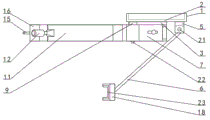
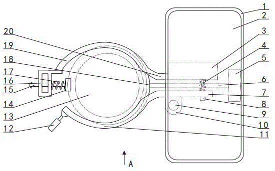
Fig. 1 is a schematic top view of the present invention;
FIG. 2 is a view in the direction A of FIG. 1;
FIG. 3 is a schematic view of the three-dimensional structure of the static semicircular channel steel of the present invention;
FIG. 4 is a schematic view of the three-dimensional structure of the movable semicircular channel steel of the present invention;
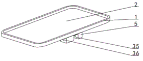
FIG. 5 is a schematic view of a three-dimensional structure of a bedplate according to the present invention;
fig. 6 is a schematic view of the bottom structure of the bedplate of the present invention;
FIG. 7 is a schematic view of the spatial structure of the slanting pole of the present invention;
fig. 8 is a schematic structural view of the utility model clamped on the insulator;
fig. 9 is a schematic diagram of the distribution and structure of the main equipment of an existing substation;
in the figure: 1. a step of table edge; 2. a platen; 3. a T-shaped plate; 4. a spring A; 5. connecting blocks; 6. a diagonal bar; 7. a straight channel steel A; 8. an expanding head; 9. a diameter expanding rod at the upper part of the shaft; 10. a shaft seat; 11. moving the semicircular channel steel; 12. a handle; 13. an insulator; 14. a channel steel locking block; 15. a top rod; 16. square tube steel; 17. a spring B; 18. arc channel steel; 19. a static semicircular channel steel; 20. a straight channel steel B; 21. a shaft lever A; 22. a shaft lever B; 23. a rubber inner face A; 24. filling blocks; 25. perforating; 26. a rubber inner surface B; 27. a pin hole A; 28. a cotter A; 29. a through hole; 30. a connecting plate; 31. a cotter pin B; 32. a long round hole; 33. a bearing; 34. a pin hole B; 35. opening the gap; 36. the shaft hole A; 37. a pin hole C; 38. a lower face; 39. a herringbone slope; 40. connecting the plug blocks; 41. a shaft hole B; 42. an insulator edge; 43. an insulator slot; 44. a high voltage cable; 45. a cross arm; 46. hanging a string of insulators; 47. a lightning rod; 48. a hanger; 49. an insulator; 50. a sulfur hexafluoride circuit breaker; 51. a current transformer; 52. a machine room; 53. a V-shaped insulator string; 54. a cement pillar; 55. a column insulator string; 56. a cement strut; 57. a cross post; 58. a column; 59. erecting a rod; 60. a wall; 61. a high-pressure tower.
Detailed Description
The present invention will be further described with reference to the following examples; the following examples are not intended to limit the present invention, and only serve as a means for supporting the implementation of the present invention, and any equivalent structural replacements within the technical framework disclosed by the present invention are all the protection scope of the present invention;
the transformer substation overhauling operation platform combined with the attached drawings 1 to 8 comprises a bedplate 2, a static semicircular channel steel 19, square pipe steel 16, a channel steel locking block 14, a movable semicircular channel steel 11, an inclined rod 6 and arc-shaped channel steel 18, the periphery of the upper surface of the bedplate 2 is respectively provided with an upward convex platform edge 1, the upward convex platform edge 1 prevents the falling of tools and workpieces during high-altitude operation, a rubber surface with a groove is arranged in the groove of the static semicircular channel steel 19, the rubber surface prevents the insulator edge 42 from being scratched, a straight channel steel B20 at the rear part of the static semicircular channel steel 19 is fixed at one side of the middle part of the lower part surface of the bedplate 2, the front part of the static semicircular channel steel 19 is provided with square tube steel 16, the outer part of the ejector rod 15 is movably penetrated in two through holes 29 of the square tube steel 16, the inner end of the ejector rod 15 is fixedly connected with the groove back surface of the channel steel locking block 14, a spring B17 is arranged on the ejector rod 15 between the groove back surface of the channel steel locking block 14 and the square tube steel 16; in the embodiment shown in fig. 1 and 3, considering that the square tube steel 16 should have a certain space from the insulator edge 42 when in use, the application shows that the connecting plate 30 arranged inside one side of the square tube steel 16 is fixedly connected with the front part of the semi-circular channel steel 19, so that the space between the inner surface of the square tube steel 16 and the insulator edge 42 can be obtained, and the front end part of the semi-circular channel steel 19 can be extended and then connected with the square tube steel 16 as an alternative; a pin hole A27 is formed in the ejector rod 15 outside the square tube steel 16, and a cotter pin A28 is arranged on the pin hole A27; the inner surface of the groove of the channel steel locking block 14 at the inner end of the ejector rod 15 is provided with a rubber inner surface B26; a handle 12 is arranged on the outer side of the front part of the movable semicircular channel steel 11, a rubber surface with a groove is arranged in the groove of the movable semicircular channel steel 11, a straight channel steel A7 at the rear part of the movable semicircular channel steel 11 is hinged to the other side of the middle part of the lower part surface of the bedplate 2 close to the front part, and a spring A4 is arranged between a straight channel steel B20 and the rear part of a straight channel steel A7; the upper insulator edge 42 is locked by a groove of the static semicircular channel steel 19, a groove of the channel steel locking block 14 and a groove of the movable semicircular channel steel 11; the upper end of the diagonal rod 6 is hinged with the outer part of the lower part surface of the bedplate 2, the arc-shaped channel steel 18 arranged at the lower end of the diagonal rod 6 is positioned at the rear lower part of the static semicircular channel steel 19 and the movable semicircular channel steel 11, a rubber inner surface A23 with a groove is arranged in the groove of the arc-shaped channel steel 18, the scratch to the insulator edge 42 is prevented by the rubber inner surface A23, and the arc-shaped channel steel 18 is propped against the lower insulator edge 42 to obtain the stable support of the bedplate 2.
With reference to fig. 1, 2, 3, 4 and 6, one side of the middle part of the lower surface of the bedplate 2 is fixedly connected with the upper end surface of the T-shaped plate 3, and a straight channel steel B20 at the rear part of the static semicircular channel steel 19 is fixed on a vertical plate at the lower part of the T-shaped plate 3; the other side of the middle part of the lower part surface of the bedplate 2 is fixedly connected with the upper end surface of the shaft upper diameter enlarging rod 9, a straight channel steel A7 at the rear part of a movable semicircular channel steel 11 is close to a shaft seat 10 arranged at the front part and is sleeved on an outer ring of a bearing 33, an inner ring of the bearing 33 is sleeved on the upper part of a shaft lever B22 at the lower part of the shaft upper diameter enlarging rod 9, a pin hole C37 is arranged at the lower end of a shaft lever B22, and the middle part of a split pin.
With reference to fig. 1, 2, 3, 4, 6 and 7, the upper end of the diagonal rod 6 is fixedly connected with the lower surface 38 of the connecting insert 40, the outer part of the lower surface of the bedplate 2 is provided with a connecting block 5, the middle part of the connecting block 5 is provided with a notch 35, the connecting block 5 is positioned in the notch 35, the middle part of the shaft lever a21 is positioned in the shaft hole B41 of the connecting block 5, and the two ends of the shaft lever a21 are respectively fixed in the shaft holes a36 of the walls of the two notches 35 of the connecting block 5 to form hinged connection; wherein the upper end surface of the connecting plug block 40 is a herringbone inclined surface 39, and the middle part of the upper end surface of the connecting plug block 40 is close to the upper plane in the opening 35 in the middle part of the opening bottom plane of the opening 35.
With reference to fig. 1, 2 and 3, a filling block 24 is arranged in a groove at the rear part of the straight channel steel B20, and a through hole 25 penetrating through the straight channel steel B20 is arranged at the rear part of the filling block 24; the rear part of the straight channel steel A7 is provided with a slotted hole 32, a spring A4 between the through hole 25 of the filling block 24 and the slotted hole A7 is sleeved on the pin penetrating rod, an expanding head 8 at one end of the pin penetrating rod is positioned on the outer side of the slotted hole A7 of the straight channel steel A7, the other end of the pin penetrating rod, which is close to the straight channel steel B, is positioned on the outer side of the through hole 25 of the straight channel steel B, and the cotter pin B31 penetrates into a pin hole B34 at the other end of the pin penetrating rod.
The transformer substation maintenance operation platform is implemented by combining the attached drawings 1 to 9, wherein the bedplate 2, the static semicircular channel steel 19, the movable semicircular channel steel 11, the channel steel locking block 14 and the arc-shaped channel steel 18 are formed by cold pressing by using steel plates with the thickness of between one millimeter and two millimeters; then, rubber sheets with proper sizes are used for being completely adhered in the grooves of the static semicircular channel steel 19 and the movable semicircular channel steel 11; similarly, the rubber inner surface B26 of the channel steel locking block 14 and the rubber inner surface A23 of the arc channel steel 18 are bonded by adopting the mode; the connection of the straight channel steel A7 and the shaft seat 10, the connection of the movable semicircular channel steel 11 and the handle 12, the connection of the connecting plate 30 and the static semicircular channel steel 19, the connection of the straight channel steel B20 and the filling block 24, the T-shaped plate 3 and the bedplate 2, the connection of the bedplate 2 and the connecting block 5 and the shaft upper diameter expanding rod 9, the connection of the inclined rod 6 and the connecting inserting block 40 and the arc-shaped groove steel 18, and the connection of the channel steel locking block 14 and the ejector rod 15 are all connected in a welding mode;
the assembling process comprises the following steps:
fixing the outer ring of the bearing 33 in a hole of the shaft seat 10, inserting a pin penetrating rod into a long round hole 32 of a straight channel steel A7 and a spring A4 by holding an expanding head 8, then inserting an inner hole of the inner ring of the bearing 33 into a shaft rod B22 at the lower part of an expanding rod 9 at the upper part of a shaft, wherein the tension of the spring A4 can be the inner side of square tube steel 16, and separating two thin rods of a cotter pin after the cotter pin penetrates into a pin hole C37; the pin penetrating rod penetrates through the through hole 25 of the filling block 24 and a corresponding hole of the straight channel steel B20 and then penetrates through a pin hole B34 of the pin penetrating rod through a cotter pin B31; sleeving a spring B17 on the ejector rod 15, then penetrating the outer end of the ejector rod 15 through the two through holes 29 of the square tube steel 16, and penetrating through a pin hole A27 in the outer end of the ejector rod 15 by using a cotter A28 to separate two thin rods of a cotter A28; the connecting plug block 40 at the upper end of the diagonal rod 6 is put into the notch 35 of the connecting block 5 and fixed by the shaft rod A21.
When in use, with reference to fig. 8 or 9, according to the condition that the object to be inspected is an insulator string 46 or a lightning rod 47 of an access frame, an insulator 49 fastener of a hanging frame 48 on the upper part of a vertical column 58, a sulfur hexafluoride breaker 50 on the upper end of a vertical column insulator string 55 on a cross column 57 on the upper end of a cement support rod 56, and a current transformer 51 on a V-shaped insulator string 53 on the upper end of a cement support rod 54, climbing objects are used for climbing up to an operation site, a rope is used for hoisting the application, then a hand pulls open a handle 12, so that a groove of a static semicircular steel channel 19 and a groove of a steel channel locking block 14 correspond to and are clamped with an insulator edge 42 of an insulator 13 at a proper position, after the handle 12 is released, the groove of a semicircular steel channel 11 is clamped with the other side of the insulator edge 42, then an arc-shaped steel channel 18 is clamped on the insulator edge 42 of a lower insulator, put into platen 2 after hoisting up with the saddlebag with the instrument work piece and can use the construction, use handle 12 to pull open after the construction is accomplished and move semicircle channel-section steel 11 alright take off this application rapidly.
The part of the utility model not detailed is prior art.