CN210243353U - A pliers torsion test device - Google Patents
A pliers torsion test device Download PDFInfo
- Publication number
- CN210243353U CN210243353U CN201921064456.9U CN201921064456U CN210243353U CN 210243353 U CN210243353 U CN 210243353U CN 201921064456 U CN201921064456 U CN 201921064456U CN 210243353 U CN210243353 U CN 210243353U
- Authority
- CN
- China
- Prior art keywords
- pliers
- torsion
- working platform
- seat
- hole
- Prior art date
- Legal status (The legal status is an assumption and is not a legal conclusion. Google has not performed a legal analysis and makes no representation as to the accuracy of the status listed.)
- Expired - Fee Related
Links
Images


Landscapes
- Investigating Strength Of Materials By Application Of Mechanical Stress (AREA)
Abstract
The utility model discloses a pliers torsion test device, belonging to the technical field of product quality detection and metering calibration test, comprising a cabinet, wherein the top of the cabinet is a working platform, and a bending resistance test piece clamping component, a pliers handle supporting component, a pliers pressure mechanism and a pliers torsion mechanism are assembled on the working platform; the bending-resistant test piece clamping assembly and the pliers handle supporting assembly of the pliers fixing mechanism are quickly and conveniently assembled and disassembled with the working platform, the distance between the bending-resistant test piece clamping assembly and the pliers handle supporting assembly is flexibly adjusted, so that the bending-resistant test piece clamping assembly and the pliers handle supporting assembly can be suitable for tests of pliers of different types and specifications, and the bending-resistant test piece clamping assembly and the pliers handle supporting assembly can be mutually combined for; through mutually supporting the use between pliers fixed establishment, pliers pressure mechanism and the pliers torsion mechanism, realized a pliers torsion test device.
Description
Technical Field
The utility model belongs to the technical field of product quality detects, measurement calibration test, in particular to pliers torsion test device.
Background
For the test tests of the clamp-twist pliers, the shearing pliers and the clamp-twist shearing pliers, the state establishes a standard GB/T6291-2013 test method for the clamp-twist pliers and the shearing pliers, in the method, except for the test methods of the surfaces, the gaps of the cutting edges, the gaps of the mouth tops, the hardness of the clamping surfaces, the hardness of the cutting edges and the like of the pliers, the test methods of the bending strength test, the shearing performance test and the torsion test of the pliers are mainly specified, however, the specific test devices are not uniformly specified in the standard.
The patent literature on forceps testing is mainly: the Chinese patent application No. CN201810025659.0 discloses a hydraulic clamp fatigue test stand, Chinese patent application No. CN201510371340.X, discloses a main body frame for a clamp test stand, Chinese patent application No. CN201821697434.1, discloses a clamp multifunctional detection simple test stand and the like, and the technical schemes disclosed above are not designed according to the requirements of national standard GB/T6291 and 2013 & lt & gt test method & gt of clamp and twist clamp, so that special test detection equipment for performing torsion test on the clamp is absent, the quality detection and calibration test efficiency of the clamp is low, and the working efficiency is affected.
SUMMERY OF THE UTILITY MODEL
The utility model aims to provide a pliers torsion test device; the technical scheme adopted for achieving the purpose is as follows:
a clamp torsion testing device comprises a cabinet, wherein the top of the cabinet is provided with a working platform, and a bending-resistant test piece clamping assembly, a clamp handle supporting assembly, a clamp pressure mechanism and a clamp torsion mechanism are assembled on the working platform;
the bending-resistant test piece clamping assembly comprises a clamping support arm fixedly connected to the working platform, and a clamping seat for clamping a bending-resistant test piece is fixed at the upper end of the clamping support arm; the pliers handle supporting assembly comprises a supporting seat fixedly connected to the working platform, and a lifting supporting table is arranged at the top of the supporting seat;
the forceps pressure mechanism comprises a supporting bent arm fixedly connected to the working platform, a servo electric cylinder with a piston rod vertically arranged downwards is fixed at the top end of the supporting bent arm, a forceps pressure head is fixed at the tail end of the piston rod, and a pressure sensor is arranged between the forceps pressure head and the tail end of the piston rod;
the pliers torsion mechanism comprises a guide rail seat fixedly connected to the working platform, a guide rail arranged in the left-right direction is fixed on the guide rail seat, a sliding plate is connected onto the guide rail in a sliding manner, a worm gear mechanism is fixed on the sliding plate, an output shaft of the worm gear mechanism points to the direction of the pliers handle supporting assembly, a torsion sensor is mounted at the tail end of the output shaft of the worm gear mechanism, and a pliers torsion head is mounted at the tail end of the output shaft of the torsion sensor; the bottom of the sliding plate is provided with a threaded hole arranged along the left-right direction, the guide rail seat is rotatably connected with a power screw rod penetrating through the threaded hole, and the right end of the power screw rod is provided with a manual rotating wheel.
Further, the array is equipped with a plurality of installation screw holes on work platform, both sides all are equipped with the engaging lug around centre gripping support arm bottom and supporting seat bottom both sides around, are equipped with the rectangular shape through-hole of level on the engaging lug, are equipped with fixing bolt in the rectangular shape through-hole of level, fixing bolt and installation screw hole threaded connection, fixing bolt's bolt cap is greater than the width of the rectangular shape through-hole of level, and the rectangular shape through-hole of level sets up along left right direction.
Further, be equipped with vertical rectangular shape through-hole on the grip slipper, be equipped with fixing bolt in vertical rectangular shape through-hole, fixing bolt and centre gripping support arm upper end threaded connection, fixing bolt's bolt cap is greater than the width of vertical rectangular shape through-hole, and vertical rectangular shape through-hole sets up along vertical direction.
Furthermore, the pliers pressure head includes the pressure head seat of fixed connection at the piston rod end, is equipped with two supplementary arms that keep off on the pressure head seat side by side, and when the pliers pressure head downstream pressed the pliers handle, the pliers handle was located between two supplementary arms that keep off.
Furthermore, the pliers wrench head comprises a wrench head seat fixed at the tail end of the output shaft of the torque sensor, two blocking claws are arranged on the wrench head seat side by side, and when the pliers wrench head moves to the pliers handle, the pliers handle is located between the two blocking claws.
The utility model discloses the beneficial effect who has does: (1) the bending-resistant test piece clamping assembly and the pliers handle supporting assembly of the pliers fixing mechanism are quickly and conveniently assembled and disassembled with the working platform, the distance between the bending-resistant test piece clamping assembly and the pliers handle supporting assembly is flexibly adjusted, so that the bending-resistant test piece clamping assembly and the pliers handle supporting assembly can be suitable for tests of pliers of different types and specifications, and the bending-resistant test piece clamping assembly and the pliers handle supporting assembly can be mutually combined for;
(2) the arrangement of the horizontal strip-shaped through holes at the bottoms of the bending-resistant test piece clamping assembly and the pliers handle supporting assembly realizes the adjustment of the left and right positions of the horizontal strip-shaped through holes, so that the detection is more accurate;
(3) the upper and lower positions of the clamping seat and the supporting platform are flexibly adjusted, so that the fixation of the pliers with different models and specifications can be met;
(4) the servo electric cylinder and the pressure sensor of the pliers pressure mechanism are arranged, so that the pressure value and the displacement value, namely the stress value and the deformation quantity of the pliers, can be accurately measured;
(5) the power screw rod is manually rotated in the pliers torsion mechanism, so that the pliers torsion head is conveniently driven to move left and right, and the handles of the pliers are quickly and accurately clamped;
(6) the arrangement of the worm gear mechanism in the pliers torsion mechanism has large output torsion, so that the pliers torsion stress is ensured to meet the standard requirement; meanwhile, the torque sensor is arranged to realize the accurate measurement of the torque value of the handle of the pliers;
(7) through mutually supporting the use between pliers fixed establishment, pliers pressure mechanism and the pliers torsion mechanism, realized a pliers torsion test device.
Drawings
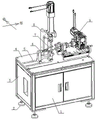
Fig. 1 is a schematic perspective view of the present invention;
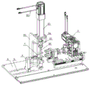
FIG. 2 is a perspective view of the upper portion of the cabinet of FIG. 1;
FIG. 3 is a perspective view of the forceps holding mechanism;
fig. 4 is a perspective view of the torque mechanism of the pliers.
Detailed Description
The present invention will be further described with reference to the accompanying drawings.
As shown in fig. 1 and 2, the present invention includes a cabinet 3, a working platform 4 is arranged on the top of the cabinet 3, and a pliers fixing mechanism 6, a pliers pressure mechanism 8 and a pliers torsion mechanism 9 are assembled on the working platform 4;
as shown in fig. 3, the forceps fixing mechanism 6 comprises a bending-resistant test strip clamping component and a forceps handle supporting component in sequence from left to right, the bending-resistant test strip clamping component comprises a clamping supporting arm 614 fixedly connected to the working platform 4, and a clamping seat 62 for clamping a bending-resistant test strip is fixed at the upper end of the clamping supporting arm 614; the pliers handle supporting assembly comprises a supporting seat 68 fixedly connected to the working platform 4, and a lifting supporting table 66 is arranged at the top of the supporting seat 68;
as shown in fig. 1 and fig. 2, the forceps pressure mechanism 8 includes a support curved arm 81 fixedly connected to the working platform 4, a servo electric cylinder 83 with a piston rod vertically arranged downwards is fixed at the top end of the support curved arm 81, a forceps pressure head 86 is fixed at the end of the piston rod through a coupling 84, and a pressure sensor 85 is arranged between the forceps pressure head 86 and the end of the piston rod;
as shown in fig. 4, the forceps torsion mechanism 9 includes a guide rail seat 98 fixedly connected to the working platform 4, a guide rail 910 arranged along the left-right direction is fixed on the guide rail seat 98, a sliding plate 99 is slidably connected to the guide rail 910, a worm gear mechanism 96 is fixed on the sliding plate 99, an output shaft 93 of the worm gear mechanism 96 points to the direction of the forceps handle support assembly, a torsion sensor 912 is installed at the tail end of the output shaft 93 of the worm gear mechanism 96, i.e. the torsion sensor 912 is coaxially connected with an input shaft of the torsion sensor 912, and a forceps torsion head 91 is installed on an output shaft of the torsion sensor 912; a threaded hole is formed in the bottom of the sliding plate 99 in the left-right direction, a power screw 911 is rotatably connected to the rail base 98 and penetrates through the threaded hole, and a manual rotation wheel 97 is provided at the right end of the power screw 911.
As shown in fig. 1 and 2, a plurality of mounting screw holes 5 are arranged on the working platform 4 in an array manner, engaging lugs are arranged on the front side and the rear side of the bottom of the clamping support arm 614 and the front side and the rear side of the bottom of the support seat 68, horizontal long-strip-shaped through holes 613, 611, 69 are correspondingly arranged on the engaging lugs, fixing bolts are assembled in the horizontal long-strip-shaped through holes 613, 69, the fixing bolts are in threaded connection with the mounting screw holes 5, bolt caps of the fixing bolts are larger than the horizontal long-strip-shaped through holes 613, 69, the horizontal long-strip-shaped through holes 613, 69 are arranged in the left-right direction, and fine adjustment in the left-right direction can be carried out on the bending-resistant.
Be equipped with vertical rectangular shape through-hole on holder 62, be equipped with fixing bolt 61 in vertical rectangular shape through-hole, fixing bolt 61 and centre gripping support arm 614 upper end threaded connection, fixing bolt 61's bolt cap is greater than the width of vertical rectangular shape through-hole, and vertical rectangular shape through-hole sets up along vertical direction to can carry out the fine setting of direction from top to bottom to holder 62.
In order to ensure that the pliers pressure head 86 does not have dislocation and stable force application when applying pressure to the pliers handle, the tail end of the pliers pressure head 86 is provided with an arc-shaped inner groove, and the pliers handle is positioned in the arc-shaped inner groove; or other structures are adopted instead, for example, the pliers pressure head comprises a pressure head seat fixedly connected to the tail end of the piston rod, two auxiliary blocking arms are arranged on the pressure head seat side by side, and when the pliers pressure head moves downwards to press the pliers handle, the pliers handle is positioned between the two auxiliary blocking arms.
The wrench head 91 of the pliers comprises a torque head seat 913 fixed at the end of the output shaft of the torque sensor 912, and two claws 914 are arranged on the torque head seat 913 side by side, and when the wrench head 91 of the pliers moves towards the handle of the pliers, the handle 914 of the pliers is located between the two claws.
A bearing block 92 is fixed to the slide plate 99, and a bearing for supporting the output shaft 93 of the torque sensor 96 is fixed to the bearing block 92.
As shown in fig. 1, a storage chamber is provided in the cabinet 3, a storage chamber door 1 is provided on the cabinet 3, and adjusting legs 2 are provided at the bottom of four corners of the cabinet 3.
The utility model discloses when carrying out torsion test:
fixing the bending-resistant test piece clamping component and the pliers handle supporting component of the pliers fixing mechanism 6 on the working platform 4, inserting a torsion test piece into the clamping seat 62, wherein the selection of the torsion test piece meets the requirement of test specification, then adjusting the left and right positions of the bending-resistant test piece clamping component and the pliers handle supporting component according to the type, the size and the specification of a pliers to be tested, adjusting the height of the clamping seat 62 and the supporting platform 66 to ensure that the jaw of the pliers 7 clamps the torsion test piece, and the lower handle of the pliers 7 is supported on the supporting platform 66, wherein the lifting adjustment of the supporting platform 66 can be realized by adopting various existing technologies, exerting pressure after the pliers are fixed, rotating the manual rotating wheel 97 to drive the power screw 911 to rotate so as to drive the sliding plate 99 and the parts to move leftwards, the pliers twisting head 91 clamps two handles, and then inputting a control signal to the servo electric cylinder 83 through a control data line 82, the servo electric cylinder 83 actuates the piston rod to drive the forceps pressure head 86 to press the forceps handle, and 50% of the bending strength load specified in the corresponding product standard is applied to the forceps handle;
finally, a control signal is input to the servo motor 95 through the control data line 94, the servo motor 95 drives the worm gear mechanism 96 to work, the output shaft 93 applies a torsion value specified in the corresponding product standard to the forceps handle in the clockwise direction and the anticlockwise direction, and whether the torsion angle meets the specified value in the corresponding product standard is judged.
Finally, it should be noted that: the above embodiments are only used to illustrate the technical solution of the present invention, and not to limit it; although the present invention has been described in detail with reference to the foregoing embodiments, it should be understood by those skilled in the art that: it is to be understood that modifications may be made to the above-described arrangements in the embodiments or equivalents may be substituted for some of the features of the embodiments, but such modifications or substitutions do not depart from the spirit and scope of the present invention.
Claims (5)
Priority Applications (1)
| Application Number | Priority Date | Filing Date | Title |
|---|---|---|---|
| CN201921064456.9U CN210243353U (en) | 2019-07-09 | 2019-07-09 | A pliers torsion test device |
Applications Claiming Priority (1)
| Application Number | Priority Date | Filing Date | Title |
|---|---|---|---|
| CN201921064456.9U CN210243353U (en) | 2019-07-09 | 2019-07-09 | A pliers torsion test device |
Publications (1)
| Publication Number | Publication Date |
|---|---|
| CN210243353U true CN210243353U (en) | 2020-04-03 |
Family
ID=69990309
Family Applications (1)
| Application Number | Title | Priority Date | Filing Date |
|---|---|---|---|
| CN201921064456.9U Expired - Fee Related CN210243353U (en) | 2019-07-09 | 2019-07-09 | A pliers torsion test device |
Country Status (1)
| Country | Link |
|---|---|
| CN (1) | CN210243353U (en) |
Cited By (1)
| Publication number | Priority date | Publication date | Assignee | Title |
|---|---|---|---|---|
| CN114643545A (en) * | 2020-12-18 | 2022-06-21 | 北京福田康明斯发动机有限公司 | Screw up rifle calibration auxiliary device |
-
2019
- 2019-07-09 CN CN201921064456.9U patent/CN210243353U/en not_active Expired - Fee Related
Cited By (2)
| Publication number | Priority date | Publication date | Assignee | Title |
|---|---|---|---|---|
| CN114643545A (en) * | 2020-12-18 | 2022-06-21 | 北京福田康明斯发动机有限公司 | Screw up rifle calibration auxiliary device |
| CN114643545B (en) * | 2020-12-18 | 2024-04-05 | 北京福田康明斯发动机有限公司 | Tightening gun calibration auxiliary device |
Similar Documents
| Publication | Publication Date | Title |
|---|---|---|
| CN110231229B (en) | A comprehensive test device for twisting pliers and cutting pliers | |
| CN215115650U (en) | Screwdriver head torque force tester | |
| CN216771323U (en) | Reliability detection device | |
| CN109900556B (en) | A self-coordinated lateral fretting loading device for fretting fatigue test | |
| CN214538352U (en) | An electric torque wrench, pneumatic torque wrench calibration device | |
| CN204913656U (en) | Screw rod drilling tool test bench is from big moment of torsion clamping device of centering | |
| CN215767985U (en) | Rock strength index detects with mechanism of exerting pressure | |
| CN210221672U (en) | A test device for flexural strength and shear performance of pliers | |
| CN211206018U (en) | Sample positioning and adjusting device of tensile testing machine | |
| CN218412013U (en) | Robot part strength tester | |
| CN216830430U (en) | Engineering plastic plate processing and positioning device | |
| CN218885228U (en) | Automobile door plate handrail force measuring tool | |
| CN215525395U (en) | A hardness testing mechanism for improving the applicability of metal workpieces | |
| CN210741290U (en) | Utensil is examined to clamp force adjustable automobile ornaments | |
| CN224176067U (en) | A spring impactor calibration test device | |
| CN209014369U (en) | Elastomer fatigue testing machine | |
| CN116499868B (en) | A clamping machine for testing the mechanical properties of metallic materials | |
| CN210426983U (en) | Hardware checking fixture | |
| CN220367088U (en) | Nodular cast iron performance test detection device | |
| CN220305053U (en) | Static shearing resistance detection device for assembled perforated steel plate connecting piece | |
| CN218916797U (en) | Display base hinge aging test equipment | |
| CN207106940U (en) | A kind of clamping device | |
| CN215985001U (en) | Torque wrench detection mechanism | |
| CN223819963U (en) | Welding fixing device for electromechanical mounting bracket | |
| CN223650305U (en) | A fastening detection device for steel structure engineering |
Legal Events
| Date | Code | Title | Description |
|---|---|---|---|
| GR01 | Patent grant | ||
| GR01 | Patent grant | ||
| CF01 | Termination of patent right due to non-payment of annual fee |
Granted publication date: 20200403 Termination date: 20210709 |
|
| CF01 | Termination of patent right due to non-payment of annual fee |