CN210237714U - Thrust wheel heat treatment device - Google Patents
Thrust wheel heat treatment device Download PDFInfo
- Publication number
- CN210237714U CN210237714U CN201921046264.5U CN201921046264U CN210237714U CN 210237714 U CN210237714 U CN 210237714U CN 201921046264 U CN201921046264 U CN 201921046264U CN 210237714 U CN210237714 U CN 210237714U
- Authority
- CN
- China
- Prior art keywords
- heat treatment
- water outlet
- push rod
- timer
- electric push
- Prior art date
- Legal status (The legal status is an assumption and is not a legal conclusion. Google has not performed a legal analysis and makes no representation as to the accuracy of the status listed.)
- Active
Links
- 238000010438 heat treatment Methods 0.000 title claims abstract description 25
- XLYOFNOQVPJJNP-UHFFFAOYSA-N water Substances O XLYOFNOQVPJJNP-UHFFFAOYSA-N 0.000 claims abstract description 37
- 230000006698 induction Effects 0.000 claims description 19
- 238000009413 insulation Methods 0.000 claims description 4
- 229910052593 corundum Inorganic materials 0.000 claims description 3
- 239000010431 corundum Substances 0.000 claims description 3
- 238000000034 method Methods 0.000 description 5
- 238000001816 cooling Methods 0.000 description 3
- 230000000694 effects Effects 0.000 description 2
- 101001081183 Homo sapiens Minor histocompatibility protein HB-1 Proteins 0.000 description 1
- 102100027749 Minor histocompatibility protein HB-1 Human genes 0.000 description 1
- 230000009286 beneficial effect Effects 0.000 description 1
Images

Classifications
-
- Y—GENERAL TAGGING OF NEW TECHNOLOGICAL DEVELOPMENTS; GENERAL TAGGING OF CROSS-SECTIONAL TECHNOLOGIES SPANNING OVER SEVERAL SECTIONS OF THE IPC; TECHNICAL SUBJECTS COVERED BY FORMER USPC CROSS-REFERENCE ART COLLECTIONS [XRACs] AND DIGESTS
- Y02—TECHNOLOGIES OR APPLICATIONS FOR MITIGATION OR ADAPTATION AGAINST CLIMATE CHANGE
- Y02P—CLIMATE CHANGE MITIGATION TECHNOLOGIES IN THE PRODUCTION OR PROCESSING OF GOODS
- Y02P10/00—Technologies related to metal processing
- Y02P10/25—Process efficiency
Landscapes
- General Induction Heating (AREA)
Abstract
The utility model discloses a supporting wheel heat treatment device, which comprises a bottom bin and a top plate, wherein two grooves are fixedly arranged inside the bottom bin, the top ends of the two grooves are fixedly connected with a limiting plate, the top part of one side of the bottom bin is fixedly provided with a water inlet, the top part of the other side of the bottom bin is fixedly provided with a water outlet, the bottom part of the other side of the bottom bin is fixedly provided with a water outlet, and both sides of the top end of the bottom bin are respectively and fixedly connected with both sides of the bottom end of the top plate through vertical plates, no manual timing is required.
Description
Technical Field
The utility model relates to a heat treatment device, in particular to thrust wheel heat treatment device belongs to thrust wheel processing technology field.
Background
The thrust wheel is one of four wheels and one belt of a chassis of the crawler-type engineering machine, and mainly has the functions of supporting the weight of an excavator and a bulldozer and enabling the crawler to move forward along the wheel, and in the working process, the thrust wheel bears huge friction force.
SUMMERY OF THE UTILITY MODEL
An object of the utility model is to provide a thrust wheel heat treatment device to solve the common thrust wheel heat treatment device who provides in the above-mentioned background art and be not convenient for carry out the problem of heat treatment to two thrust wheels simultaneously.
In order to achieve the above object, the utility model provides a following technical scheme: the utility model provides a thrust wheel heat treatment device, includes end storehouse and roof, two recesses, two are seted up to the inside fixed of end storehouse the equal fixedly connected with limiting plate in top of recess, the top of end storehouse one side is fixed and has been seted up the inlet opening, the top of end storehouse opposite side is fixed and has been seted up the apopore, the bottom of end storehouse opposite side is fixed and has been seted up the wash port, the both sides on end storehouse top all through the riser respectively with the both sides fixed connection of roof bottom, one side fixed mounting of one of them riser has the timer, the middle part of roof bottom has electric putter through mounting panel fixed mounting, electric putter's telescopic link and the middle part fixed connection on connecting plate top, the bottom fixed mounting of connecting plate has the induction coil of two series connections.
As a preferred technical scheme of the utility model, the outlet end fixed connection of inlet opening and inlet tube, the apopore holds fixed connection with the intaking of outlet pipe, the wash port holds fixed connection with the intaking of drain pipe, the fixed valve that is equipped with in middle part of drain pipe.
As an optimized technical proposal of the utility model, the bottom fixing of the connecting plate is provided with a corundum heat insulation plate.
As an optimal technical scheme of the utility model, two the induction coil is coaxial with two recesses respectively.
As a preferred technical scheme of the utility model, the equal fixed mounting in four corners of end storehouse bottom has the supporting leg, four the equal fixed covering in bottom of supporting leg has the rubber pad.
As an optimal technical scheme of the utility model, induction coil and timer electric connection, the fixed flush mounting plate that is equipped with in one side of one of them riser, flush mounting plate's surface is equipped with electric putter switch and timer switch, electric putter and timer are respectively through electric putter switch and timer switch and power electric connection.
Compared with the prior art, the beneficial effects of the utility model are that: the utility model relates to a supporting wheel heat treatment device, two grooves are fixedly arranged in the bottom bin, two supporting wheels can be respectively placed in the two grooves, a limiting plate can limit the supporting wheels, a telescopic rod of an electric push rod is extended through an electric push rod switch, two induction coils can respectively cover the two supporting wheels, the two supporting wheels are simultaneously subjected to heat treatment, the heat treatment speed of the supporting wheels is improved, the heating time of the induction coils on the supporting wheels can be set through a timer, manual timing is not needed, the accuracy of the heating time of the induction coils on the supporting wheels is ensured, after the heat treatment is finished, the telescopic rod of the electric push rod is contracted through the electric push rod switch, cold water is injected into a water inlet through a water inlet pipe, the supporting wheels can be rapidly cooled after the cold water reaches the bottom bin through the water inlet hole, the cooling effect on the supporting wheels is improved, the cold water can be discharged through a water outlet hole in the flowing process, after cooling, water supply to the bottom bin is stopped, the valve is opened, and water in the bottom bin can be discharged through the water discharge hole.
Drawings
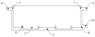
Fig. 1 is a schematic structural view of the present invention;
fig. 2 is a schematic structural view of the bottom bin of the present invention.
In the figure: 1. a bottom bin; 2. supporting legs; 3. a groove; 4. a limiting plate; 5. a water inlet hole; 6. a water inlet pipe; 7. a water outlet hole; 8. a water outlet pipe; 9. a drain hole; 10. a drain pipe; 11. a valve; 12. a vertical plate; 13. a top plate; 14. mounting a plate; 15. an electric push rod; 16. a connecting plate; 17. an induction coil; 18. a timer; 19. a switch panel.
Detailed Description
The technical solutions in the embodiments of the present invention will be described clearly and completely with reference to the accompanying drawings in the embodiments of the present invention, and it is obvious that the described embodiments are only some embodiments of the present invention, not all embodiments. Based on the embodiments in the present invention, all other embodiments obtained by a person skilled in the art without creative work belong to the protection scope of the present invention.
Please refer to fig. 1-2, the utility model provides a thrust wheel heat treatment device, including end storehouse 1 and roof 13, two recesses 3 have been seted up to the inside fixed of end storehouse 1, the equal fixedly connected with limiting plate 4 in top of two recesses 3, the fixed inlet opening 5 that has seted up in top of end storehouse 1 one side, the fixed apopore 7 that has seted up in top of end storehouse 1 opposite side, the fixed wash port 9 that has seted up in bottom of end storehouse 1 opposite side, the both sides on end storehouse 1 top all through riser 12 respectively with the both sides fixed connection of roof 13 bottom, one side fixed mounting of one of them riser 12 has timer 18, the middle part of roof 13 bottom has electric putter 15 through mounting panel 14 fixed mounting, the middle part fixed connection on electric putter's 15 telescopic link and the 16 tops of connecting plate, the bottom fixed mounting of connecting plate 16 has two induction coils 17 of establishing ties.
Preferably, the inlet opening 5 is fixedly connected with the outlet end of the inlet pipe 6, the outlet opening 7 is fixedly connected with the inlet end of the outlet pipe 8, the outlet pipe 8 is conveniently and respectively connected with the water feeding pool and the water outlet pool through the inlet pipe 6, the drain hole 9 is fixedly connected with the inlet end of the drain pipe 10, the valve 11 is fixedly arranged in the middle of the drain pipe 10, and the drainage speed of the drain pipe 10 can be adjusted through the valve 11.
Preferably, the corundum heat insulation plate is fixedly arranged at the bottom end of the connecting plate 16, so that the heat insulation effect is good.
Preferably, two induction coils 17 are respectively coaxial with the two grooves 3, and the two induction coils 17 can respectively cover the two thrust wheels.
Preferably, four equal fixed mounting in corner of 1 bottom in the end storehouse have supporting leg 2, and the equal fixed covering in bottom of four supporting leg 2 has the rubber pad, has guaranteed the stability in end storehouse 1.
Preferably, the induction coil 17 is electrically connected with a timer 18, a switch panel 19 is fixedly arranged on one side of one of the vertical plates 12, an electric push rod switch and a timer switch are arranged on the surface of the switch panel 19, the electric push rod 15 and the timer 18 are respectively electrically connected with a power supply through the electric push rod switch and the timer switch, and the electric push rod 15 and the timer 18 are respectively conveniently turned on and off through the electric push rod switch and the timer switch.
When the heat treatment device is used, firstly, two thrust wheels to be processed are taken out and are respectively placed in the two grooves 3, then the telescopic rod of the electric push rod 15 with the model being XDHA12-200 is extended through the electric push rod switch, the telescopic rod of the electric push rod 15 drives the two induction coils 17 with the model being HB-1Y to descend in the extending process, the two induction coils 17 respectively cover the two thrust wheels, the timer switch is turned on, the timing time is set through the timer 18 with the model being AL-06, the timer 18 starts the induction coils 17 to heat the thrust wheels in the timing range, after the timing time is reached, the induction coils 17 stop heating the thrust wheels, after the heating is finished, the telescopic rod of the electric push rod 15 is contracted through the electric push rod switch, the telescopic rod of the electric push rod 15 drives the induction coils 17 to ascend in the contracting process, then connect water supply tank and play pond respectively with inlet tube 6 and outlet pipe 8, inject cold water in toward inlet opening 5 through inlet tube 6, cold water passes through inlet opening 5 and arrives end storehouse 1 back, can cool off the thrust wheel fast, and cold water is discharged to the play pond at the in-process apopore 7 that flows, and after the cooling, open valve 11, with end storehouse 1 in the water through drain pipe 10 discharge can.
In the description of the present invention, it should be understood that the indicated orientation or positional relationship is based on the orientation or positional relationship shown in the drawings, and is only for convenience of description and simplification of description, and does not indicate or imply that the indicated device or element must have a particular orientation, be constructed and operated in a particular orientation, and thus should not be construed as limiting the present invention.
Claims (6)
1. A thrust wheel heat treatment device comprises a bottom bin (1) and a top plate (13), and is characterized in that two grooves (3) are fixedly formed in the bottom bin (1), limiting plates (4) are fixedly connected to the top ends of the two grooves (3), a water inlet hole (5) is fixedly formed in the top of one side of the bottom bin (1), a water outlet hole (7) is fixedly formed in the top of the other side of the bottom bin (1), a water outlet hole (9) is fixedly formed in the bottom of the other side of the bottom bin (1), two sides of the top end of the bottom bin (1) are respectively and fixedly connected with two sides of the bottom end of the top plate (13) through vertical plates (12), a timer (18) is fixedly mounted on one side of one vertical plate (12), an electric push rod (15) is fixedly mounted in the middle of the bottom end of the top plate (13) through a mounting plate (14), and a telescopic rod of the electric push rod (15) is fixedly, and two induction coils (17) connected in series are fixedly mounted at the bottom end of the connecting plate (16).
2. The heat treatment apparatus for a bogie as recited in claim 1, wherein: the water inlet hole (5) is fixedly connected with the water outlet end of the water inlet pipe (6), the water outlet hole (7) is fixedly connected with the water inlet end of the water outlet pipe (8), the water outlet hole (9) is fixedly connected with the water inlet end of the water outlet pipe (10), and the middle of the water outlet pipe (10) is fixedly provided with a valve (11).
3. The heat treatment apparatus for a bogie as recited in claim 1, wherein: and a corundum heat insulation plate is fixedly arranged at the bottom end of the connecting plate (16).
4. The heat treatment apparatus for a bogie as recited in claim 1, wherein: the two induction coils (17) are respectively coaxial with the two grooves (3).
5. The heat treatment apparatus for a bogie as recited in claim 1, wherein: four equal fixed mounting in corner of end storehouse (1) bottom have supporting leg (2), four the equal fixed covering in bottom of supporting leg (2) has the rubber pad.
6. The heat treatment apparatus for a bogie as recited in claim 1, wherein: the induction coil (17) is electrically connected with the timer (18), a switch panel (19) is fixedly arranged on one side of one vertical plate (12), an electric push rod switch and a timer switch are arranged on the surface of the switch panel (19), and the electric push rod (15) and the timer (18) are respectively electrically connected with the power supply through the electric push rod switch and the timer switch.
Priority Applications (1)
| Application Number | Priority Date | Filing Date | Title |
|---|---|---|---|
| CN201921046264.5U CN210237714U (en) | 2019-07-06 | 2019-07-06 | Thrust wheel heat treatment device |
Applications Claiming Priority (1)
| Application Number | Priority Date | Filing Date | Title |
|---|---|---|---|
| CN201921046264.5U CN210237714U (en) | 2019-07-06 | 2019-07-06 | Thrust wheel heat treatment device |
Publications (1)
| Publication Number | Publication Date |
|---|---|
| CN210237714U true CN210237714U (en) | 2020-04-03 |
Family
ID=69989916
Family Applications (1)
| Application Number | Title | Priority Date | Filing Date |
|---|---|---|---|
| CN201921046264.5U Active CN210237714U (en) | 2019-07-06 | 2019-07-06 | Thrust wheel heat treatment device |
Country Status (1)
| Country | Link |
|---|---|
| CN (1) | CN210237714U (en) |
-
2019
- 2019-07-06 CN CN201921046264.5U patent/CN210237714U/en active Active
Similar Documents
| Publication | Publication Date | Title |
|---|---|---|
| CN211803925U (en) | Drilling equipment is used in tubular product processing convenient to it is fixed | |
| CN206887866U (en) | A kind of improved drainage arrangement | |
| CN212982998U (en) | A heating and quenching device for processing heterosexual induction coils | |
| CN205219995U (en) | High -efficient vacuum film covering machine in plane | |
| CN213261995U (en) | Storage battery charging protection device for new energy electric vehicle | |
| CN213680838U (en) | Hot dipping plastic device for surface of metal workpiece | |
| CN211867169U (en) | A cutting equipment for copper rod production | |
| CN111036609B (en) | Acid dip pickle is used in stone material processing | |
| CN211660283U (en) | Electrified spray set | |
| CN218576806U (en) | Adjustable polyurethane high-pressure casting machine | |
| CN211916570U (en) | Novel grinding wheel curing oven | |
| CN210456575U (en) | A kind of reclaiming turning placed structure platform | |
| CN203417824U (en) | Glue-melting equipment for low-pressure glue-injection machine | |
| CN211438519U (en) | Protective device for automatic welding machine | |
| CN208620845U (en) | A kind of cooling system of intermediate frequency furnace | |
| CN206478309U (en) | A kind of concrete pump line corner fixture | |
| CN219465043U (en) | Steel bar butt welding machine | |
| CN206124077U (en) | Ice machine foaming fixture | |
| CN207459143U (en) | One kind is convenient for coupler cavity trip bolt frock | |
| CN206661792U (en) | A kind of ore cleaning equipment of high-efficiency environment friendly | |
| CN215590759U (en) | Transfer device is used in production of water-bath formula electrical heating double entry heater | |
| CN206004190U (en) | A kind of box-type substation top cover transom | |
| CN216743151U (en) | But water supply and drainage pipeline of quick butt joint | |
| CN213858849U (en) | Clamping device for wood guardrail water-proof treatment | |
| CN216005940U (en) | Energy-saving steel processing heat treatment generation device |
Legal Events
| Date | Code | Title | Description |
|---|---|---|---|
| GR01 | Patent grant | ||
| GR01 | Patent grant |