CN210223894U - Novel temperature controller with overheat protection function - Google Patents
Novel temperature controller with overheat protection function Download PDFInfo
- Publication number
- CN210223894U CN210223894U CN201921318877.XU CN201921318877U CN210223894U CN 210223894 U CN210223894 U CN 210223894U CN 201921318877 U CN201921318877 U CN 201921318877U CN 210223894 U CN210223894 U CN 210223894U
- Authority
- CN
- China
- Prior art keywords
- slide
- fixed
- temperature controller
- plate
- overheat protection
- Prior art date
- Legal status (The legal status is an assumption and is not a legal conclusion. Google has not performed a legal analysis and makes no representation as to the accuracy of the status listed.)
- Active
Links
- 239000000919 ceramic Substances 0.000 claims abstract description 10
- 239000004020 conductor Substances 0.000 claims 4
- 230000000149 penetrating effect Effects 0.000 claims 2
- 230000000694 effects Effects 0.000 abstract description 10
- 238000009413 insulation Methods 0.000 abstract description 5
- 238000005381 potential energy Methods 0.000 abstract description 4
- 230000003068 static effect Effects 0.000 abstract description 4
- 230000001105 regulatory effect Effects 0.000 abstract description 3
- 230000002277 temperature effect Effects 0.000 abstract description 3
- 230000004048 modification Effects 0.000 description 2
- 238000012986 modification Methods 0.000 description 2
- 230000001012 protector Effects 0.000 description 2
- 230000009286 beneficial effect Effects 0.000 description 1
- 238000010438 heat treatment Methods 0.000 description 1
- 238000013021 overheating Methods 0.000 description 1
- 238000005057 refrigeration Methods 0.000 description 1
Images
Landscapes
- Thermally Actuated Switches (AREA)
Abstract
The utility model belongs to the technical field of the temperature controller, especially, be a novel temperature controller with overheat protection function, which comprises a housin, the bottom of casing is run through and is fixed with ceramic heat conduction piece, a lateral wall of casing is fixed with the current conducting plate, the one end bottom of current conducting plate is fixed with the static contact, another lateral wall of casing is fixed with the insulation board, the one end bottom of insulation board is fixed with the bimetallic strip. The utility model discloses a set up the fuse between bimetallic strip and conducting block, break down when the bimetallic strip, be heated when unable emergence deformation, when the high temperature of equipment was too high, the fuse can break off under the high temperature effect, thereby play open circuit's effect, so can play overheat protection's effect, through setting up T type pole, first slide, the second slide, the threaded rod, change the handle, the connecting plate, connecting rod and montant, can realize regulating spring's elastic potential energy, thereby can adjust the scope of temperature break off, and operate comparatively simply.
Description
Technical Field
The utility model relates to a temperature controller technical field specifically is a novel temperature controller with overheat protection function.
Background
The temperature controller is a series of automatic control elements which are physically deformed in a switch according to the temperature change of a working environment so as to generate certain special effects and generate on or off actions, and is also called a temperature control switch, a temperature protector and a temperature controller, the temperature controller is called the temperature controller for short, or the temperature is transmitted to the temperature controller through the temperature protector, the temperature controller sends a switch command, so that the operation of equipment is controlled to achieve ideal temperature and energy-saving effects, the application range of the temperature controller is very wide, and the temperature controller is applied to various products such as household appliances, motors, refrigeration or heating and the like according to different types of temperature controllers.
At present, when general bimetallic strip temperature controller temperature reached preset temperature, the bimetallic strip was heated crooked, thereby make the movable, the static contact separately reaches the purpose of cutting off power, after heat source temperature reduces, bimetallic strip automatic re-setting, move, the static contact communicates again, power switch on, but the product live time of this kind of structure is longer back, the bimetallic strip probably breaks down, lead to being heated unable to be out of shape, the uncontrollable circuit that cuts off, the temperature of controlled equipment is in the overheated condition, there is very big potential safety hazard, and present temperature controller is not convenient for adjust the temperature, therefore we have provided a novel temperature controller with overheat protection function and have solved above-mentioned problem.
SUMMERY OF THE UTILITY MODEL
Technical problem to be solved
Not enough to prior art, the utility model provides a novel temperature controller with overheat protection function has solved current temperature controller and has not possessed overheat protection function and the not temperature regulation's of being convenient for problem.
(II) technical scheme
In order to achieve the above object, the utility model provides a following technical scheme: a novel temperature controller with an overheating protection function comprises a shell, wherein a ceramic heat conduction block is fixedly penetrated through the bottom of the shell, a current conduction plate is fixedly arranged on one side wall of the shell, a fixed contact is fixedly arranged at the bottom of one end of the current conduction plate, an insulation plate is fixedly arranged on the other side wall of the shell, a bimetallic strip is fixedly arranged at the bottom of one end of the insulation plate, the bottom of the bimetallic strip is fixedly connected with the top of the ceramic heat conduction block, a movable contact is fixedly arranged at the top of one end of the bimetallic strip and is in close contact with the fixed contact, a conductive block is fixedly penetrated through one end of the insulation plate, a fuse is fixedly arranged on one side wall of the conductive block, one end of the fuse, far away from the conductive block, is fixedly connected with one side wall of the bimetallic strip, two T-shaped rods are fixedly arranged on the inner wall of the top, the first sliding plate and the second sliding plate are both connected to the outer side wall of the T-shaped rod in a sliding manner, the top of the shell is connected with a threaded rod in a rotating manner through a bearing, a rotating handle is fixed at the top of the threaded rod, a connecting plate is sleeved on the outer side wall of the threaded rod, the threaded rod is in threaded connection with the connecting plate, connecting rods are symmetrically fixed at the bottom of the connecting plate, the bottom end of each connecting rod penetrates through the inner wall of the top of the shell and is fixedly connected with the top of the first sliding plate in a sliding manner, a vertical rod is fixed at the bottom of the second sliding plate, the bottom end of each vertical rod penetrates through the bottom of the first sliding plate in a sliding manner, a spring is sleeved on the outer side of each vertical rod, two ends of each spring are respectively and fixedly connected with the top of the first sliding plate and the bottom of the second sliding plate, a T-shaped limiting groove is formed in, the top of the conductive plate is fixed with an anode conductive wire, the top of the conductive block is fixed with a cathode conductive wire, and one end of each of the anode conductive wire and the cathode conductive wire penetrates through the top of the shell.
As an optimal technical scheme of the utility model, first slide opening has been seted up to the top symmetry of first slide, corresponding first slide opening is run through respectively to T type pole, the second slide opening has been seted up at the top of first slide, the montant runs through the second slide opening.
As an optimal technical scheme of the utility model, the third slide opening has been seted up to the top symmetry of second slide, corresponding third slide opening is run through respectively to T type pole.
As an optimized technical scheme of the utility model, the surface of changeing the handle is provided with anti-skidding line.
As the utility model discloses a preferred technical scheme, threaded hole is seted up at the top of connecting plate, the threaded rod passes through threaded connection with the screw hole.
As an optimal technical scheme of the utility model, the fourth slide opening has been seted up at the top of casing, the connecting rod runs through corresponding fourth slide opening.
(III) advantageous effects
Compared with the prior art, the utility model provides a novel temperature controller with overheat protection function possesses following beneficial effect:
1. this novel temperature controller with overheat protection function, through set up the fuse between bimetallic strip and conducting block, breaks down when the bimetallic strip, when being heated and can't take place deformation, when the high temperature of equipment, the fuse can break off under the high temperature effect to play the effect of open circuit, so can play overheat protection's effect.
2. This novel temperature controller with overheat protection function through setting up T type pole, first slide, second slide, threaded rod, commentaries on classics handle, connecting plate, connecting rod and montant, can realize regulating spring's elastic potential energy to can adjust the scope of temperature break off, and the operation is comparatively simple.
Drawings
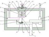
FIG. 1 is a schematic view of the overall structure of the present invention;
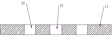
FIG. 2 is a schematic view of a first slide plate according to the present invention;
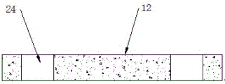
fig. 3 is a schematic structural view of a second slide plate of the present invention.
In the figure: 1. a housing; 2. a ceramic heat conducting block; 3. a conductive plate; 4. static contact; 5. an insulating plate; 6. a bimetal; 7. a moving contact; 8. a conductive block; 9. a fuse; 10. a T-shaped rod; 11. a first slide plate; 12. a second slide plate; 13. a threaded rod; 14. turning a handle; 15. a connecting plate; 16. a connecting rod; 17. a vertical rod; 18. a T-shaped limiting groove; 19. a T-shaped limiting block; 20. a positive conductive line; 21. a negative conductive wire; 22. a first slide hole; 23. a second slide hole; 24. a third slide hole; 25. a threaded hole; 26. a fourth slide hole; 27. a spring.
Detailed Description
The technical solutions in the embodiments of the present invention will be described clearly and completely with reference to the accompanying drawings in the embodiments of the present invention, and it is obvious that the described embodiments are only some embodiments of the present invention, not all embodiments. Based on the embodiments in the present invention, all other embodiments obtained by a person skilled in the art without creative work belong to the protection scope of the present invention.
Examples
Referring to fig. 1-3, the present invention provides the following technical solutions: a novel temperature controller with an overheat protection function comprises a shell 1, a ceramic heat conduction block 2 is fixedly penetrated through the bottom of the shell 1, a current conducting plate 3 is fixedly arranged on one side wall of the shell 1, a fixed contact 4 is fixedly arranged at the bottom of one end of the current conducting plate 3, an insulating plate 5 is fixedly arranged on the other side wall of the shell 1, a bimetallic strip 6 is fixedly arranged at the bottom of one end of the insulating plate 5, the bottom of the bimetallic strip 6 is fixedly connected with the top of the ceramic heat conduction block 2, a movable contact 7 is fixedly arranged at the top of one end of the bimetallic strip 6, the movable contact 7 is tightly contacted with the fixed contact 4, a conductive block 8 is fixedly penetrated through one end of the insulating plate 5, a fuse 9 is fixedly arranged on one side wall of the conductive block 8, one end, far away from the conductive block 8, of the fuse 9 is fixedly connected with one side wall of the bimetallic strip 6, two T-shaped rods 10, the first sliding plate 11 and the second sliding plate 12 are both connected to the outer side wall of the T-shaped rod 10 in a sliding manner, the top of the shell 1 is rotatably connected with a threaded rod 13 through a bearing, the top of the threaded rod 13 is fixed with a rotating handle 14, the outer side wall of the threaded rod 13 is sleeved with a connecting plate 15, the threaded rod 13 is in threaded connection with the connecting plate 15, the bottom of the connecting plate 15 is symmetrically fixed with connecting rods 16, the bottom ends of the connecting rods 16 are both slidably connected with the top of the first sliding plate 11 through the inner wall of the top of the shell 1, the bottom of the second sliding plate 12 is fixed with a vertical rod 17, the bottom end of the vertical rod 17 slidably passes through the bottom of the first sliding plate 11, the outer side of the vertical rod 17 is sleeved with a spring 27, two ends of the spring 27 are respectively fixedly connected with the top of the first sliding plate 11 and the bottom of the second sliding plate, the bottom end of the vertical rod 17 is rotatably connected with the top of the T-shaped limiting block 19 through a pin, the top of the conductive plate 3 is fixed with an anode conductive wire 20, the top of the conductive block 8 is fixed with a cathode conductive wire 21, and one end of each of the anode conductive wire 20 and the cathode conductive wire 21 penetrates through the top of the shell 1.
In this embodiment, through set up fuse 9 between bimetallic strip 6 and conducting block 8, break down when bimetallic strip 6, be heated when unable emergence deformation, when the temperature of equipment is too high, fuse 9 is under the high temperature effect, can break off, thereby play open circuit's effect, so can play overheat protection's effect, through setting up T type pole 10, first slide 11, second slide 12, threaded rod 13, change 14, connecting plate 15, connecting rod 16 and montant 17, can realize regulating spring 27's elastic potential energy, thereby can adjust the scope of temperature disconnection, and the operation is comparatively simple.
Specifically, the top of the first sliding plate 11 is symmetrically provided with first sliding holes 22, the T-shaped rods 10 respectively penetrate through the corresponding first sliding holes 22, the top of the first sliding plate 11 is provided with second sliding holes 23, and the vertical rods 17 penetrate through the second sliding holes 23.
In this embodiment, the first slide holes 22 are symmetrically formed at the top of the first slide plate 11 in order to allow the T-bar 10 to smoothly pass through the first slide plate 11, thereby making the first slide plate 11 more stable during movement, and the second slide holes 23 are formed at the top of the first slide plate 11 in order to allow the vertical bars 17 to smoothly pass through the first slide plate 11.
Specifically, the top of the second sliding plate 12 is symmetrically provided with third sliding holes 24, and the T-shaped rods 10 respectively penetrate through the corresponding third sliding holes 24.
In this embodiment, the third slide holes 24 are symmetrically formed at the top of the second slide plate 12, so that the T-bar 10 can smoothly penetrate through the second slide plate 12, and the second slide plate 12 can be moved more stably.
Specifically, the surface of the rotating handle 14 is provided with anti-slip lines.
In this embodiment, the anti-slip pattern is disposed on the surface of the rotating handle 14, so that the rotating handle 14 can be rotated conveniently.
Specifically, a threaded hole 25 is formed in the top of the connecting plate 15, and the threaded rod 13 is in threaded connection with the threaded hole 25.
In this embodiment, the top of the connecting plate 15 is provided with a threaded hole 25 for cooperating with the threaded rod 13, so that the connecting plate 15 can be driven to move when the threaded rod 13 rotates.
Specifically, a fourth sliding hole 26 is formed at the top of the housing 1, and the connecting rod 16 penetrates through the corresponding fourth sliding hole 26.
In the present embodiment, the fourth slide hole 26 is opened at the top of the housing 1, so that the connecting rod 16 can smoothly pass through the top inner wall of the housing 1.
The utility model discloses a theory of operation and use flow: initially, the fixed contact 7 and the movable contact 4 are in contact, the ceramic heat conducting block 2 is fixed at a temperature measuring position of the equipment, the ceramic heat conducting block 2 transfers heat to the bimetallic strip 6, when the temperature reaches a set value, the bimetallic strip 6 is heated and bent downwards, so that the movable contact 7 and the fixed contact 4 can be separated, a circuit is disconnected, the equipment stops working, when the bimetallic strip 6 is bent downwards, the vertical rod 17 is driven to move downwards, so that the second sliding plate 12 can be driven to move downwards, the spring 27 can be compressed, if the temperature needs to be raised, the rotating handle 14 can be rotated, the rotating handle 14 drives the threaded rod 13 to rotate, the threaded rod 13 drives the connecting plate 15 to move upwards, the connecting plate 15 drives the connecting rod 16 to move upwards, the connecting rod 16 drives the first sliding plate 11 to move upwards, so that the spring 27 can be compressed, and the elastic potential energy of the spring 27 becomes large, the bimetallic strip 6 can be bent downwards, so that the circuit can be disconnected, namely, when the bimetallic strip 6 breaks down, the bimetallic strip cannot be heated and bent, the circuit cannot be disconnected, and when the temperature of the temperature measuring part of the equipment is too high, the fuse 9 can be disconnected due to the too high temperature, so that the circuit can be disconnected, and the overheat protection effect is achieved.
Finally, it should be noted that: although the present invention has been described in detail with reference to the foregoing embodiments, it will be apparent to those skilled in the art that modifications may be made to the embodiments described in the foregoing embodiments, or equivalents may be substituted for elements thereof. Any modification, equivalent replacement, or improvement made within the spirit and principle of the present invention should be included in the protection scope of the present invention.
Claims (6)
1. The utility model provides a novel temperature controller with overheat protection function, includes casing (1), its characterized in that: the bottom of the shell (1) is fixedly provided with a ceramic heat conducting block (2) in a penetrating manner, one side wall of the shell (1) is fixedly provided with a conductive plate (3), one end of the conductive plate (3) is fixedly provided with a fixed contact (4), the other side wall of the shell (1) is fixedly provided with an insulating plate (5), one end of the insulating plate (5) is fixedly provided with a bimetallic strip (6), the bottom of the bimetallic strip (6) is fixedly connected with the top of the ceramic heat conducting block (2), one end of the bimetallic strip (6) is fixedly provided with a movable contact (7), the movable contact (7) is tightly contacted with the fixed contact (4), one end of the insulating plate (5) is fixedly provided with a conductive block (8) in a penetrating manner, one side wall of the conductive block (8) is fixedly provided with a fuse (9), one end of the fuse (9), which is far away from the conductive block (8), is fixedly connected with one side, the top inner wall of casing (1) is fixed with two T type poles (10), the inside of casing (1) is provided with first slide (11) and second slide (12) respectively, equal sliding connection in the lateral wall of T type pole (10) of first slide (11) and second slide (12), the top of casing (1) is rotated through the bearing and is connected with threaded rod (13), the top of threaded rod (13) is fixed with commentaries on classics handle (14), the lateral wall cover of threaded rod (13) is equipped with connecting plate (15), and threaded rod (13) and connecting plate (15) pass through threaded connection, the bottom symmetry of connecting plate (15) is fixed with connecting rod (16), the bottom of connecting rod (16) all slides the top inner wall that passes casing (1) and the top fixed connection of first slide (11), the bottom of second slide (12) is fixed with montant (17), the bottom of first slide (11) is passed in the bottom slip of montant (17), the outside cover of montant (17) is equipped with spring (27), the both ends of spring (27) respectively with the top of first slide (11) and the bottom fixed connection of second slide (12), T type spacing groove (18) have been seted up at the top of bimetallic strip (6), the inside sliding connection of T type spacing groove (18) has T type stopper (19), the bottom of montant (17) is passed through the pin and is connected with the top rotation of T type stopper (19), the top of current conducting plate (3) is fixed with anodal conductor wire (20), the top of current conducting block (8) is fixed with negative pole conductor wire (21), the top of casing (1) is all run through to the one end of anodal conductor wire (20) and negative pole conductor wire (21).
2. The novel temperature controller with overheat protection function according to claim 1, wherein: first slide opening (22) have been seted up to the top symmetry of first slide (11), corresponding first slide opening (22) are run through respectively to T type pole (10), second slide opening (23) have been seted up at the top of first slide (11), montant (17) run through second slide opening (23).
3. The novel temperature controller with overheat protection function according to claim 1, wherein: third sliding holes (24) are symmetrically formed in the top of the second sliding plate (12), and the T-shaped rods (10) penetrate through the corresponding third sliding holes (24) respectively.
4. The novel temperature controller with overheat protection function according to claim 1, wherein: the surface of the rotating handle (14) is provided with anti-skid grains.
5. The novel temperature controller with overheat protection function according to claim 1, wherein: the top of the connecting plate (15) is provided with a threaded hole (25), and the threaded rod (13) is in threaded connection with the threaded hole (25).
6. The novel temperature controller with overheat protection function according to claim 1, wherein: the top of the shell (1) is provided with a fourth sliding hole (26), and the connecting rod (16) penetrates through the corresponding fourth sliding hole (26).
Priority Applications (1)
| Application Number | Priority Date | Filing Date | Title |
|---|---|---|---|
| CN201921318877.XU CN210223894U (en) | 2019-08-15 | 2019-08-15 | Novel temperature controller with overheat protection function |
Applications Claiming Priority (1)
| Application Number | Priority Date | Filing Date | Title |
|---|---|---|---|
| CN201921318877.XU CN210223894U (en) | 2019-08-15 | 2019-08-15 | Novel temperature controller with overheat protection function |
Publications (1)
| Publication Number | Publication Date |
|---|---|
| CN210223894U true CN210223894U (en) | 2020-03-31 |
Family
ID=69918533
Family Applications (1)
| Application Number | Title | Priority Date | Filing Date |
|---|---|---|---|
| CN201921318877.XU Active CN210223894U (en) | 2019-08-15 | 2019-08-15 | Novel temperature controller with overheat protection function |
Country Status (1)
| Country | Link |
|---|---|
| CN (1) | CN210223894U (en) |
Cited By (10)
| Publication number | Priority date | Publication date | Assignee | Title |
|---|---|---|---|---|
| CN111710558A (en) * | 2020-06-17 | 2020-09-25 | 湖北宏源电力设计咨询有限公司 | Apparatus and method for protecting low-voltage circuits |
| CN112000152A (en) * | 2020-08-11 | 2020-11-27 | 慈溪市凯达温控器有限公司 | Novel temperature controller |
| CN112466711A (en) * | 2020-11-30 | 2021-03-09 | 江苏金鑫信息技术有限公司 | Combined adjustable temperature control switch applied to electronic equipment and use method thereof |
| CN112582207A (en) * | 2020-12-21 | 2021-03-30 | 合肥舒实工贸有限公司 | Temperature controller and mounting bracket thereof |
| CN114188186A (en) * | 2021-12-14 | 2022-03-15 | 扬州五岳电器有限公司 | Power-off reset temperature control switch |
| CN114188183A (en) * | 2021-12-06 | 2022-03-15 | 宝应安的电子技术有限公司 | High-temperature circuit-breaking protection temperature controller |
| CN115173350A (en) * | 2022-06-11 | 2022-10-11 | 东营市南方电器有限责任公司 | Strain clamp for electric power engineering |
| WO2023020584A1 (en) * | 2021-08-18 | 2023-02-23 | 厦门赛尔特电子有限公司 | Thermal fuse |
| CN116712704A (en) * | 2023-06-05 | 2023-09-08 | 江苏荣夏安全科技有限公司 | Overload monitoring system for fire-fighting equipment |
| CN118919356A (en) * | 2024-07-18 | 2024-11-08 | 合肥中科君达视界技术股份有限公司 | Self-adaptive temperature regulation protection device |
-
2019
- 2019-08-15 CN CN201921318877.XU patent/CN210223894U/en active Active
Cited By (15)
| Publication number | Priority date | Publication date | Assignee | Title |
|---|---|---|---|---|
| CN111710558A (en) * | 2020-06-17 | 2020-09-25 | 湖北宏源电力设计咨询有限公司 | Apparatus and method for protecting low-voltage circuits |
| CN112000152A (en) * | 2020-08-11 | 2020-11-27 | 慈溪市凯达温控器有限公司 | Novel temperature controller |
| CN112466711A (en) * | 2020-11-30 | 2021-03-09 | 江苏金鑫信息技术有限公司 | Combined adjustable temperature control switch applied to electronic equipment and use method thereof |
| CN112582207B (en) * | 2020-12-21 | 2024-03-08 | 合肥舒实工贸有限公司 | Temperature controller and mounting bracket thereof |
| CN112582207A (en) * | 2020-12-21 | 2021-03-30 | 合肥舒实工贸有限公司 | Temperature controller and mounting bracket thereof |
| WO2023020584A1 (en) * | 2021-08-18 | 2023-02-23 | 厦门赛尔特电子有限公司 | Thermal fuse |
| CN114188183A (en) * | 2021-12-06 | 2022-03-15 | 宝应安的电子技术有限公司 | High-temperature circuit-breaking protection temperature controller |
| CN114188186A (en) * | 2021-12-14 | 2022-03-15 | 扬州五岳电器有限公司 | Power-off reset temperature control switch |
| CN114188186B (en) * | 2021-12-14 | 2024-05-28 | 扬州五岳电器有限公司 | Power-off reset temperature control switch |
| CN115173350A (en) * | 2022-06-11 | 2022-10-11 | 东营市南方电器有限责任公司 | Strain clamp for electric power engineering |
| CN115173350B (en) * | 2022-06-11 | 2023-08-15 | 东营市南方电器有限责任公司 | Tension clamp for electric power engineering |
| CN116712704A (en) * | 2023-06-05 | 2023-09-08 | 江苏荣夏安全科技有限公司 | Overload monitoring system for fire-fighting equipment |
| CN116712704B (en) * | 2023-06-05 | 2025-07-15 | 江苏荣夏安全科技有限公司 | Overload monitoring system for fire-fighting equipment |
| CN118919356A (en) * | 2024-07-18 | 2024-11-08 | 合肥中科君达视界技术股份有限公司 | Self-adaptive temperature regulation protection device |
| CN118919356B (en) * | 2024-07-18 | 2025-10-24 | 合肥中科君达视界技术股份有限公司 | An adaptive temperature regulating protection device |
Similar Documents
| Publication | Publication Date | Title |
|---|---|---|
| CN210200630U (en) | Novel temperature controller capable of conducting heat rapidly | |
| CN112531423A (en) | High temperature row of inserting is prevented in intelligence outage | |
| US11469064B2 (en) | Flash double-temperature linkage temperature controller | |
| CN203205341U (en) | Kicking thermostat | |
| CN201233840Y (en) | Sudden skip temperature controller | |
| CN217588802U (en) | Temperature controller with overheat protection structure | |
| CN203826287U (en) | Thermistor three-pole temperature controller | |
| CN210815176U (en) | Automatic temperature control reaction kettle for producing 3, 5-dichlorobenzoyl chloride | |
| CN204332830U (en) | The reset bimetallic temperature controller that a kind of high temperature resistant sensitivity is adjustable | |
| CN206532747U (en) | An overheating and overcurrent power failure protection device | |
| CN108526646A (en) | Energy-saving anti-scalding Intelligent electric iron | |
| CN212434539U (en) | A kind of thermal insulation adjustable temperature control equipment | |
| CN214411093U (en) | Automatic intelligent power-off device for power production operation fault | |
| CN111312560A (en) | Overload overtemperature power failure self-recovery protector for household appliances | |
| CN216818209U (en) | a temperature switch | |
| CN206350340U (en) | A kind of temperature control storehouse preserved for crisp Lee | |
| CN208861894U (en) | A kind of bipolar high current temperature limiter | |
| CN208706539U (en) | A kind of bipolar high current temperature controller with manual reset | |
| CN211125496U (en) | Flashing type double-channel control temperature controller | |
| CN201927546U (en) | Thermostatic type temperature controller | |
| CN209045432U (en) | A kind of power-off restoration temperature controller | |
| CN219329217U (en) | Household appliance temperature controller capable of realizing fire and heat protection | |
| CN222848384U (en) | Cooling fans and cooking utensils | |
| CN214043532U (en) | Temperature controller with heating protection device | |
| US2549532A (en) | Thermal and manual snap-action circuit breaker |
Legal Events
| Date | Code | Title | Description |
|---|---|---|---|
| GR01 | Patent grant | ||
| GR01 | Patent grant |