CN210214866U - Solid-liquid separation device for wastewater treatment - Google Patents
Solid-liquid separation device for wastewater treatment Download PDFInfo
- Publication number
- CN210214866U CN210214866U CN201920703412.XU CN201920703412U CN210214866U CN 210214866 U CN210214866 U CN 210214866U CN 201920703412 U CN201920703412 U CN 201920703412U CN 210214866 U CN210214866 U CN 210214866U
- Authority
- CN
- China
- Prior art keywords
- shell
- solid
- liquid separation
- cylindrical shell
- pipe
- Prior art date
- Legal status (The legal status is an assumption and is not a legal conclusion. Google has not performed a legal analysis and makes no representation as to the accuracy of the status listed.)
- Active
Links
- 238000000926 separation method Methods 0.000 title claims abstract description 31
- 239000007788 liquid Substances 0.000 title claims abstract description 30
- 238000004065 wastewater treatment Methods 0.000 title claims abstract description 7
- 239000012535 impurity Substances 0.000 claims abstract description 18
- XLYOFNOQVPJJNP-UHFFFAOYSA-N water Substances O XLYOFNOQVPJJNP-UHFFFAOYSA-N 0.000 claims description 59
- 238000005188 flotation Methods 0.000 claims description 14
- 239000000463 material Substances 0.000 claims description 13
- 239000002893 slag Substances 0.000 claims description 9
- 238000005192 partition Methods 0.000 claims description 4
- 239000002351 wastewater Substances 0.000 abstract description 15
- 230000000694 effects Effects 0.000 abstract description 13
- 238000001914 filtration Methods 0.000 abstract description 9
- 238000001556 precipitation Methods 0.000 abstract description 2
- 239000003818 cinder Substances 0.000 abstract 2
- 239000003921 oil Substances 0.000 description 20
- 239000000945 filler Substances 0.000 description 5
- 239000012530 fluid Substances 0.000 description 5
- 239000010842 industrial wastewater Substances 0.000 description 5
- 238000000034 method Methods 0.000 description 5
- 230000008569 process Effects 0.000 description 4
- 238000004519 manufacturing process Methods 0.000 description 3
- 239000013049 sediment Substances 0.000 description 3
- 241000237942 Conidae Species 0.000 description 2
- 241000758789 Juglans Species 0.000 description 2
- 235000009496 Juglans regia Nutrition 0.000 description 2
- 239000006004 Quartz sand Substances 0.000 description 2
- VYPSYNLAJGMNEJ-UHFFFAOYSA-N Silicium dioxide Chemical compound O=[Si]=O VYPSYNLAJGMNEJ-UHFFFAOYSA-N 0.000 description 2
- 238000007599 discharging Methods 0.000 description 2
- 238000000605 extraction Methods 0.000 description 2
- 239000007789 gas Substances 0.000 description 2
- 238000009776 industrial production Methods 0.000 description 2
- 230000005012 migration Effects 0.000 description 2
- 238000013508 migration Methods 0.000 description 2
- 239000010813 municipal solid waste Substances 0.000 description 2
- 239000002245 particle Substances 0.000 description 2
- 238000004062 sedimentation Methods 0.000 description 2
- 239000010802 sludge Substances 0.000 description 2
- 239000007787 solid Substances 0.000 description 2
- 229910001220 stainless steel Inorganic materials 0.000 description 2
- 239000010935 stainless steel Substances 0.000 description 2
- 239000000126 substance Substances 0.000 description 2
- 235000020234 walnut Nutrition 0.000 description 2
- 241000282414 Homo sapiens Species 0.000 description 1
- 239000004743 Polypropylene Substances 0.000 description 1
- CVTZKFWZDBJAHE-UHFFFAOYSA-N [N].N Chemical class [N].N CVTZKFWZDBJAHE-UHFFFAOYSA-N 0.000 description 1
- 230000009471 action Effects 0.000 description 1
- 239000006227 byproduct Substances 0.000 description 1
- 239000000919 ceramic Substances 0.000 description 1
- 230000008859 change Effects 0.000 description 1
- 239000002131 composite material Substances 0.000 description 1
- 230000007423 decrease Effects 0.000 description 1
- 238000013461 design Methods 0.000 description 1
- 238000011161 development Methods 0.000 description 1
- 238000005516 engineering process Methods 0.000 description 1
- 239000003344 environmental pollutant Substances 0.000 description 1
- 238000003912 environmental pollution Methods 0.000 description 1
- 239000000835 fiber Substances 0.000 description 1
- 238000005189 flocculation Methods 0.000 description 1
- 230000016615 flocculation Effects 0.000 description 1
- 230000036541 health Effects 0.000 description 1
- 229910001385 heavy metal Inorganic materials 0.000 description 1
- 230000006872 improvement Effects 0.000 description 1
- 239000008235 industrial water Substances 0.000 description 1
- 238000009434 installation Methods 0.000 description 1
- 239000013067 intermediate product Substances 0.000 description 1
- 150000002500 ions Chemical class 0.000 description 1
- 244000005700 microbiome Species 0.000 description 1
- 231100000719 pollutant Toxicity 0.000 description 1
- -1 polypropylene Polymers 0.000 description 1
- 229920001155 polypropylene Polymers 0.000 description 1
- 238000012545 processing Methods 0.000 description 1
- 239000000047 product Substances 0.000 description 1
- 239000010865 sewage Substances 0.000 description 1
- 231100000331 toxic Toxicity 0.000 description 1
- 230000002588 toxic effect Effects 0.000 description 1
- 239000002699 waste material Substances 0.000 description 1
- 238000003466 welding Methods 0.000 description 1
Images
Landscapes
- Physical Water Treatments (AREA)
Abstract
The utility model particularly relates to a solid-liquid separation equipment for waste water treatment, this solid-liquid separation equipment includes the barrel, go up lid and the whirl air supporting subassembly of setting in the barrel inside, the connection can be dismantled to barrel and last lid, whirl air supporting subassembly is including arranging oil pipe, the back taper shell, first cylinder shell, second cylinder shell, the toper shell, arrange miscellaneous pipe, first inlet tube, baffle under second inlet tube and the V-arrangement, the bottom of baffle is provided with row cinder notch under the V-arrangement, the side of baffle is provided with the mud collection fill under the V-arrangement, arrange miscellaneous bottom of pipe and pass row cinder notch and carry out row impurity, the top of lid is passed at the top of arranging oil pipe arranges oil, upward be provided with the outlet on the lid. The utility model discloses a solid-liquid separation device carries out whirl, separation, filtration and precipitation to the waste water that gets into in the barrel, finally realizes solid-liquid separation, and the settling velocity is fast, and the treatment effect is good, and convenient operation.
Description
Technical Field
The utility model belongs to the waste water treatment field, concretely relates to a solid-liquid separation equipment for waste water treatment.
Background
With the improvement of living standard and the progress of modern science and technology, the industrial field is well developed, various products with high quality and excellent performance emerge endlessly, water is an indispensable resource, more and more industrial water is used, the produced industrial wastewater contains various suspended substances, solid particles, oils, heavy metal ions, ammonia nitrogen compounds, microorganisms, toxic and nonbiodegradable organic matters and the like, and if the industrial wastewater is directly discharged into nature, the environmental pollution is inevitably caused, so the wastewater can be discharged after being treated.
Industrial waste water including production waste water and production sewage refers to waste water and waste liquid produced in industrial production process, which contains industrial production materials, intermediate products, byproducts and pollutants produced in the production process, which are lost along with water, along with the rapid development of industry, the types and the amount of waste water are rapidly increased, the pollution to water is also gradually wide and serious, and the health and the safety of human beings are threatened.
The existing solid-liquid separation device for most industrial wastewater has larger volume, and most of the existing solid-liquid separation devices are difficult to take out solid garbage in the industrial wastewater after being used, so that the treatment effect is poor, the sedimentation speed is slow, more inconvenience exists in the operation process, and the situation of incomplete solid-liquid separation also occurs.
SUMMERY OF THE UTILITY MODEL
In order to solve the poor problem of treatment effect that exists among the prior art, the utility model provides a solid-liquid separation equipment for waste water treatment, this solid-liquid separation equipment carries out whirl, separation, filtration and sediment to the waste water that gets into, finally realizes solid-liquid separation, and the treatment effect is good. The to-be-solved technical problem of the utility model is realized through following technical scheme:
a solid-liquid separation device comprises a cylinder body, an upper cover body and a rotational flow air flotation assembly arranged in the cylinder body, wherein the cylinder body is detachably connected with the upper cover body;
the rotational flow air flotation assembly comprises an oil discharge pipe, an inverted conical shell, a first cylindrical shell, a second cylindrical shell, a conical shell, an impurity discharge pipe, a first water inlet pipe, a second water inlet pipe and a V-shaped lower baffle;
the top of the inverted cone-shaped shell is fixed and communicated with the bottom of the oil discharge pipe, the bottom of the inverted cone-shaped shell is fixedly connected with a first cylindrical shell, the top of the conical shell is fixedly connected with a second cylindrical shell, the bottom of the conical shell is fixed and communicated with the top of the impurity discharge pipe, and the first cylindrical shell is sleeved on the outer side of the second cylindrical shell;
the first water inlet pipe and the second water inlet pipe transversely penetrate through the first cylindrical shell and the second cylindrical shell, and the end parts of the first water inlet pipe and the second water inlet pipe are both in a spiral line type structure;
the bottom of the V-shaped lower baffle is provided with a slag discharge port, the side surface of the V-shaped lower baffle is provided with a sludge collecting hopper, and the bottom of the impurity discharge pipe penetrates through the slag discharge port to discharge impurities;
the top of oil extraction pipe passes the top of upper cover body and carries out the oil extraction, be provided with the outlet on the upper cover body.
Furthermore, an annular support frame is fixed outside the first cylindrical shell, an annular screen shell made of a screen mesh is fixed on the annular support frame, and a filter material is filled in the screen shell.
Further, the difference between the outer diameter and the inner diameter of the screen shell is equal to the distance between the inner wall of the cylinder and the outer wall of the first cylindrical shell.
Further, a feeding hole and a discharging hole are formed in the screen shell, and the feeding hole and the discharging hole penetrate through the side wall of the cylinder body.
Further, a partition plate for isolating fine impurities is fixed to the outside of the first cylindrical shell.
Further, the top of the oil discharge pipe is communicated with a pressure reducing valve.
Further, the upper cover body and the cylinder body are fixedly connected through screws.
The utility model has the advantages that:
the utility model discloses a solid-liquid separation device is provided with whirl air supporting subassembly inside the barrel, can carry out whirl, separation, filtration and sediment to the waste water that gets into in the barrel, finally realizes solid-liquid separation, and the settling velocity is fast, and the treatment effect is good, and convenient operation.
The present invention will be described in further detail with reference to the accompanying drawings and examples.
Drawings
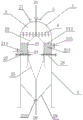
FIG. 1 is a schematic view of the structure of a solid-liquid separation apparatus according to this embodiment.
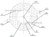
FIG. 2 is a bottom view of the solid-liquid separator of this embodiment.
In the figure: 1. a rotational flow air flotation unit; 21. an oil discharge pipe; 22. an inverted conical shell; 23. a first cylindrical shell; 24. a second cylindrical shell; 25. a conical shell; 26. a trash removal pipe; 27. a first water inlet pipe; 28. a second water inlet pipe; 29. a V-shaped lower baffle; 210. a slag discharge port; 212. a screen shell; 213. filtering the material; 214. a feed inlet; 215. a discharge port; 3. an upper cover body; 31. a water outlet; 4. a barrel; 5. a pressure reducing valve; 6. and (4) screws.
Detailed Description
To further illustrate the technical means and effects of the present invention adopted to achieve the predetermined purpose, the following detailed description of the embodiments, structural features and effects of the present invention will be made with reference to the accompanying drawings and examples.
In the description of the present embodiments, it is to be understood that the terms "center", "longitudinal", "lateral", "up", "down", "front", "back", "left", "right", "vertical", "horizontal", "top", "bottom", "inner", "outer", etc. indicate orientations or positional relationships based on those shown in the drawings, and are only for convenience of describing the present invention and simplifying the description, but do not indicate or imply that the device or element referred to must have a particular orientation, be constructed and operated in a particular orientation, and thus, should not be construed as limiting the present invention.
Furthermore, the terms "first," "second," "third," and the like are used for descriptive purposes only and are not to be construed as indicating or implying relative importance or implicit to a number of indicated technical features. Thus, a feature defined as "first," "second," etc. may explicitly or implicitly include one or more of that feature. In the description of the invention, the meaning of "a plurality" is two or more unless otherwise specified.
The terms "mounted," "connected," and "coupled" are to be construed broadly and may, for example, be fixedly coupled, detachably coupled, or integrally coupled; can be mechanically or electrically connected; they may be connected directly or indirectly through intervening media, or they may be interconnected between two elements. The specific meaning of the above terms in the creation of the present invention can be understood by those of ordinary skill in the art through specific situations.
Referring to fig. 1 and 2, the solid-liquid separation apparatus of the present embodiment includes a cylinder 4, an upper cover 3, and a cyclone air-flotation assembly disposed inside the cylinder 4, wherein the cylinder 4 and the upper cover 3 are detachably connected. The cylinder 4 and the upper cover 3 of the present embodiment are made of stainless steel, and the upper cover 3 and the cylinder 4 are fixedly connected by screws 6.
The cyclone air flotation assembly comprises an oil discharge pipe 21, an inverted conical shell 22, a first cylindrical shell 23, a second cylindrical shell 24, a conical shell 25, an impurity discharge pipe 26, a first water inlet pipe 27, a second water inlet pipe 28 and a V-shaped lower baffle plate 29. The top of the inverted cone shell 22 is fixed and communicated with the bottom of the oil discharge pipe 21, the bottom of the inverted cone shell 22 is fixedly connected with the first cylindrical shell 23, the top of the conical shell 25 is fixedly connected with the second cylindrical shell 24, the bottom of the conical shell 25 is fixed and communicated with the top of the impurity discharge pipe 26, and the first cylindrical shell 23 is sleeved on the outer side of the second cylindrical shell 24. The rotational flow air flotation component is formed by processing stainless steel, so parts are fixed by welding.
The first water inlet pipe 27 and the second water inlet pipe 28 transversely penetrate through the first cylindrical shell 23 and the second cylindrical shell 24, the end parts of the first water inlet pipe 27 and the second water inlet pipe 28 are both in a spiral line type structure, and the turbulence and the disturbance degree of fluid at the water inlet can be weakened through the water inlet pipes with the sections, so that the energy loss in the cylinder body is reduced. The wastewater enters from the first water inlet pipe 27 and the second water inlet pipe 28 of the rotational flow air flotation unit at the same time, and the wastewater enters the rotational flow air flotation unit to generate rotational flow effect. The waste water enters the cylinder body along the tangential inlet at a certain speed, and rotates towards the center while moving downwards under the limit of the inner wall, namely, the waste water is subjected to outer rotational flow; due to the suction of the low pressure at the center of the cylinder and the space limitation of the conical section, the internal fluid rotates upwards to make a rotary motion, namely, an internal rotational flow. As the flow radius decreases, the pressure energy is gradually converted into fluid kinetic energy and energy loss. The waste water is subjected to centrifugal inertia force, centripetal buoyancy force and fluid resistance in the cylinder body, and the 3 forces promote the substances with different densities to be orderly separated in the cylinder body.
Because the density difference of oil, water, gas, sediment etc. under the effect of centrifugal force, the material that density is bigger than water is got rid of on the inner wall of toper shell, discharges from row's miscellaneous mouthful at last, and oil, gas, water are compelled to central zone migration, and tiny bubble carries out oil, the flocculation in the migration in-process in aqueous to realize the enrichment in the central zone of back taper shell, at last through oil outlet pipe, with oil and floc discharge system. Because the oil and the floc are removed under the combined action of air flotation and rotational flow, the treatment time is greatly shortened, the treatment capacity of the equipment is increased, and particularly when the water quality is seriously deteriorated, the equipment can realize quick treatment, thereby achieving the purposes of moderate abundance and double processes.
After a large amount of oil and flocs are removed, the wastewater quickly flows into the upper area of the V-shaped lower baffle from the gap between the first cylindrical shell and the second cylindrical shell, and the water flow speed is quickly reduced due to the volume change of the area, so that the wastewater is very suitable for precipitation and filtration. Therefore, a filtering zone is designed in the upper part of this zone. The slag generated in the filtering area is discharged from the slag discharge port, and the treated water enters the inverted cone-shaped shell and the upper part of the filtering area to form a clear water area and is finally discharged from the water discharge port.
The ratio of the height of the rotational flow air flotation unit to the diameter of the cylinder body is 1.7, the diameters of the first water inlet pipe and the second water inlet pipe are 0.25-0.4 times of the diameter of the cylinder body, and the water inlet speed of the first water inlet pipe and the second water inlet pipe is generally 1-2 m/s.
The bottom of the V-shaped lower baffle plate 29 is provided with a slag discharge port 210, the side surface of the V-shaped lower baffle plate 29 is provided with a sludge collecting hopper, and the bottom of the impurity discharge pipe 26 penetrates through the slag discharge port 210 to discharge impurities. The top of the oil drain pipe 21 penetrates the top of the upper cover 3 to drain oil, and the upper cover 3 is provided with a water outlet 31. The top of the drain pipe 21 communicates with the pressure reducing valve 5.
In order to further improve the solid-liquid separation effect and separate fine impurities, an annular support frame is fixed outside the first cylindrical shell 23 of the solid-liquid separation system of the present embodiment, an annular screen shell 212 made of a screen mesh is fixed on the annular support frame, and the screen shell 212 is filled with a filter material 213. The difference between the outer diameter and the inner diameter of the screen shell 212 is equal to the distance between the inner wall of the cylinder 4 and the outer wall of the first cylindrical shell 23. The screen shell 212 is provided with a feed port 214 and a discharge port 215, and the feed port 214 and the discharge port 215 penetrate through the side wall of the cylinder 4.
In order to further improve the solid-liquid separation effect, the fine impurities can also be separated in the form of a partition plate. An annular support frame is fixed outside the first cylindrical shell 23, and a partition plate for isolating fine impurities is fixed on the annular support frame.
In order to improve the filtering effect, the filler can be flexibly selected according to the water quality of inlet water and the water outlet requirement. When the oil content in the inlet water is higher, the conglomerate filler with high-efficiency oil-removing effect is preferably selected, such as polypropylene corrugated plate, ceramic corrugation, ceramsite filler and the like; when the content of suspended matters in the inlet water is high, inclined plates, inclined tube fillers and the like for accelerating the sedimentation of the suspended matters can be selected; when the oil and suspended matters in the water are high, walnut shells, quartz sand and other filter materials can be selected to meet the water outlet requirement.
When the fluctuation of the inflow water is large, especially when the actual treatment capacity is less than the designed treatment capacity, the wastewater entering the rotational flow air flotation reactor cannot reach the flow rate required by the rotational flow or the amount of flocs in the effluent of the reactor is large, the buffer area has the functions of reducing the flow rate of the water body and increasing the settling time of the water body, and the outlet water quality of the system is still ensured by the principle of a shallow pool behind an inclined plate (pipe).
In the field operation process, the installation position of the rotational flow air flotation system in the whole process can be flexibly selected, and the property of the filler can be determined. When the composite material is used as a pretreatment device of a water treatment system, an inclined plate (pipe) or a coarse grained material can be selected to correspond to high-oil-content produced water and fracturing flow-back fluid, so that the rear-end load is reduced. When the filter material is used as a fine treatment device of a water treatment system, the walnut shell, the modified fiber balls, the quartz sand, the active filter material and other filter materials can be selected to correspond to the water quality of high suspended matters, so that the concentration of suspended matters in the water quality and the median of the particle size are reduced. The coarse grained material is an oleophilic material, the relative density is more than 1, and the grain size is preferably 3-5 mm, such as ceramsite and the like.
The foregoing is a more detailed description of the present invention, taken in conjunction with the specific preferred embodiments thereof, and it is not intended that the invention be limited to the specific embodiments shown and described. To the utility model belongs to the technical field of ordinary technical personnel, do not deviate from the utility model discloses under the prerequisite of design, can also make a plurality of simple deductions or replacement, all should regard as belonging to the utility model discloses a protection scope.
Claims (7)
1. A solid-liquid separation equipment for waste water treatment which characterized in that: the cyclone air flotation device comprises a cylinder body (4), an upper cover body (3) and a cyclone air flotation assembly arranged inside the cylinder body (4), wherein the cylinder body (4) is detachably connected with the upper cover body (3);
the cyclone air floatation assembly comprises an oil discharge pipe (21), an inverted conical shell (22), a first cylindrical shell (23), a second cylindrical shell (24), a conical shell (25), an impurity discharge pipe (26), a first water inlet pipe (27), a second water inlet pipe (28) and a V-shaped lower baffle plate (29);
the top of the inverted cone-shaped shell (22) is fixed and communicated with the bottom of the oil discharge pipe (21), the bottom of the inverted cone-shaped shell (22) is fixedly connected with the first cylindrical shell (23), the top of the cone-shaped shell (25) is fixedly connected with the second cylindrical shell (24), the bottom of the cone-shaped shell (25) is fixed and communicated with the top of the impurity discharge pipe (26), and the first cylindrical shell (23) is sleeved on the outer side of the second cylindrical shell (24);
the first water inlet pipe (27) and the second water inlet pipe (28) transversely penetrate through the first cylindrical shell (23) and the second cylindrical shell (24), and the end parts of the first water inlet pipe (27) and the second water inlet pipe (28) are both in a spiral line type structure;
a slag discharge port (210) is formed in the bottom of the V-shaped lower baffle (29), and impurities are discharged from the bottom of the impurity discharge pipe (26) through the slag discharge port (210);
the top of the oil discharge pipe (21) penetrates through the top of the upper cover body (3) to discharge oil, and a water outlet (31) is formed in the upper cover body (3).
2. The solid-liquid separation device of claim 1, characterized in that an annular support frame is fixed outside the first cylindrical shell (23), an annular screen shell (212) made of a screen mesh is fixed on the annular support frame, and the screen shell (212) is filled with a filter material (213).
3. The solid-liquid separation device according to claim 2, characterized in that the difference between the outer diameter and the inner diameter of the screen shell (212) is equal to the distance between the inner wall of the cylinder (4) and the outer wall of the first cylindrical shell (23).
4. The solid-liquid separation device of claim 3, characterized in that the screen shell (212) is provided with a feed inlet (214) and a discharge outlet (215), and the feed inlet (214) and the discharge outlet (215) penetrate through the side wall of the cylinder (4).
5. The solid-liquid separation device according to claim 1, characterized in that an annular support frame is fixed on the outside of the first cylindrical shell (23), and a partition plate for isolating fine impurities is fixed on the annular support frame.
6. Solid-liquid separation device according to claim 1, characterized in that the top of the oil drain pipe (21) is in communication with a pressure reducing valve (5).
7. The solid-liquid separation device according to claim 1, characterized in that the upper cover (3) and the cylinder (4) are fixedly connected by screws (6).
Priority Applications (1)
| Application Number | Priority Date | Filing Date | Title |
|---|---|---|---|
| CN201920703412.XU CN210214866U (en) | 2019-05-16 | 2019-05-16 | Solid-liquid separation device for wastewater treatment |
Applications Claiming Priority (1)
| Application Number | Priority Date | Filing Date | Title |
|---|---|---|---|
| CN201920703412.XU CN210214866U (en) | 2019-05-16 | 2019-05-16 | Solid-liquid separation device for wastewater treatment |
Publications (1)
| Publication Number | Publication Date |
|---|---|
| CN210214866U true CN210214866U (en) | 2020-03-31 |
Family
ID=69926333
Family Applications (1)
| Application Number | Title | Priority Date | Filing Date |
|---|---|---|---|
| CN201920703412.XU Active CN210214866U (en) | 2019-05-16 | 2019-05-16 | Solid-liquid separation device for wastewater treatment |
Country Status (1)
| Country | Link |
|---|---|
| CN (1) | CN210214866U (en) |
Cited By (3)
| Publication number | Priority date | Publication date | Assignee | Title |
|---|---|---|---|---|
| CN112107888A (en) * | 2020-08-07 | 2020-12-22 | 青岛科技大学 | High-efficiency liquid-liquid two-phase separator with rotational flow and phase separation coupling |
| CN115215485A (en) * | 2022-08-11 | 2022-10-21 | 北京市生态环境保护科学研究院 | High-speed solid-liquid separation integrated device |
| CN119912129A (en) * | 2025-04-03 | 2025-05-02 | 山东禧龙石油装备有限公司 | A coalescing filter tank for treating oily wastewater |
-
2019
- 2019-05-16 CN CN201920703412.XU patent/CN210214866U/en active Active
Cited By (3)
| Publication number | Priority date | Publication date | Assignee | Title |
|---|---|---|---|---|
| CN112107888A (en) * | 2020-08-07 | 2020-12-22 | 青岛科技大学 | High-efficiency liquid-liquid two-phase separator with rotational flow and phase separation coupling |
| CN115215485A (en) * | 2022-08-11 | 2022-10-21 | 北京市生态环境保护科学研究院 | High-speed solid-liquid separation integrated device |
| CN119912129A (en) * | 2025-04-03 | 2025-05-02 | 山东禧龙石油装备有限公司 | A coalescing filter tank for treating oily wastewater |
Similar Documents
| Publication | Publication Date | Title |
|---|---|---|
| CN101781040B (en) | Treatment device of oily sewage of oil field | |
| CN201132782Y (en) | Purification device for oil-contaminated water and purification system with the device | |
| CN103787527B (en) | A kind of oil-contaminated water air-float suspended layer filtration unit | |
| CN205095472U (en) | Subside and remove oil tank and extraction water processing system | |
| CN215855430U (en) | High-efficiency rotational flow sewage purification device | |
| CN118063053B (en) | Wastewater recycling treatment device and treatment method for silicon carbide micro powder | |
| CN210367068U (en) | Fracturing flow-back fluid and oil field produced water solid-liquid separation system | |
| CN101353189A (en) | Single cyclone coagulation reactor and oil-contaminated water processing method | |
| CN201263903Y (en) | Single-rotational flow coagulation reactor | |
| CN206886853U (en) | A kind of unpowered sludge bed filter | |
| CN216737806U (en) | Semi-coke wastewater pretreatment system | |
| CN207324181U (en) | The high-effect central tube mechanism of perpendicular stream precipitator tower | |
| CN202700154U (en) | Sludge treatment device at pressure type water pumping and drainage outlet | |
| CN2345265Y (en) | Sewage purifier | |
| CN111320310B (en) | Efficient decontamination sewage treatment device | |
| CN114477494B (en) | Phenol-ammonia wastewater treatment device and process for degassing and light-heavy oil separation treatment | |
| CN203820565U (en) | Oily sewage air floatation suspension layer filtering device | |
| CN216639004U (en) | Self-circulation encrypted granular sludge water purifying device | |
| CN201678538U (en) | Device for treating oily sewage in oilfield | |
| CN114105288B (en) | Self-circulation continuous flow aerobic granular sludge filtering and settling device | |
| CN216403946U (en) | Self-circulation continuous flow aerobic granular sludge filtering and settling device | |
| CN210656490U (en) | Oil removing equipment with stainless steel mesh cylinder | |
| CN101139122A (en) | Multifunctional oil-contained waste water treatment device | |
| CN212504362U (en) | Reaction precipitator for water purification | |
| CN215479956U (en) | Self-circulation high-density suspended sludge filtering and settling device |
Legal Events
| Date | Code | Title | Description |
|---|---|---|---|
| GR01 | Patent grant | ||
| GR01 | Patent grant |