CN210214669U - Cloth belt type gantry crane - Google Patents
Cloth belt type gantry crane Download PDFInfo
- Publication number
- CN210214669U CN210214669U CN201920905725.3U CN201920905725U CN210214669U CN 210214669 U CN210214669 U CN 210214669U CN 201920905725 U CN201920905725 U CN 201920905725U CN 210214669 U CN210214669 U CN 210214669U
- Authority
- CN
- China
- Prior art keywords
- lifting
- door
- shaped frame
- driving
- cloth belt
- Prior art date
- Legal status (The legal status is an assumption and is not a legal conclusion. Google has not performed a legal analysis and makes no representation as to the accuracy of the status listed.)
- Active
Links
- 239000004744 fabric Substances 0.000 title claims abstract description 44
- 230000007246 mechanism Effects 0.000 claims abstract description 21
- 239000003638 chemical reducing agent Substances 0.000 claims description 28
- 238000005096 rolling process Methods 0.000 claims description 3
- 230000005540 biological transmission Effects 0.000 abstract description 12
- 238000004381 surface treatment Methods 0.000 abstract description 4
- 238000012423 maintenance Methods 0.000 description 3
- 238000000034 method Methods 0.000 description 3
- 230000001737 promoting effect Effects 0.000 description 3
- 238000004804 winding Methods 0.000 description 3
- 239000000463 material Substances 0.000 description 2
- 230000008569 process Effects 0.000 description 2
- 238000005299 abrasion Methods 0.000 description 1
- 230000008859 change Effects 0.000 description 1
- 238000006243 chemical reaction Methods 0.000 description 1
- 238000004519 manufacturing process Methods 0.000 description 1
- 230000005012 migration Effects 0.000 description 1
- 238000013508 migration Methods 0.000 description 1
- 230000002035 prolonged effect Effects 0.000 description 1
Images



Landscapes
- Carriers, Traveling Bodies, And Overhead Traveling Cranes (AREA)
Abstract
The utility model relates to a special longmen driving device of surface treatment equipment, a strap formula longmen driving specifically says so. It comprises a door-shaped frame and a traveling crane support room connected with the door-shaped frame. There is the track in the below of driving support, and the driving support has the walking wheel with the track corresponding limit. A hanging bracket is arranged in the door-shaped frame, a lifting hook is arranged on the hanging bracket, and the two horizontal ends of the hanging bracket are in vertical sliding fit with the vertical frames of the corresponding door-shaped frame. The lifting frame is characterized in that a lifting reel is arranged on a cross beam of the door-shaped frame, and a cloth belt is wound on the lifting reel. The hanger is provided with a lifting lug, and the lower end of the cloth belt is sleeved on the lifting lug through a folding lifting hole. And a second driving mechanism for driving the lifting reel to rotate is arranged on the door-shaped frame. The travelling crane adopts cloth belt transmission, is not easy to wear, has better stability, is not easy to generate additional dynamic load and noise, can reduce the use cost, saves driving energy, eliminates potential safety hazard, and does not pollute the environment.
Description
Technical Field
The utility model relates to a special longmen driving device of surface treatment equipment, the lifting hook removes the interior hanger of surface treatment equipment on horizontal guide through the driving to specifically say so to realize the strap formula longmen driving of trench conversion of hanger.
Background
In surface treatment equipment, many manual equipments still adopt electric block to carry out the trench of material frame and remove, and automatic equipment then adopts the driving to carry out the trench of material frame and remove mostly, and the chain that adopts carries out the lifting transmission on these driving. The chain transmission is easy to wear, the maintenance frequency and the part replacement frequency of the traveling crane can be increased, and the use cost is higher. Meanwhile, the chain transmission stability is poor, additional dynamic loads such as vibration and impact can be generated during operation, driving energy is wasted, and potential safety hazards exist. In addition, the chain transmission can generate great noise and pollute the environment.
SUMMERY OF THE UTILITY MODEL
The to-be-solved problem of the utility model is to provide a strap formula longmen driving, this driving adopts the strap transmission, and difficult wearing and tearing, the stationarity is better, and the difficult additional dynamic load and the noise that produces can reduce use cost, saves the driving energy, eliminates the potential safety hazard, also can not the polluted environment.
In order to solve the problems, the following technical scheme is adopted:
the utility model discloses a strap formula longmen driving includes door type frame, and there is the driving support that the level was arranged in door type frame's periphery, and is fixed connection between door type frame and driving support. The lower part that a set of corresponding limit of driving support all has the track, and the lower part that driving support and track correspond the limit all has the walking wheel, and has on the driving support to be used for driving walking wheel pivoted actuating mechanism. The hanging bracket is arranged in the door-shaped frame, the hanging bracket is provided with a lifting hook, and the two horizontal ends of the hanging bracket are in vertical sliding fit with the vertical frames of the corresponding door-shaped frame. The lifting frame is characterized in that a lifting reel is arranged on a cross beam of the door-shaped frame, and a cloth belt is wound on the lifting reel. The hanger is provided with a lifting lug, and the lower end of the cloth belt is sleeved on the lifting lug through a folding lifting hole. And a second driving mechanism for driving the lifting reel to rotate is arranged on the door-shaped frame.
Furthermore, the two axial ends of the lifting reel are provided with guide side plates. The direction curb plate can be when receiving and releasing the strap, and it is regular to lead to the winding of strap on promoting the hank wheel, avoids the strap slippage.
Furthermore, a second rotating shaft is horizontally arranged on a cross beam of the door-shaped frame, and two ends of the second rotating shaft are in running fit with the door-shaped frame. The second driving mechanism is a lifting speed reducer, and an output shaft of the lifting speed reducer is in linkage fit with the second rotating shaft. The lifting reel is sleeved on the second rotating shaft and fixedly connected with the second rotating shaft.
The lifting speed reducer is positioned in the middle of the door-shaped frame cross beam, the lifting reel is sleeved on the second rotating shaft corresponding to the two sides of the lifting speed reducer, lifting lugs are arranged on the corresponding hanging frames under the lifting reel, and the lower ends of the cloth belts wound on the lifting reel are sleeved on the corresponding lifting lugs. The lifting device has the advantages that the lifting winch wheel, the cloth belt and the lifting lugs which are respectively positioned on two sides of the lifting speed reducer are adopted to pull the lifting frame, so that the stability of the lifting frame in the lifting process can be guaranteed.
The number of the lifting winch wheels on the second rotating shafts on two sides of the lifting speed reducer is not less than two, lifting lugs are arranged on the corresponding hanging frames under each lifting winch wheel, and the lower ends of the cloth belts wound on each lifting winch wheel are sleeved on the corresponding lifting lugs. The second rotating shafts on two sides of the lifting speed reducer are respectively provided with a traction mechanism which is not less than two groups of lifting reel wheels, cloth belts and lifting lugs, so that the stress of a single cloth belt can be reduced, and the service life is prolonged. Meanwhile, the phenomenon that after the hanger is used for a long time, a certain cloth belt is broken to cause the single-edge falling of the hanger can be prevented.
The travelling crane comprises a travelling crane support, a travelling crane support and a travelling crane, wherein the travelling crane support is provided with a first rotating shaft which is horizontally arranged, the first rotating shaft is in rotating fit with the travelling crane support, two ends of the first rotating shaft are sleeved with a travelling wheel, and the travelling wheel and the travelling crane support are fixedly connected; the first driving mechanism is a walking speed reducer, and an output shaft of the walking speed reducer is in linkage fit with the first rotating shaft.
Two ends of the travelling support for one track pair are provided with travelling guide seats; the walking guide seat is door-shaped, the inner sides of two vertical arms of the walking guide seat are provided with walking guide wheels, and the inner sides of the walking guide wheels are abutted to the side faces of the corresponding tracks.
Vertical guide rods are arranged on the inner sides of the vertical frames of the door-shaped frame, lifting guide wheels are arranged at the ends of the lifting frames corresponding to the two sides of the vertical guide rods, and the lifting guide wheels are in rolling fit with the vertical guide rods, so that the two horizontal ends of the lifting frames are in vertical sliding fit with the corresponding vertical frames of the door-shaped frame.
By adopting the scheme, the method has the following advantages:
the cloth belt type gantry crane of the utility model is provided with a lifting reel on the cross beam of the gantry frame, and a cloth belt is wound on the lifting reel; lifting lugs are arranged on the lifting frame, and the lower ends of the cloth belts are sleeved on the lifting lugs through folding lifting holes; and a second driving mechanism for driving the lifting reel to rotate is arranged on the door-shaped frame. Therefore, the gantry crane adopts the second driving mechanism, the lifting reel, the cloth belt and the cloth belt type transmission mechanism matched with the lifting lugs on the lifting frame, the lifting reel is used for taking up and releasing cloth to realize lifting of the lifting frame, abrasion is not easily generated between the cloth belt and the lifting lugs and between the cloth belt and the lifting reel, the maintenance and part replacement frequency of the crane can be reduced, and the use cost is reduced. Meanwhile, the stability of the cloth belt transmission is good, additional dynamic loads such as vibration and impact are not easy to generate during operation, driving energy can be saved, and potential safety hazards are eliminated. In addition, the cloth belt transmission hardly generates noise and does not pollute the environment.
Drawings
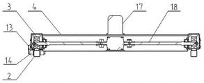
FIG. 1 is a schematic structural view of the cloth belt type gantry crane of the present invention;
FIG. 2 is a left side view of FIG. 1;
FIG. 3 is a view from A-A of FIG. 2;
fig. 4 is a schematic perspective view of the cloth belt type gantry crane of the present invention.
Detailed Description
The present invention will be described in further detail with reference to the accompanying drawings.
As shown in figure 1 and figure 4, the utility model discloses a strap formula longmen driving includes door type frame 1, and there is driving support 4 that the level was arranged in door type frame 1's periphery, and is fixed connection between door type frame 1 and driving support 4. The below on a set of corresponding limit of driving support 4 all has track 2, and driving support 4 all has walking wheel 3 with the lower part on track 2 corresponding limit, and has on driving support 4 to be used for the first actuating mechanism of walking wheel 3 pivoted of driven. A hanging bracket 15 is arranged in the door-shaped frame 1, a lifting hook 16 is arranged on the hanging bracket 15, and the two horizontal ends of the hanging bracket 15 are in vertical sliding fit with the vertical frames of the corresponding door-shaped frame 1. A lifting reel 8 is arranged on a cross beam of the door-shaped frame 1, and a cloth belt 6 is wound on the lifting reel 8. Lifting lugs 5 are arranged on the lifting frames 15, and the lower ends of the cloth belts 6 are sleeved on the lifting lugs 5 through folding lifting holes. And a second driving mechanism for driving the lifting reel 8 to rotate is arranged on the door-shaped frame 1. And guide side plates 9 are arranged at two axial ends of the lifting reel 8.
And a second rotating shaft 7 which is horizontally arranged is arranged on a cross beam of the door-shaped frame 1, and two ends of the second rotating shaft 7 are in running fit with the door-shaped frame 1. The second driving mechanism is a lifting speed reducer 10, and an output shaft of the lifting speed reducer 10 is in linkage fit with the second rotating shaft 7. The lifting reel 8 is sleeved on the second rotating shaft 7 and fixedly connected with the second rotating shaft. Promote speed reducer 10 and be located the middle part of 1 crossbeam of door type frame, all overlap on the second pivot 7 that promotes speed reducer 10 both sides correspondence and have promotion reel 8, all have lug 5 on the gallows 15 that corresponds under promoting reel 8, and promote on the reel 8 the winding strap 6 lower extreme all overlap on corresponding lug 5.
The number of the lifting pulleys 8 on the second rotating shafts 7 at the two sides of the lifting speed reducer 10 is not less than two, and the number of the lifting pulleys 8 on the second rotating shafts 7 at the two sides of the lifting speed reducer 10 is two. Lifting lugs 5 are arranged on the corresponding lifting frames 15 under each lifting reel 8, and the lower ends of the cloth belts 6 wound on each lifting reel 8 are sleeved on the corresponding lifting lugs 5.
As shown in fig. 2 and 3, the traveling crane support 4 is provided with a first rotating shaft 18 which is horizontally arranged, the first rotating shaft 18 is in rotating fit with the traveling crane support 4, two ends of the first rotating shaft 18 are respectively sleeved with a traveling wheel 3, and the two are fixedly connected. The first driving mechanism is a traveling speed reducer 17, and an output shaft of the traveling speed reducer 17 is in linkage fit with the first rotating shaft 18.
As shown in fig. 1 and 4, the traveling support 4 for one of the rails 2 has traveling guide seats 13 at both ends. The walking guide seat 13 is door-shaped, the inner sides of two vertical arms of the walking guide seat are provided with walking guide wheels 14, and the inner sides of the walking guide wheels 14 are abutted to the side surfaces of the corresponding tracks 2.
As shown in fig. 4, vertical guide rods 11 are arranged on the inner sides of the mullions of the portal frame 1, lifting guide wheels 12 are arranged at the ends of the hangers 15 corresponding to the two sides of the vertical guide rods 11, and the lifting guide wheels 12 are in rolling fit with the vertical guide rods 11, so that the two horizontal ends of the hangers 15 are in vertical sliding fit with the corresponding mullions of the portal frame 1.
The utility model discloses a strap formula longmen driving when using, utilizes the first pivot 18 of walking speed reducer 17 drive to rotate for the walking wheel 3 rolls on corresponding track 2, thereby drives driving support 4 and even whole driving realization horizontal migration. The lifting of the cloth belt type gantry crane hanger 15 is realized by a transmission mechanism which is matched with a second driving mechanism, a lifting reel 8, a cloth belt 6 and a lifting lug 5. Namely, the lifting speed reducer 10 drives the second rotating shaft 7 to rotate, the lifting reel 8 is driven to rotate, the cloth belt 6 wound on the lifting reel is wound and unwound, and the lifting lug 5 is pulled by the cloth belt 6 to drive the lifting frame 15 to lift. The direction curb plate 9 that promotes 8 axial both ends of hank wheel can be when receiving and releasing strap 6, and it is regular to lead to the winding of strap 6 on promoting hank wheel 8, avoids the strap 6 slippage. The second pivot 7 at promotion speed reducer 10 both sides respectively sets up the drive mechanism who is no less than two sets of promotion reel 8, strap 6 and lug 5, can reduce single strap 6's atress when guaranteeing 15 lift process stationarity of gallows, improves life. In addition, the phenomenon that after long-time use, one side of the hanger 15 drops due to the fracture of a certain cloth belt 6 can be prevented.
The utility model discloses a strap formula longmen driving adopts and promotes 5 matched with strap formula drive mechanism of lug on speed reducer 10, second pivot 7, promotion reel 8, strap 6 and the gallows 15, utilizes to promote reel 8 and receive and release the lift that strap 6 realized gallows 15, and the difficult production wearing and tearing can reduce the maintenance and the spare part change frequency of driving between strap 6 and lug 5, strap 6 and promotion reel 8, reduce use cost. Meanwhile, the stability of the cloth belt transmission is good, additional dynamic loads such as vibration and impact are not easy to generate during operation, driving energy can be saved, and potential safety hazards are eliminated. In addition, the cloth belt transmission hardly generates noise and does not pollute the environment.
Claims (8)
1. The cloth belt type gantry crane comprises a door-shaped frame (1), a crane support (4) horizontally arranged is arranged on the periphery of the door-shaped frame (1), and the door-shaped frame (1) is fixedly connected with the crane support (4); the track (2) is arranged below one group of corresponding edges of the travelling crane support (4), the travelling wheels (3) are arranged on the lower portions of the travelling crane support (4) and the corresponding edges of the track (2), and a first driving mechanism for driving the travelling wheels (3) to rotate is arranged on the travelling crane support (4); a hanging bracket (15) is arranged in the door-shaped frame (1), a lifting hook (16) is arranged on the hanging bracket (15), and the two horizontal ends of the hanging bracket (15) are in vertical sliding fit with the vertical frames of the corresponding door-shaped frame (1); the device is characterized in that a lifting reel (8) is arranged on a cross beam of the door-shaped frame (1), and a cloth belt (6) is wound on the lifting reel (8); the hanger (15) is provided with a lifting lug (5), and the lower end of the cloth belt (6) is sleeved on the lifting lug (5) through a folding lifting hole; and a second driving mechanism for driving the lifting reel (8) to rotate is arranged on the door-shaped frame (1).
2. A cloth-strip gantry crane according to claim 1, characterized in that the lifting sheaves (8) have guide side plates (9) at both axial ends.
3. The cloth-belt type gantry crane of claim 1, wherein a second rotating shaft (7) is horizontally arranged on a cross beam of the door-shaped frame (1), and two ends of the second rotating shaft (7) are in rotating fit with the door-shaped frame (1); the second driving mechanism is a lifting speed reducer (10), and an output shaft of the lifting speed reducer (10) is in linkage fit with the second rotating shaft (7); the lifting reel (8) is sleeved on the second rotating shaft (7) and fixedly connected with the second rotating shaft.
4. A cloth-belt type gantry crane according to claim 3, wherein the lifting reducer (10) is located in the middle of a cross beam of the portal frame (1), the second rotating shafts (7) corresponding to both sides of the lifting reducer (10) are respectively sleeved with a lifting reel (8), lifting lugs (5) are respectively arranged on the corresponding lifting frames (15) right below the lifting reels (8), and the lower ends of the cloth belts (6) wound on the lifting reels (8) are respectively sleeved on the corresponding lifting lugs (5).
5. A cloth belt type gantry crane according to claim 4, wherein the number of the lifting winch wheels (8) on the second rotating shafts (7) at both sides of the lifting reducer (10) is not less than two, lifting lugs (5) are arranged on the corresponding hanger (15) right below each lifting winch wheel (8), and the lower ends of the cloth belts (6) wound on each lifting winch wheel (8) are sleeved on the corresponding lifting lugs (5).
6. The cloth belt type gantry crane of claim 1, wherein the crane support (4) is provided with a first rotating shaft (18) which is horizontally arranged, the first rotating shaft (18) is in rotating fit with the crane support (4), two ends of the first rotating shaft (18) are sleeved with a traveling wheel (3), and the two are fixedly connected; the first driving mechanism is a walking speed reducer (17), and an output shaft of the walking speed reducer (17) is in linkage fit with the first rotating shaft (18).
7. A cloth belt type gantry crane according to any one of claims 1 to 6, wherein a travelling guide seat (13) is arranged at each end of a crane support (4) for one rail (2); the walking guide seat (13) is door-shaped, the inner sides of the two vertical arms are provided with walking guide wheels (14), and the inner sides of the walking guide wheels (14) are propped against the side surfaces of the corresponding tracks (2).
8. A cloth belt type gantry crane as claimed in any one of claims 1 to 6, wherein the inner sides of the vertical frames of the door-shaped frame (1) are provided with vertical guide rods (11), the ends of the corresponding hangers (15) at the two sides of the vertical guide rods (11) are provided with lifting guide wheels (12), and the lifting guide wheels (12) are in rolling fit with the vertical guide rods (11), so that the horizontal ends of the hangers (15) are in vertical sliding fit with the corresponding vertical frames of the door-shaped frame (1).
Priority Applications (1)
| Application Number | Priority Date | Filing Date | Title |
|---|---|---|---|
| CN201920905725.3U CN210214669U (en) | 2019-06-19 | 2019-06-19 | Cloth belt type gantry crane |
Applications Claiming Priority (1)
| Application Number | Priority Date | Filing Date | Title |
|---|---|---|---|
| CN201920905725.3U CN210214669U (en) | 2019-06-19 | 2019-06-19 | Cloth belt type gantry crane |
Publications (1)
| Publication Number | Publication Date |
|---|---|
| CN210214669U true CN210214669U (en) | 2020-03-31 |
Family
ID=69932191
Family Applications (1)
| Application Number | Title | Priority Date | Filing Date |
|---|---|---|---|
| CN201920905725.3U Active CN210214669U (en) | 2019-06-19 | 2019-06-19 | Cloth belt type gantry crane |
Country Status (1)
| Country | Link |
|---|---|
| CN (1) | CN210214669U (en) |
Cited By (2)
| Publication number | Priority date | Publication date | Assignee | Title |
|---|---|---|---|---|
| CN112520571A (en) * | 2020-11-30 | 2021-03-19 | 重庆聚飞金属科技有限公司 | Automatic accessory surface treatment production process |
| CN116463700A (en) * | 2022-01-12 | 2023-07-21 | 浙江日昇环保科技有限公司 | A lifting pulley device for electroplating line traveling |
-
2019
- 2019-06-19 CN CN201920905725.3U patent/CN210214669U/en active Active
Cited By (2)
| Publication number | Priority date | Publication date | Assignee | Title |
|---|---|---|---|---|
| CN112520571A (en) * | 2020-11-30 | 2021-03-19 | 重庆聚飞金属科技有限公司 | Automatic accessory surface treatment production process |
| CN116463700A (en) * | 2022-01-12 | 2023-07-21 | 浙江日昇环保科技有限公司 | A lifting pulley device for electroplating line traveling |
Similar Documents
| Publication | Publication Date | Title |
|---|---|---|
| CN214495437U (en) | Lifting mechanism of double-beam bridge crane | |
| CN208605004U (en) | A kind of stereo garage lifting device | |
| CN113336089B (en) | Swivel track transfer crane | |
| CN201834680U (en) | Low clearance flexibly connected crane car | |
| CN216785553U (en) | Eccentric load synchronous constant-speed conveying device for continuous casting slab lifting trolley | |
| CN112537723A (en) | Stage lifting machine | |
| CN215402697U (en) | Trackless rubber-tyred single-double speed electric hoist gantry crane | |
| CN110735549A (en) | lifting device for stereo garage | |
| CN203612789U (en) | Automatic cage curtain door free of brake for vertical shaft lifting cage | |
| CN116730186B (en) | A crane drive device | |
| CN215798047U (en) | Special crane for grinding roller | |
| CN216582508U (en) | Over-and-under type hangs transfer chain | |
| CN114132837B (en) | Anti-shaking lifting device for travelling crane | |
| CN217102854U (en) | Automatic rope arranging device for winch | |
| CN215402784U (en) | Electric hoist with semi-built-in noise reduction motor and speed reducer | |
| CN201648524U (en) | Bridge-type self-propelled trolley device for round steel strand pickling line | |
| CN213950365U (en) | Electric single-beam crane convenient to use | |
| CN217756566U (en) | Auxiliary replacing device for revolving arm of revolving platform of continuous casting machine | |
| CN207108264U (en) | A kind of electrodeless frequency control double-beam trolley of crane | |
| CN222524021U (en) | Single-beam crane trolley of electric hoist | |
| CN210340178U (en) | Low headroom three-in-one internal translational electric hoist | |
| CN221370349U (en) | Rope arrangement mechanism for lifting trolley | |
| CN209193387U (en) | Telescopic crane is driven in a kind of | |
| CN115610383A (en) | A steel wire drum lifting belt lateral telescopic power exchange equipment | |
| CN219296426U (en) | Walking mechanism |
Legal Events
| Date | Code | Title | Description |
|---|---|---|---|
| GR01 | Patent grant | ||
| GR01 | Patent grant |