Automatic foam cutting machine
Technical Field
The utility model relates to a cutting machine technical field especially relates to an automatic bubble membrane cutting machine.
Background
In prior art, the in-process that the cotton membrane of bubble was used need cut it, all is the manual work at present and tailors, generally adopts single tool to realize moreover, can't satisfy diversified cutting needs, has reduced production efficiency.
Disclosure of Invention
Not enough to above-mentioned prior art, the utility model provides a compound coating machine solves above-mentioned problem.
In order to solve the technical problem, the utility model discloses a following technical scheme:
an automatic foam cutting machine comprises a workbench horizontally arranged, wherein a groove is formed in the upper surface of the workbench, the groove is formed in the middle of the workbench, a first horizontal conveying mechanism and a second horizontal conveying mechanism which are consistent in conveying direction and are arranged on the same straight line with the horizontal plane are arranged in the groove, the feeding end of the second horizontal conveying mechanism is arranged at the discharging end of the first horizontal conveying mechanism, a gap is formed between the first horizontal conveying mechanism and the second horizontal conveying mechanism, the first horizontal conveying mechanism and the second horizontal conveying mechanism are in transmission connection with a first power input mechanism and a second power input mechanism respectively, a first positioning mechanism and a second positioning mechanism are arranged on two sides of the workbench respectively, the first positioning mechanism is arranged at the feeding end of the first horizontal conveying mechanism, the second positioning mechanism is arranged at the discharging end of the first horizontal conveying mechanism, the second positioning mechanism is fixedly connected with the supporting mechanism, and a downward cutting mechanism is arranged below the supporting mechanism.
Therefore, the automatic foam conveying can be realized by utilizing the first horizontal conveying mechanism and the second horizontal conveying mechanism.
Preferably, the first horizontal conveying mechanism comprises a first horizontal conveying belt, the rotating discs at two ends of the first horizontal conveying belt are provided with first rotating shafts, the first rotating shafts extend into the workbench and are in running fit with the workbench, and the rotating shaft at one end in transmission connection with the first power input mechanism extends out of the workbench; the horizontal transport mechanism of second includes the horizontal conveyer belt of second, the carousel at the horizontal conveyer belt both ends of second all is provided with the second pivot, the second pivot all extends to inside the workstation, with workstation normal running fit, wherein with the pivot of the transmission connection one end of second power input mechanism stretches out to outside the workstation.
Preferably, the first power input mechanism comprises a first driving motor, an output shaft of the first driving motor is vertically arranged upwards, a first helical gear is rotatably mounted on the output shaft of the first driving motor, and the first helical gear is in meshing transmission with a second helical gear mounted on the rotating shaft; the second power input mechanism comprises a second driving motor, an output shaft of the second driving motor is vertically arranged upwards, a third bevel gear is rotatably installed on the output shaft of the second driving motor, and the third bevel gear is in meshing transmission with a fourth bevel gear installed on the rotating shaft.
As optimization, the first positioning mechanism comprises a first air cylinder arranged horizontally and a first positioning block fixedly connected with the movable end of the first air cylinder; the second positioning mechanism comprises a second cylinder and a second positioning block, wherein the second cylinder is horizontally arranged, and the second positioning block is fixedly connected with the movable end of the second cylinder.
Therefore, the first cylinder, the first positioning block, the second cylinder and the second positioning block are used for positioning foam of different specifications conveniently.
As an optimization, the supporting mechanism is including setting up the crossbeam on the top of second locating piece, be equipped with the third cylinder of vertical direction on the crossbeam, the third cylinder can remove about the crossbeam, the expansion end of third cylinder is connected with the fixer, the center of fixer is equipped with the tool bit, the tool bit sets up first horizontal transport mechanism with directly over the gap between the horizontal transport mechanism of second, both sides are equipped with the layering around the tool bit, the layering is fixed through length adjustable chain on the third cylinder.
Therefore, the foam is guaranteed to be flat by the aid of the pressing strips and the chains, and the foam is conveniently cut by the cutter head.
Preferably, the bottom of the cross beam is provided with a moving groove, and the second positioning block is connected with the moving groove in a sliding mode.
Like this, through set up the shifting chute in the crossbeam bottom, the second locating piece of being convenient for removes, has improved the regulation efficiency of whole device.
And as optimization, one end of the cross beam is provided with a fourth cylinder in the horizontal direction, and the movable end of the fourth cylinder is fixedly connected with the fixed end of the third cylinder.
Like this, utilize the fourth cylinder to realize the removal of third cylinder, realize the cutting of tool bit to different positions.
Preferably, a winder is arranged at the top end of the chain and arranged on the third cylinder.
Therefore, the chain is adjusted by the winder, and the pressing strip can be automatically lifted and lowered conveniently.
Preferably, the range of the gap is 1-10 mm.
Therefore, when the cutter head moves left and right in the gap to cut foam, the first horizontal device and the second horizontal device cannot be scraped.
The utility model has the advantages that:
an automatic bubble cotton cutting machine, utilize first horizontal transport mechanism, the horizontal transport mechanism of second can realize the cotton automatic transport of bubble, recycle first positioning mechanism, second positioning mechanism and fix a position the bubble cotton, utilize layering and chain to guarantee the cotton level and smooth of bubble, the tool bit of being convenient for cuts the bubble cotton, improves cutting efficiency.
Drawings
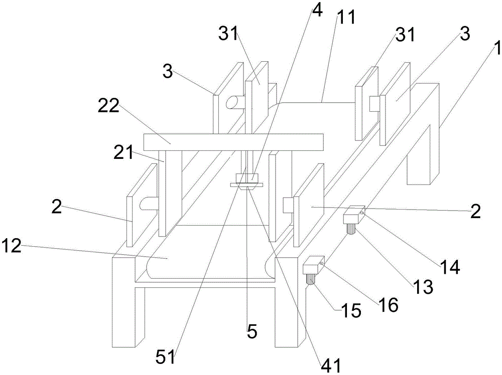
Fig. 1 is a schematic structural view of an automatic foam cutting machine according to the present invention.
Fig. 2 is a left side view of the automatic foam cutting machine of the present invention.
In the drawing, 1 is a workbench, 11 positions of a first horizontal conveyor belt, 12 is a second horizontal conveyor belt, 13 is a first driving motor, 14 is a first rotating shaft, 15 is a second driving motor, 16 is a second rotating shaft, 2 is a second air cylinder, 21 is a second positioning block, 22 is a cross beam, 3 is a first air cylinder, 31 is a first positioning block, 4 is a fixer, 41 is a cutter head, 5 is a pressing bar, 51 is a chain, 52 is a winder, 53 is a third air cylinder, 54 is a fourth air cylinder, and 6 is a moving groove.
Detailed Description
The present invention will be described in further detail with reference to the accompanying drawings.
As shown in the figure 1-2, an automatic foam cutting machine comprises a workbench 1 which is horizontally arranged, wherein a groove is arranged on the upper surface of the workbench 1, the groove is arranged in the middle of the workbench 1, a first horizontal transmission mechanism and a second horizontal transmission mechanism which have the same transmission direction and the same horizontal plane are arranged in the groove, the feeding end of the second horizontal transmission mechanism is arranged at the discharging end of the first horizontal transmission mechanism, a gap is arranged between the first horizontal transmission mechanism and the second horizontal transmission mechanism, the first horizontal transmission mechanism and the second horizontal transmission mechanism are respectively in transmission connection with a first power input mechanism and a second power input mechanism, a first positioning mechanism and a second positioning mechanism are respectively arranged at the two sides of the workbench 1, the first positioning mechanism is arranged at the feeding end of the first horizontal transmission mechanism, the second positioning mechanism is arranged at the discharging end of the first horizontal transmission mechanism, the second positioning mechanism is fixedly connected with the supporting mechanism, and a downward cutting mechanism is arranged below the supporting mechanism.
In this embodiment, the first horizontal conveying mechanism includes a first horizontal conveying belt 11, the rotating discs at two ends of the first horizontal conveying belt 11 are both provided with a first rotating shaft 14, the first rotating shafts 14 extend into the workbench 1 and are in running fit with the workbench 1, wherein the rotating shaft at one end in transmission connection with the first power input mechanism extends out of the workbench; the second horizontal transmission mechanism comprises a second horizontal transmission belt 12, the rotary tables at two ends of the second horizontal transmission belt 12 are provided with second rotary shafts 16, the second rotary shafts extend to the inside of the workbench 1 and are in running fit with the workbench 1, and the rotary shafts at one end of the second horizontal transmission mechanism in a transmission mode are extended out of the workbench.
In this embodiment, the first power input mechanism includes a first driving motor 13, an output shaft of the first driving motor 13 is disposed vertically upward, a first helical gear (not shown in the figure) is rotatably installed on the output shaft of the first driving motor 13, and the first helical gear is in meshing transmission with a second helical gear (not shown in the figure) installed on the rotating shaft; the second power input mechanism comprises a second driving motor 15, an output shaft of the second driving motor 15 is vertically arranged upwards, a third helical gear (not marked in the figure) is rotatably installed on the output shaft of the second driving motor, and the third helical gear is in meshing transmission with a fourth helical gear (not marked in the figure) installed on the rotating shaft.
In this embodiment, the first positioning mechanism includes a first cylinder 3 horizontally disposed and a first positioning block 31 fixedly connected with a movable end of the first cylinder; the second positioning mechanism comprises a second cylinder 2 horizontally arranged and a second positioning block 21 fixedly connected with the movable end of the second cylinder 2.
In this embodiment, the supporting mechanism includes the crossbeam 22 that sets up the 21 tops of second locating piece, be equipped with the third cylinder 53 of vertical direction on the crossbeam 22, the third cylinder 53 can move about along the crossbeam, the expansion end of third cylinder 53 is connected with fixer 4, the center of fixer 4 is equipped with tool bit 41, tool bit 41 sets up directly over the gap between first horizontal transport mechanism and the second horizontal transport mechanism, the front and back both sides of tool bit are equipped with layering 5, layering 5 is fixed on third cylinder 53 through length-adjustable chain 51.
In this embodiment, the bottom of the cross beam 22 is provided with a moving slot 6, and the second positioning block 21 is slidably connected with the moving slot 6.
In this embodiment, a horizontal fourth cylinder 54 is disposed at one end of the cross beam, and a movable end of the fourth cylinder 54 is fixedly connected to a fixed end of the third cylinder 53.
In this embodiment, a winder 52 is provided at the tip of the chain 51, and the winder is provided on a third cylinder 53.
In this embodiment, the gap is in the range of 1-10 mm.
The specific principle of the utility model is as follows: in the actual production process, foam to be cut is placed on a first horizontal conveying mechanism, rough positioning is carried out through a first positioning mechanism according to the specification of the foam to be cut, a first cylinder moves a first positioning block until the first positioning block touches the foam to be cut, the first horizontal conveying mechanism conveys the foam to be cut to a specified position, the first horizontal conveying mechanism stops operating, the second positioning mechanism carries out re-positioning, a second positioning block moves through a second positioning cylinder and a moving groove until a second positioning block is tightly attached to the foam to be cut, a fourth cylinder is started to control a third cylinder to be in a proper processing position, the length of a chain is adjusted according to the height of the foam to be cut to ensure that the bottommost end of a pressing bar just presses the foam, the third cylinder is started to control a fixer to move downwards, when the cutter head cuts the foam, the third cylinder controls the fixer to ascend after cutting, and lifting the pressing strip by using a winder and a chain, starting a second horizontal conveying mechanism to convey the cut foam to a material receiving end, and then cutting according to the steps.
The first cylinder, the second cylinder, the third cylinder, the fourth cylinder, the first driving motor and the second driving motor are all electrically connected with the controller, and the controller is used for controlling the movement of the cylinders and the motors. The controller may be a PLC controller.
The present invention relates to an automatic foam cutting machine, and may relate to a practical software, but the software used is the software most commonly used by those skilled in the art, and is not the scope of protection of the claims of the patent application.
Finally, it should be noted that: various modifications and alterations of this invention may be made by those skilled in the art without departing from the spirit and scope of this invention. Thus, to the extent that such modifications and variations of the present invention fall within the scope of the present claims and their equivalents, it is intended that the present invention encompass such modifications and variations as well.