CN210208824U - Efficient hydraulic heavy waste gantry shearing machine - Google Patents
Efficient hydraulic heavy waste gantry shearing machine Download PDFInfo
- Publication number
- CN210208824U CN210208824U CN201921194170.2U CN201921194170U CN210208824U CN 210208824 U CN210208824 U CN 210208824U CN 201921194170 U CN201921194170 U CN 201921194170U CN 210208824 U CN210208824 U CN 210208824U
- Authority
- CN
- China
- Prior art keywords
- board
- blade
- placing
- rod
- placing plate
- Prior art date
- Legal status (The legal status is an assumption and is not a legal conclusion. Google has not performed a legal analysis and makes no representation as to the accuracy of the status listed.)
- Active
Links
- 239000002699 waste material Substances 0.000 title claims description 12
- 238000010008 shearing Methods 0.000 title abstract description 28
- 230000007246 mechanism Effects 0.000 claims abstract description 18
- 230000009194 climbing Effects 0.000 claims abstract description 6
- 230000003139 buffering effect Effects 0.000 claims description 32
- 239000007787 solid Substances 0.000 claims description 6
- 238000003466 welding Methods 0.000 claims description 4
- 238000000034 method Methods 0.000 abstract description 5
- 230000008569 process Effects 0.000 abstract description 5
- 230000000694 effects Effects 0.000 description 4
- 210000003437 trachea Anatomy 0.000 description 3
- 230000001174 ascending effect Effects 0.000 description 2
- 230000008901 benefit Effects 0.000 description 2
- 238000010586 diagram Methods 0.000 description 2
- 239000000428 dust Substances 0.000 description 2
- 239000004744 fabric Substances 0.000 description 2
- 239000002184 metal Substances 0.000 description 2
- 238000003825 pressing Methods 0.000 description 2
- 230000002035 prolonged effect Effects 0.000 description 2
- 241000220317 Rosa Species 0.000 description 1
- 230000015572 biosynthetic process Effects 0.000 description 1
- 230000007547 defect Effects 0.000 description 1
- 238000012986 modification Methods 0.000 description 1
- 230000004048 modification Effects 0.000 description 1
Images



Landscapes
- Crushing And Pulverization Processes (AREA)
Abstract
The utility model discloses an efficient hydraulic pressure heavy useless longmen cutter, concretely relates to cutter technical field, including the mount, control switch is installed to the lateral wall of mount, and the top mid-mounting of mount has telescopic hydraulic cylinder, the inboard that telescopic hydraulic cylinder's bottom piston rod bottom is located the mount is connected with the knife rest, the blade is installed to the bottom of knife rest, the inboard below that is located the blade of mount is provided with places the board, place the bottom of board and install climbing mechanism, and the lateral wall of placing the board is connected with the intake pipe. The utility model discloses be convenient for cushion shearing process, avoid pushing down the speed and cause at the excessive speed and place and form the rigidity collision between board and the blade and cause the damage, prolong the blade and place the life of board, and can realize the function of automatic blanking, the convenient piece remaining after shearing on placing the board is cleared up simultaneously, and the piece after the clearance can carry out centralized processing.
Description
Technical Field
The utility model relates to a cutter technical field, more specifically say, the utility model relates to a heavy useless longmen cutter of efficient hydraulic pressure.
Background
The waste metal is required to be cut after being recycled, so that subsequent treatment is facilitated, and the cutting is required to use a shearing machine, wherein the shearing machine comprises a horizontal metal shearing machine and a gantry shearing machine, and the gantry shearing machine has the advantages of large shearing force and convenience in use.
Through retrieval, the Chinese utility model with publication number CN 208961100U discloses a gantry shearing machine, which comprises a mounting seat, wherein a U-shaped outer frame is fixedly arranged on the top side of the mounting seat, a telescopic hole is arranged on the inner wall of the bottom side of the U-shaped outer frame along the vertical direction, a telescopic rod is movably arranged in the telescopic hole, both ends of the telescopic rod extend out of the telescopic hole, a pushing plate is fixedly arranged at the bottom end of the telescopic rod, a fixed rod fixedly arranged on the inner wall of the bottom side of the U-shaped outer frame is arranged on one side of the telescopic rod, a pushing groove is arranged on one side of the pushing plate close to the fixed rod, a rotating hole is arranged on one side of the fixed rod along the horizontal direction, a rotating shaft is rotatably arranged in the rotating hole, when the hydraulic rod is stretched, the shearing knife can be driven to move up and down to carry out shearing operation, and the, not only the yield is improved.
But above-mentioned patent is too fast shearing process blade falling speed, is not convenient for cushion, easily causes to place and forms the rigidity collision between board and the blade and cause the damage, has shortened the blade and has placed the life of board, and does not have the function of automatic blanking, and inconvenient simultaneously is cleared up placing remaining piece after cuting on the board.
SUMMERY OF THE UTILITY MODEL
In order to overcome prior art's above-mentioned defect, the embodiment of the utility model provides an efficient hydraulic pressure heavily useless longmen cutter is convenient for cushion shearing process, avoid pushing down the speed and cause at the excessive speed and place and form the rigidity collision between board and the blade and cause the damage, the extension blade with place the life of board, and can realize the function of automatic blanking, the convenient remaining piece of back of cuting on placing the board is cleared up simultaneously, and the piece after the clearance can carry out centralized processing.
In order to achieve the above object, the utility model provides a following technical scheme: an efficient hydraulic heavy waste gantry shearing machine comprises a fixing frame, wherein a control switch is installed on the outer side wall of the fixing frame, a telescopic hydraulic cylinder is installed in the middle of the top end of the fixing frame, the bottom end of a bottom piston rod of the telescopic hydraulic cylinder is located on the inner side of the fixing frame and is connected with a knife rest, a blade is installed at the bottom of the knife rest, a placing plate is arranged on the inner side of the fixing frame and below the blade, a jacking mechanism is installed at the bottom of the placing plate, the outer side wall of the placing plate is connected with an air inlet pipe, one end of the air inlet pipe is located on the outer side of the fixing frame and is;
climbing mechanism is including connecting the buffer beam near placing four edges of board bottom, first spring has been cup jointed to the outside of buffer beam, and the bottom of buffer beam is connected with the fixing base, the inside wall of fixing base is connected with spacing slide bar, the middle part of spacing slide bar is provided with solid fixed ring, and the outside of spacing slide bar is located solid fixed ring's both sides position department and all is provided with two sliders, two sliders respectively with the fixing base and gu all install the second spring between the fixed ring, the bottom of placing the board is connected with the fixed block, the bottom symmetric connection of fixed block has first buffering branch and second buffering branch, the top at corresponding position department slider is all connected to the bottom of first buffering branch and second buffering branch.
In a preferred embodiment, a limiting block is arranged at the top end of the buffer rod and at the bottom of the placing plate, a fixing groove is arranged in the vertical direction inside the placing plate corresponding to the outside of the limiting block, and the cross section area of the opening at the bottom of the fixing groove is smaller than that of the limiting block.
In a preferred embodiment, the bottom end of the buffer rod is connected with the top of the fixed seat through a bolt, and the fixed seat is connected with the inner wall of the fixed frame through a bolt.
In a preferred embodiment, the connection mode between the limiting sliding rod and the fixed seat is welding, and the inner diameter of the vertical section of the sliding block is larger than the outer diameter of the vertical section of the limiting sliding rod.
In a preferred embodiment, the fixed block is connected with the bottom of the placing plate through a bolt, and the top ends of the first buffer supporting rod and the second buffer supporting rod are rotatably connected with the bottom of the fixed block through a first fixed shaft.
In a preferred embodiment, a second fixing shaft is connected between the top end of the sliding block and the bottom ends of the first buffer supporting rod and the second buffer supporting rod, and the first buffer supporting rod and the sliding block are rotatably connected through the second fixing shaft.
In a preferred embodiment, a knife groove is formed in the top of the placing plate corresponding to the position below the blade, the top of the placing plate is located behind the knife groove and is of an arc-shaped structure, a circular through hole is formed in the bottom of the knife groove, a pipe body interface is formed in the position, corresponding to the end portion of the air inlet pipe, of the outer wall of the placing plate, the air inlet pipe is communicated with the circular through hole, and a limiting hole is formed in the fixing frame in the vertical direction corresponding to the outer portion of the air inlet pipe.
In a preferred embodiment, the two outer side walls of the tool holder are provided with a fixture block, and a position of the inner side wall of the fixing frame corresponding to the outer position of the fixture block is provided with a limiting sliding groove in the vertical direction.
The utility model discloses a technological effect and advantage:
1. the utility model discloses a install climbing mechanism in the bottom of placing the board, climbing mechanism includes the buffer beam, first spring, the fixing base, the spacing slide bar, solid fixed ring, the slider, the second spring, the fixed block, first buffering branch, second buffering branch and the stopper, when using, when the bottom piston rod of telescopic pneumatic cylinder stretches out and makes the knife rest drive the blade to descend, the bottom of blade contacts the object to be sheared at first, in the process of pushing down, make placing the board descend and compress the first spring, and make the top of buffer beam retract the inside of placing the board and play the effect of preliminary buffering, then the fixed block pushes down, make the bottom of first buffering branch and second buffering branch all drive the slider to move to both sides, and then compress the second spring, play the cushioning effect when shearing again, avoid pushing down the too fast and causing and forming rigid collision between placing board and the blade and cause the damage, the service lives of the blade and the placing plate are prolonged, the jacking mechanism can push the placing plate to ascend when the blade ascends after shearing is completed, and the ascending pushing force enables an object placed on the arc-shaped surface of the placing plate to fall off after shearing, so that the function of automatic blanking is realized;
2. the utility model discloses a lateral wall placing the board is connected with the intake pipe, the outside that the one end of intake pipe is located the mount is connected at the air intake of air exhauster, the air outlet of air exhauster is connected with an album dirt sack through the trachea, after shearing the completion, remaining piece falls into the inside of circular through-hole from the sword groove, through starting the inside negative pressure that forms that the air exhauster made the intake pipe, and then make the inside piece of circular through-hole finally collect the inside to album dirt sack through the intake pipe, the convenient piece remaining after shearing on placing the board is cleared up, piece after the clearance can carry out centralized processing.
Drawings
Fig. 1 is a schematic structural diagram of the present invention.
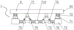
Fig. 2 is a schematic structural diagram of the middle jacking mechanism of the present invention.
Fig. 3 is a side sectional view of the middle placement plate of the present invention.
Fig. 4 is a sectional view of the junction between the middle buffer rod and the placing plate of the present invention.
Fig. 5 is a schematic view of a partial structure of the middle fixing frame of the present invention.
Fig. 6 is a schematic view of the structure of the joint between the middle tool holder and the fixing frame of the present invention.
The reference signs are: the automatic lifting device comprises a fixed frame 1, a control switch 2, a telescopic hydraulic cylinder 3, a knife rest 4, a blade 5, a placing plate 6, a jacking mechanism 7, an air inlet pipe 8, a suction fan 9, a dust collecting cloth bag 10, a clamping block 41, a limiting sliding groove 42, a knife groove 61, a circular through hole 62, a pipe body interface 63, a fixing groove 64, a limiting hole 81, a buffer rod 71, a first spring 72, a fixing seat 73, a limiting sliding rod 74, a sliding block 75, a second spring 76, a fixing block 77, a first buffer supporting rod 78, a second buffer supporting rod 79, a fixing ring 710 and a limiting block 711.
Detailed Description
The technical solutions in the embodiments of the present invention will be described clearly and completely with reference to the accompanying drawings in the embodiments of the present invention, and it is obvious that the described embodiments are only some embodiments of the present invention, not all embodiments. Based on the embodiments in the present invention, all other embodiments obtained by a person skilled in the art without creative work belong to the protection scope of the present invention.
The utility model provides an efficient hydraulic heavy waste gantry shearing machine, which comprises a fixed frame 1, wherein a control switch 2 is arranged on the outer side wall of the fixed frame 1, a telescopic hydraulic cylinder 3 is arranged in the middle of the top end of the fixed frame 1, the bottom end of a bottom piston rod of the telescopic hydraulic cylinder 3 is positioned at the inner side of the fixed frame 1 and is connected with a tool rest 4, two outer side walls of the tool rest 4 are both provided with a fixture block 41, a position of the inner side wall of the fixed frame 1, which corresponds to the outer position of the fixture block 41, is provided with a limit chute 42 in the vertical direction, a blade 5 is arranged at the bottom of the tool rest 4, a placing plate 6 is arranged at the inner side of the fixed frame 1, a jacking mechanism 7 is arranged at the bottom of the placing plate 6, the jacking mechanism 7 comprises buffer rods 71 which are connected at four corners near the bottom, the bottom end of the buffer rod 71 is connected with a fixed seat 73, the inner side wall of the fixed seat 73 is connected with a limit slide rod 74, the middle part of the limit slide rod 74 is provided with a fixed ring 710, the outer part of the limit slide rod 74 is provided with two sliders 75 at the positions of the two sides of the fixed ring 710, the two sliders 75 are respectively provided with a second spring 76 between the fixed seat 73 and the fixed ring 710, the bottom end of the placing plate 6 is connected with a fixed block 77, the bottom end of the fixed block 77 is symmetrically connected with a first buffer support rod 78 and a second buffer support rod 79, the bottom ends of the first buffer support rod 78 and the second buffer support rod 79 are respectively connected with the top of the slider 75 at the corresponding positions, the top end of the buffer rod 71 is provided with a limit block 711 at the bottom of the placing plate 6, the outer part of the placing plate 6 corresponding to the limit block is provided with a fixed groove 64 in the vertical, pass through bolted connection between the bottom of buffer pole 71 and the top of fixing base 73, pass through bolted connection between the inner wall of fixing base 73 and mount 1, connected mode between spacing slide bar 74 and the fixing base 73 is the welding, the perpendicular cross-section internal diameter of slider 75 is greater than the perpendicular cross-section external diameter of spacing slide bar 74, pass through bolted connection between fixed block 77 and the bottom of placing board 6, all rotate through first fixed axle between the top of first buffering branch 78 and second buffering branch 79 and the bottom of fixed block 77 and be connected, be connected with the second fixed axle between the top of slider 75 and the bottom of first buffering branch 78 and second buffering branch 79, rotate through the second fixed axle between first buffering branch 78 and second buffering branch 79 and the slider 75 and be connected.
As shown in fig. 1-4 and fig. 6, the specific implementation is as follows: when the lifting device is used, a piston rod at the bottom of the telescopic hydraulic cylinder 3 is controlled to extend out to push the knife rest 4 to descend, the fixture blocks 41 are arranged on the two outer side walls of the knife rest 4, the position, corresponding to the outer part of the fixture block 41, of the inner side wall of the fixing frame 1 is provided with the limiting sliding chute 42 in the vertical direction, so that the knife rest 4 is in sliding connection with the inner wall of the fixing frame 1 through the limiting sliding chute 42, the stability of the lifting of the knife rest 4 is improved, the knife blade 5 is installed at the bottom of the knife rest 4, the placing plate 6 is arranged below the knife blade 5 on the inner side of the fixing frame 1, the top of the placing plate 6 is positioned at the rear side of the knife groove 61 and is of an arc-shaped structure, the lifting mechanism 7 is installed at the bottom of the placing plate 6, the lifting mechanism 7 comprises buffer rods 71 connected at four corners, the inner side wall of the fixed seat 73 is connected with a limiting slide rod 74, a fixed ring 710 is arranged in the middle of the limiting slide rod 74, two sliders 75 are arranged at positions, located at two sides of the fixed ring 710, on the outer portion of the limiting slide rod 74, second springs 76 are respectively arranged between the two sliders 75 and the fixed ring 73 and the fixed ring 710, the bottom end of the placing plate 6 is connected with a fixed block 77, the bottom end of the fixed block 77 is symmetrically connected with a first buffering support rod 78 and a second buffering support rod 79, the bottom ends of the first buffering support rod 78 and the second buffering support rod 79 are respectively connected with the top of the slider 75 at the corresponding positions, a limiting block 711 is arranged at the bottom end of the placing plate 6, a fixing groove 64 is arranged in the vertical direction of the inner portion of the placing plate 6 corresponding to the outer portion of the limiting block 711, the cross sectional area of an opening at the bottom of the fixing groove 64, the fixed seat 73 is connected with the inner wall of the fixed frame 1 through a bolt, the limit slide rod 74 is connected with the fixed seat 73 through welding, the inner diameter of the vertical section of the sliding block 75 is larger than the outer diameter of the vertical section of the limit slide rod 74, the fixed block 77 is connected with the bottom of the placing plate 6 through a bolt, the top ends of the first buffer supporting rod 78 and the second buffer supporting rod 79 are rotatably connected with the bottom of the fixed block 77 through a first fixed shaft, the top end of the sliding block 75 is connected with the bottom ends of the first buffer supporting rod 78 and the second buffer supporting rod 79 through a second fixed shaft, the first buffer supporting rod 78 and the second buffer supporting rod 79 are rotatably connected with the sliding block 75 through a second fixed shaft, when in use, when a piston rod at the bottom of the telescopic hydraulic cylinder 3 extends out to enable the knife rest 4 to drive the knife blade 5 to descend, the bottom of the knife 5 firstly contacts with an object to be cut, and make the top of buffer beam 71 take in and place the inside of board 6 and play preliminary buffering effect, then fixed block 77 pushes down, make the bottom of first buffering branch 78 and second buffering branch 79 all drive slider 75 and move to both sides, and then compress second spring 76, play the cushioning effect when cuting once more, avoid pushing down the speed too fast and cause and place and form rigid collision between board 6 and the blade 5 and cause the damage, prolong the life of blade 5 and place board 6, and after the shearing is accomplished, when blade 5 rose, climbing mechanism 7 can promote to place board 6 and rise, the impetus that rises makes and puts the object on placing board 6 arcwall face after cutting and drops, realize the function of automatic blanking.
The lateral wall of placing board 6 is connected with intake pipe 8, the air intake at air exhauster 9 is connected in the outside that intake pipe 8's one end is located mount 1, the air outlet of air exhauster 9 is connected with collection dirt sack 10 through the trachea, the below position department that the top of placing board 6 corresponds blade 5 is provided with sword groove 61, and the top of placing board 6 is located the rear side in sword groove 61 and is the arc structure, the bottom in sword groove 61 is provided with circular through-hole 62, the tip position department that the outer wall of placing board 6 corresponds intake pipe 8 is provided with body interface 63, communicate between intake pipe 8 and the circular through-hole 62, the inside of mount 1 corresponds the outside of intake pipe 8 and is provided with spacing hole 81 in the vertical direction.
As shown in fig. 1, 3 and 5, the specific implementation is as follows: the outer side wall of the placing plate 6 is connected with an air inlet pipe 8, one end of the air inlet pipe 8 is positioned at the outer side of the fixing frame 1 and is connected with an air inlet of an exhaust fan 9, an air outlet of the exhaust fan 9 is connected with a dust collecting cloth bag 10 through an air pipe, the top of the placing plate 6 is provided with a knife groove 61 at a position corresponding to the lower part of the blade 5, the width of the knife groove 61 is larger than the thickness of the bottom of the blade 5 and smaller than the thickness of the top of the blade 5, the bottom of the knife groove 61 is provided with a circular through hole 62, the outer wall of the placing plate 6 is provided with a pipe body interface 63 at a position corresponding to the end part of the air inlet pipe 8, the air inlet pipe 8 is communicated with the circular through hole 62, the inside of the fixing frame 1 is provided with a limiting hole 81 in, and then make the inside piece of circular through-hole 62 finally collect the inside to collection dirt sack 10 through intake pipe 8, conveniently clear up placing remaining piece after the board 6 goes up the shearing, and the piece after the clearance can carry out centralized processing.
The utility model discloses the theory of operation:
referring to the attached drawings 1-4 and fig. 6 of the specification, the top of the placing plate 6 is arranged at the rear side of the knife slot 61 and is of an arc structure, and the jacking mechanism 7 is arranged at the bottom of the placing plate 6, the jacking mechanism 7 comprises a buffer rod 71, a first spring 72, a fixed seat 73, a limiting slide rod 74, a fixed ring 710, a sliding block 75, a second spring 76, a fixed block 77, a first buffer support rod 78, a second buffer support rod 79 and a limiting block 711, when in use, when a bottom piston rod of the telescopic hydraulic cylinder 3 extends out to enable the knife rest 4 to drive the knife blade 5 to descend, the bottom of the knife blade 5 first contacts with an object to be cut, in the process of pressing down, the placing plate 6 is enabled to descend to compress the first spring 72, the top of the buffer rod 71 is enabled to be retracted into the placing plate 6 to play a role of primary buffering, then the fixed block 77 is pressed down, the bottom ends of the first buffer support rod 78 and the, the second spring 76 is further compressed, the buffering effect during shearing is achieved again, the situation that rigid collision is formed between the placing plate 6 and the blade 5 due to the fact that the pressing speed is too high to damage the placing plate 6 and the blade 5 is avoided, the service lives of the blade 5 and the placing plate 6 are prolonged, the jacking mechanism 7 can push the placing plate 6 to ascend when the blade 5 ascends after shearing is completed, the ascending pushing force enables objects placed on the arc-shaped surface of the placing plate 6 to fall off after shearing, and the automatic blanking function is achieved;
further, refer to description figure 1, figure 3 and figure 5, lateral wall through placing board 6 is connected with intake pipe 8, the air intake at air exhauster 9 is connected in the outside that the one end of intake pipe 8 is located mount 1, the air outlet of air exhauster 9 is connected with album dirt sack 10 through the trachea, after the shearing is accomplished, remaining piece falls into the inside of circular through-hole 62 from sword groove 61, make the inside formation negative pressure of intake pipe 8 through starting air exhauster 9, and then make the inside piece of circular through-hole 62 finally collect the inside to album dirt sack 10 through intake pipe 8, conveniently clear up placing board 6 and cut remaining piece after the back, piece after the clearance can carry out centralized processing.
And finally: the above description is only for the preferred embodiment of the present invention and should not be taken as limiting the invention, and any modifications, equivalent replacements, improvements, etc. made within the spirit and principle of the present invention should be included in the protection scope of the present invention.
Claims (8)
1. The utility model provides a heavy useless longmen cutter of efficient hydraulic pressure, includes mount (1), its characterized in that: the outer side wall of the fixing frame (1) is provided with a control switch (2), the middle part of the top end of the fixing frame (1) is provided with a telescopic hydraulic cylinder (3), the bottom end of a piston rod at the bottom of the telescopic hydraulic cylinder (3) is positioned at the inner side of the fixing frame (1) and is connected with a knife rest (4), the bottom of the knife rest (4) is provided with a blade (5), the inner side of the fixing frame (1) is positioned below the blade (5) and is provided with a placing plate (6), the bottom of the placing plate (6) is provided with a jacking mechanism (7), the outer side wall of the placing plate (6) is connected with an air inlet pipe (8), one end of the air inlet pipe (8) is positioned at the outer side of the fixing frame (1) and is connected with an air inlet;
climbing mechanism (7) including connecting buffer rod (71) being close to and placing four edges of board (6) bottom, first spring (72) have been cup jointed to the outside of buffer rod (71), and the bottom of buffer rod (71) is connected with fixing base (73), the inside wall of fixing base (73) is connected with spacing slide bar (74), the middle part of spacing slide bar (74) is provided with solid fixed ring (710), and the outside of spacing slide bar (74) is located both sides position department of solid fixed ring (710) and all is provided with two slider (75), two slider (75) respectively with fixing base (73) and solid fixed ring (710) between all install second spring (76), the bottom of placing board (6) is connected with fixed block (77), the bottom symmetric connection of fixed block (77) has first buffering branch (78) and second buffering branch (79), the bottom of first buffering branch (78) and second buffering branch (79) all is connected in corresponding position department A top of the slider (75).
2. The high efficiency hydraulic heavy waste gantry shear of claim 1, wherein: the top end of the buffer rod (71) is located at the bottom of the placing plate (6) and is provided with a limiting block (711), a fixing groove (64) is formed in the vertical direction in the inside of the placing plate (6) corresponding to the outside of the limiting block (711), and the cross section area of the opening at the bottom of the fixing groove (64) is smaller than that of the limiting block (711).
3. The high efficiency hydraulic heavy waste gantry shear of claim 1, wherein: the bottom end of the buffer rod (71) is connected with the top of the fixed seat (73) through a bolt, and the fixed seat (73) is connected with the inner wall of the fixed frame (1) through a bolt.
4. The high efficiency hydraulic heavy waste gantry shear of claim 1, wherein: the connecting mode between the limiting sliding rod (74) and the fixed seat (73) is welding, and the inner diameter of the vertical section of the sliding block (75) is larger than the outer diameter of the vertical section of the limiting sliding rod (74).
5. The high efficiency hydraulic heavy waste gantry shear of claim 1, wherein: the fixing block (77) is connected with the bottom of the placing plate (6) through a bolt, and the top ends of the first buffer supporting rod (78) and the second buffer supporting rod (79) are rotatably connected with the bottom of the fixing block (77) through a first fixing shaft.
6. The high efficiency hydraulic heavy waste gantry shear of claim 1, wherein: the top of slider (75) and the bottom of first buffering branch (78) and second buffering branch (79) are connected with the second fixed axle between, rotate through the second fixed axle between first buffering branch (78) and second buffering branch (79) and slider (75) and be connected.
7. The high efficiency hydraulic heavy waste gantry shear of claim 1, wherein: the utility model discloses a cutting tool, including placing board (6), place the below position department that the top of board (6) corresponds blade (5) and be provided with sword groove (61), and the top of placing board (6) is located the rear side in sword groove (61) and is the arc structure, the bottom in sword groove (61) is provided with circular through-hole (62), the tip position department that the outer wall of placing board (6) corresponds intake pipe (8) is provided with body interface (63), communicate between intake pipe (8) and circular through-hole (62), the inside of mount (1) corresponds the outside of intake pipe (8) and is provided with spacing hole (81) on the vertical direction.
8. The high efficiency hydraulic heavy waste gantry shear of claim 1, wherein: the two outer side walls of the tool rest (4) are both provided with a clamping block (41), and the outer position of the inner side wall of the fixing frame (1) corresponding to the clamping block (41) is provided with a limiting sliding groove (42) in the vertical direction.
Priority Applications (1)
| Application Number | Priority Date | Filing Date | Title |
|---|---|---|---|
| CN201921194170.2U CN210208824U (en) | 2019-07-27 | 2019-07-27 | Efficient hydraulic heavy waste gantry shearing machine |
Applications Claiming Priority (1)
| Application Number | Priority Date | Filing Date | Title |
|---|---|---|---|
| CN201921194170.2U CN210208824U (en) | 2019-07-27 | 2019-07-27 | Efficient hydraulic heavy waste gantry shearing machine |
Publications (1)
| Publication Number | Publication Date |
|---|---|
| CN210208824U true CN210208824U (en) | 2020-03-31 |
Family
ID=69918559
Family Applications (1)
| Application Number | Title | Priority Date | Filing Date |
|---|---|---|---|
| CN201921194170.2U Active CN210208824U (en) | 2019-07-27 | 2019-07-27 | Efficient hydraulic heavy waste gantry shearing machine |
Country Status (1)
| Country | Link |
|---|---|
| CN (1) | CN210208824U (en) |
Cited By (1)
| Publication number | Priority date | Publication date | Assignee | Title |
|---|---|---|---|---|
| CN120551470A (en) * | 2025-07-31 | 2025-08-29 | 华翔(洪洞)智能科技有限公司 | A casting shearing and separation device |
-
2019
- 2019-07-27 CN CN201921194170.2U patent/CN210208824U/en active Active
Cited By (1)
| Publication number | Priority date | Publication date | Assignee | Title |
|---|---|---|---|---|
| CN120551470A (en) * | 2025-07-31 | 2025-08-29 | 华翔(洪洞)智能科技有限公司 | A casting shearing and separation device |
Similar Documents
| Publication | Publication Date | Title |
|---|---|---|
| CN215393240U (en) | Laser cutting machine is used in sheet metal component processing with waste recovery structure | |
| CN112123002A (en) | Energy-concerving and environment-protective sweeps recovery unit for machine tool machining | |
| CN211993113U (en) | Automatic paper cutter | |
| CN219054564U (en) | Die cutting machine with automatic material removing structure | |
| CN214867581U (en) | Dust removal filter bag skeleton apparatus for producing | |
| CN213531051U (en) | Continuous feed type cutting device | |
| CN217414295U (en) | Section bar cutting device with dustproof construction | |
| CN215881847U (en) | Formaldehyde adsorption paper cutting device | |
| CN212948169U (en) | A new type of stable punching machine | |
| CN112775261A (en) | Steel plate punching machine tool | |
| CN210308213U (en) | Panel processing trimming machine that possesses dust removal function | |
| CN217551902U (en) | Adjustable automatic deviation rectifying steel plate cutting machine | |
| CN222552302U (en) | A cutting device for piston rod production | |
| CN219130923U (en) | Cutting device for machine-building | |
| CN219402572U (en) | Automatic chip-removing plate cutting device | |
| CN218874712U (en) | Floor type boring and milling machine with scrap collecting function | |
| CN220427483U (en) | Combined cutter for shearing silicon steel sheet of transformer | |
| CN206123789U (en) | Scrap pick-up mechanism for multifunctional automatic cutting machine | |
| CN219507821U (en) | Glass cutting and slicing table | |
| CN217802564U (en) | Decorate ceramic tile cutting machine for engineering with dust removal structure | |
| CN219465090U (en) | Aluminum alloy cutting platform | |
| CN222985573U (en) | Waste collection device and wire bending machine | |
| CN218700232U (en) | Firm convenient die-cut frock is used in glass processing | |
| CN217344660U (en) | Wind power suction structure of mechanical cutting device | |
| CN221774061U (en) | A curtain wall aluminum plate engraving machine with automatic aluminum chip removal |
Legal Events
| Date | Code | Title | Description |
|---|---|---|---|
| GR01 | Patent grant | ||
| GR01 | Patent grant | ||
| PE01 | Entry into force of the registration of the contract for pledge of patent right |
Denomination of utility model: An Efficient Hydraulic Heavy Waste Gantry Shearing Machine Effective date of registration: 20230615 Granted publication date: 20200331 Pledgee: China Postal Savings Bank Co.,Ltd. Xintai City sub branch Pledgor: Shandong Jiangshan Heavy Industry Machinery Co.,Ltd. Registration number: Y2023980043954 |
|
| PE01 | Entry into force of the registration of the contract for pledge of patent right |