CN210207189U - Powder filtering screen and vertical mill powder selecting device - Google Patents
Powder filtering screen and vertical mill powder selecting device Download PDFInfo
- Publication number
- CN210207189U CN210207189U CN201920640381.8U CN201920640381U CN210207189U CN 210207189 U CN210207189 U CN 210207189U CN 201920640381 U CN201920640381 U CN 201920640381U CN 210207189 U CN210207189 U CN 210207189U
- Authority
- CN
- China
- Prior art keywords
- powder
- filter
- plate
- vertical mill
- filtering sieve
- Prior art date
- Legal status (The legal status is an assumption and is not a legal conclusion. Google has not performed a legal analysis and makes no representation as to the accuracy of the status listed.)
- Expired - Fee Related
Links
- 239000000843 powder Substances 0.000 title claims abstract description 150
- 238000001914 filtration Methods 0.000 title claims abstract description 40
- 239000000463 material Substances 0.000 claims description 35
- 239000007787 solid Substances 0.000 claims description 8
- 239000000428 dust Substances 0.000 claims description 4
- 230000008878 coupling Effects 0.000 claims 1
- 238000010168 coupling process Methods 0.000 claims 1
- 238000005859 coupling reaction Methods 0.000 claims 1
- 239000002245 particle Substances 0.000 abstract description 8
- 230000005484 gravity Effects 0.000 abstract description 3
- 238000012216 screening Methods 0.000 abstract 2
- 238000007599 discharging Methods 0.000 description 5
- 238000000034 method Methods 0.000 description 4
- 230000015572 biosynthetic process Effects 0.000 description 3
- 238000005755 formation reaction Methods 0.000 description 3
- 230000000630 rising effect Effects 0.000 description 2
- 238000000926 separation method Methods 0.000 description 2
- 238000003491 array Methods 0.000 description 1
- 230000001174 ascending effect Effects 0.000 description 1
- 230000009286 beneficial effect Effects 0.000 description 1
- 239000003638 chemical reducing agent Substances 0.000 description 1
- 238000010586 diagram Methods 0.000 description 1
- 238000009434 installation Methods 0.000 description 1
- 238000012986 modification Methods 0.000 description 1
- 230000004048 modification Effects 0.000 description 1
- 239000002994 raw material Substances 0.000 description 1
- 238000005096 rolling process Methods 0.000 description 1
- 239000002893 slag Substances 0.000 description 1
- 230000003068 static effect Effects 0.000 description 1
Images




Landscapes
- Crushing And Grinding (AREA)
Abstract
The utility model relates to a vertical mill accessory field, concretely relates to powder filtering sieve and vertical mill powder selecting device, the utility model discloses a vertical mill powder selecting device comprises a powder filtering sieve, a powder selecting rotor, a driving motor and a shell, the powder filtering sieve is a circular cylinder formed by powder filtering sieve plates, the powder filtering sieve plate is a long strip-shaped plate body, the cross section of the powder filtering sieve plate is 'C' -shaped, the inner edge of the powder filtering sieve plate is tangent to the inner circle of the circular cylinder of the powder filtering sieve plate, the air flow entering the powder selecting device is guided, the air flow flows along the inner edge of the powder filtering sieve plate, the powder and the particles mixed in the air flow also flow along with the air flow, because the large particle specific gravity is slow along with the air flow, the powder filtering sieve plate can drop because of being impacted, only small particles or micro powder can continue to enter the powder selecting rotor along with the air flow rotation, and then are collected, the utility model discloses twice screening is carried out on the powder at the powder filtering sieve, and (4) thinning the powder screening to ensure that the collected powder is uniform and consistent.
Description
Technical Field
The utility model relates to a found mill accessory field, concretely relates to filter sieve and found mill selection powder device.
Background
The vertical mill grinding process is completed by a set of grinding devices (i.e. grinding roller and grinding disc), and the materials are ground into powder between the grinding roller and the grinding disc. The grinding device is driven by the grinding disc to rotate and drive the grinding rollers correspondingly, and the grinding pressure is mainly used for pressurizing the grinding disc materials by a set of hydraulic device except the self weight of the grinding rollers. The material after grinding has a lot of coarse powder, and the powder is selected by a matched powder selecting machine, the powder selecting process of the powder is that the air flow is selected, most coarse powder automatically falls on a grinding disc in the air flow flowing process, and is received for grinding again, and the rest coarse powder is selected by the powder selecting machine to be a finished product, and is sent to a finished product storage room by a dust collecting and conveying system.
The motor drives the millstone to rotate through the vertical speed reducer, and the solid raw material enters the center of the millstone from the feed inlet through the air locking feeding device, is thrown to the periphery of the millstone under the action of a centrifugal force field and is crushed by repeated grinding of the grinding roller. The crushed material overflows from the edge of the grinding disc, the powdery material in the crushed material is carried by high-speed airflow rising from the lower part of the machine, when the rising airflow and the powdery material pass through the powder separator on the upper part of the mill, under the action of a rotor rotating rapidly, coarse powder is separated out and falls into the center of the grinding disc for grinding again, fine powder is discharged from the upper part of the mill along with the airflow and is collected in a dust collection device, and the product is obtained.
The powder separation device of the vertical mill is a device for separating coarse powder and micro powder from ascending air flow, and a general powder separation device is arranged at the top of the vertical mill, and adopts a mode of combining a moving blade and a static blade.
Disclosure of Invention
For solving the too big problem of vertical mill selection powder particle size distribution, the utility model provides a filter sieve and vertical mill selection powder device, the particle size selection of its purpose accurate selection powder device reduces the particle size distribution in the finished product.
In order to realize the purpose, the technical scheme of the utility model is that: a powder filtering screen of a vertical mill comprises a material collecting barrel, a discharging pipe and a filtering plate, wherein the material collecting barrel is a circular truncated cone-shaped barrel with a large upper section and a small lower section, the discharging pipe is arranged at the lower end of the material collecting barrel, and the discharging pipe is a cylindrical barrel; the top surface of the material collecting barrel is connected with a filter plate, the filter plate is an annular plate body, the inner edge of the filter plate is welded and fixed with the material collecting barrel, a plurality of through holes which are communicated up and down are arranged in an annular array on the filter plate, and the through holes are rectangular; the powder sieve is strained to filter upper portion being provided with, strain the powder sieve and be rectangular shape plate body, strain the cross-section of powder sieve and be "C" font, a plurality of powder sieves of straining are annular array on the filter inner edge, strain powder sieve lower extreme and filter fixed connection, the solid fixed ring of top fixedly connected with, solid fixed ring be the annular plate body.
The width of the through hole on the filter plate is smaller than the maximum distance between two adjacent filter powder sieve plates.
The outer surface of the powder filtering sieve plate is tangent to the inner side surface of a circular ring formed by the powder filtering sieve plates.
The material collecting barrel, the discharging pipe and the filter plate are coaxial.
A powder selecting device of a vertical mill comprises a powder filtering screen, a powder selecting rotor, a rotating shaft, a driving motor and a shell, wherein a filter plate of the powder filtering screen is fixedly connected with the shell of the vertical mill, the powder selecting rotor is arranged in the powder filtering screen, vertical plates and a bottom plate of the powder selecting rotor are cylindrical, the vertical plates are annularly arrayed to form a cylinder, the bottom plate is fixedly arranged below the cylinder formed by the vertical plates, an included angle α is formed between the vertical plates on the powder selecting rotor and the radius of the powder selecting rotor, the vertical plates are fixed on the rotating shaft through a support ring, the support ring is annular, a support rod is arranged in the support ring and fixedly connected with the rotating shaft, the rotating shaft penetrates through the shell of the vertical mill and extends out of the shell of the vertical mill, and the top of the rotating shaft is connected with the driving motor.
The included angle α is 75-85 degrees.
The powder selecting rotor, the rotating shaft and the powder filtering sieve are coaxial.
The bottom plate is in a circular truncated cone shape and is fixedly connected with the rotating shaft, a discharge hole is formed in the upper end of the shell of the vertical mill, and the upper portion of the powder selecting rotor is communicated with the discharge hole.
Through the technical scheme, the beneficial effects of the utility model are that:
the utility model discloses a cross-section of straining powder sieve board is "C" font, and the surface of straining the powder sieve is tangent with a plurality of powder sieve board group formations ring medial surfaces of straining, the powder that grinds out can be strained the powder sieve board direction along with the air current when straining the powder sieve, along straining powder sieve plate surface removal, because the surface of straining the powder sieve is tangent with a plurality of powder sieve board group formations ring medial surfaces of straining, and the middlings is than great than the weight, turn to the ability along with the air current and be less than the miropowder, consequently when miropowder turns to along with the air current, the middlings can be beaten on the ring medial surface of straining the powder sieve formation because of inertia, and then drop inside the feed cylinder that gathers materials, return by the feed cylinder and continue.
The utility model discloses a through-hole width on the filter is less than the maximum spacing of adjacent two powder sieve strainers of straining, has guaranteed that the material through the filter is not more than two maximum spacings of straining the powder sieve on the granularity, consequently does not have the bold material that splashes because the grinding roll rolls and gets into the selection powder device, causes the damage of device.
Drawings
FIG. 1 is a schematic view of the powder filtering screen of the present invention;
FIG. 2 is a front view of the powder filter of the present invention;
FIG. 3 is a cross-sectional view A-A of FIG. 2;
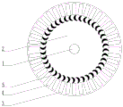
FIG. 4 is an installation diagram of a powder selecting device of a vertical mill of the present invention;
FIG. 5 is a schematic view of the powder selecting rotor of the present invention;
fig. 6 is a sectional view B-B of fig. 5.
The reference numbers in the drawings are as follows: 1 is the unloading pipe, 2 is the feed collecting barrel, 3 is the filter, 4 is the through-hole, 5 is for straining the powder sieve, 6 is solid fixed ring, 7 is for straining the powder sieve, 8 is the casing, 9 is the selection powder rotor, 10 is the discharge gate, 11 is the rotation axis, 12 is driving motor, 13 is the bottom surface, 14 is the riser, 15 is the support ring, 16 is the connecting rod.
Detailed Description
The invention will be further explained with reference to the drawings and the detailed description below:
as shown in fig. 1 to 6, the powder filtering screen of the vertical mill comprises a material collecting barrel 2, a blanking pipe 1 and a filtering plate 3, wherein the material collecting barrel 2 is an inverted circular truncated cone-shaped barrel with a large upper section and a small lower section, the blanking pipe 1 is arranged at the lower end of the material collecting barrel 2, the blanking pipe 1 is a cylindrical barrel, and the upper end of the blanking pipe 1 is welded and fixed with the lower end of the material collecting barrel 2; the top surface of the material collecting barrel 2 is connected with a filter plate 3, the filter plate 3 is a circular plate body, the inner edge of the filter plate 3 is welded and fixed with the material collecting barrel 2, a plurality of through holes 4 which are communicated up and down are arranged on the filter plate 3 in a circular array, the through holes 4 are rectangular, and the material collecting barrel 2, the blanking pipe 1 and the filter plate 3 are coaxial; 3 upper portions of filter are provided with and strain powder sieve 5, strain powder sieve 5 for rectangular shape plate body, strain powder sieve 5's cross-section and be "C" font, a plurality of powder sieves 5 of straining are annular array on 3 inner edges of filter, strain 5 lower extremes of powder sieve and 3 fixed connection of filter, the solid fixed ring of top fixedly connected with 6, solid fixed ring 6 be the annular plate body.
The width of the through holes 4 on the filter plate 3 is smaller than the maximum distance between two adjacent filter powder sieve plates 5, so that the material passing through the filter plate is not more than the maximum distance between two filter powder sieve plates in particle size, and therefore, the large material splashed due to rolling of the grinding roller does not enter the powder selecting device, and the device is not damaged.
The surface of straining powder sieve board 5 tangent with the medial surface of the ring that a plurality of powder sieve boards 5 of straining are constituteed, the powder of grinding out can be strained powder sieve board 5 direction when straining powder sieve board 5 along the air current process, along straining 5 surface movements of powder sieve board, because the surface of straining powder sieve board 5 is tangent with a plurality of 5 group shape of straining powder sieve boards ring medial surfaces that take shape, and the middlings specific gravity is big, turn to the ability along with the air current and be weak in the miropowder, consequently when the miropowder turns to along with the air current, the middlings can be beaten on straining the ring medial surface that powder sieve board 5 formed because of inertia, and then drop inside collection feed cylinder 2, return by feed cylinder 1 and continue to be ground.
A powder selecting device of a vertical mill comprises a powder filtering screen, a powder selecting rotor 9, a rotating shaft 11, a driving motor 12 and a shell 8, wherein a filter plate 3 of the powder filtering screen is fixedly connected with the shell 8 of the vertical mill, the powder selecting rotor 9 is arranged in the powder filtering screen, vertical plates 14 and a bottom plate 13 of the powder selecting rotor 9 are cylindrical and are formed by a plurality of annular arrays of the vertical plates 14, the bottom plate 13 is fixedly arranged below the cylinder formed by the vertical plates 14, an included angle α is formed between the vertical plates 14 on the powder selecting rotor 9 and the radius of the powder selecting rotor 9, the vertical plates 14 are fixed on the rotating shaft 11 through a support ring 15, the support ring 15 is annular, a support rod is arranged in the support ring 15 and is fixedly connected with the rotating shaft 11, the rotating shaft 11 penetrates through and extends out of the shell 8 of the vertical mill, and the top of the rotating shaft 11 is connected with.
The included angle α is 75-85 degrees.
The powder selecting rotor 9 and the rotating shaft 11 are coaxial with the powder filtering screen.
The bottom plate 13 is in a circular truncated cone shape, the bottom plate 13 is fixedly connected with the rotating shaft 11, the upper end of the vertical mill shell 8 is provided with a discharge hole 10, and the upper part of the powder selecting rotor 9 is communicated with the discharge hole 10.
The drive motor 12 is a large YTM series high voltage three-phase asynchronous motor manufactured by shengyangcheng motors ltd.
In the work, the materials ground by the grinding roller of the vertical mill are blown by strong wind to be upward from the through holes of the filter plate 3, wherein large-particle slag is blocked by the through hole 4 and falls back to the grinding platform again for continuous grinding, the powdery material is guided by the powder filtering sieve plate 5 and moves along the surface of the powder filtering sieve plate 5 when entering the powder filtering sieve plate 5 of the powder filtering sieve through the wind shuttling through hole, because the surface of the powder filtering sieve plate 5 is tangent with the inner side surface of the circular ring formed by the group of the powder filtering sieve plates 5, the coarse powder has high specific gravity and is weaker than the micro powder along with the steering capability of the airflow, therefore, when the micro powder turns along with the airflow, the coarse powder can strike the inner side surface of the circular ring formed by the powder filtering sieve plate 5 due to inertia, and then the fine powder falls into the material collecting barrel 2, returns to the grinding platform from the material discharging barrel 1 and is continuously ground, and only the fine powder with qualified granularity can leave the vertical grinding machine from the outlet of the vertical grinding machine along with wind and enters the next device for collection.
The preferred embodiments of the present invention have been described in detail with reference to the accompanying drawings, but the present invention is not limited to the above embodiments, and various modifications can be made to the technical solution of the present invention within the scope of the present invention as disclosed without departing from the spirit of the present invention.
Claims (8)
1. A vertical mill powder filtering screen comprises a material collecting barrel (2), a blanking pipe (1) and a filtering plate (3), and is characterized in that the material collecting barrel (2) is a circular truncated cone-shaped barrel with a large upper section and a small lower section, the blanking pipe (1) is arranged at the lower end of the material collecting barrel (2), and the blanking pipe (1) is a cylindrical barrel; the top surface of the material collecting barrel (2) is connected with a filter plate (3), the filter plate (3) is a circular plate body, the inner edge of the filter plate (3) is welded and fixed with the material collecting barrel (2), a plurality of through holes (4) which are communicated up and down are arranged on the filter plate (3) in a circular array mode, and the through holes (4) are rectangular; filter (3) upper portion is provided with and strains powder sieve (5), strain powder sieve (5) for rectangular shape plate body, the cross-section of straining powder sieve (5) is "C" font, a plurality ofly strain powder sieve (5) and ring array on filter (3) inner edge, strain powder sieve (5) lower extreme and filter (3) fixed connection, the solid fixed ring of top fixedly connected with (6), solid fixed ring (6) be the annular plate body.
2. A vertical mill dust screen according to claim 1, characterized in that the width of the through holes (4) in the filter plate (3) is smaller than the maximum distance between two adjacent dust screen plates (5).
3. The vertical mill powder filter screen according to claim 1, characterized in that the outer surface of the powder filter screen plate (5) is tangent to the inner side of the circular ring formed by the plurality of powder filter screen plates (5).
4. The vertical mill powder filter screen according to claim 1, characterized in that the material collecting barrel (2), the blanking pipe (1) and the filter plate (3) are coaxial.
5. A powder selecting device of a vertical mill is characterized by comprising the powder filtering screen of any one of claims 1 to 4, and further comprising a powder selecting rotor (9), a rotating shaft (11), a driving motor (12) and a shell (8), wherein a filter plate (3) of the powder filtering screen is fixedly connected with the shell (8) of the vertical mill, the powder selecting rotor (9) is arranged in the powder filtering screen, the powder selecting rotor (9) comprises vertical plates (14) and a bottom plate (13), the plurality of vertical plates (14) are in a cylindrical shape in an annular array, the bottom plate (13) is fixedly arranged below the cylindrical shape formed by the plurality of vertical plates (14), the vertical plates (14) on the powder selecting rotor (9) form an included angle α with the radius of the powder selecting rotor (9), the vertical plates (14) are fixed on the rotating shaft (11) through the supporting ring (15), the supporting ring (15) is in an annular shape, supporting rods are arranged in the supporting ring (15) and are fixedly connected with the rotating shaft (11), the rotating shaft (11) extends out of the shell (8), and is connected with the top of the rotating shaft coupling (11) for use.
6. A mill dressing apparatus according to claim 5, wherein said included angle α is 75 ° to 85 °.
7. A mill dressing apparatus according to claim 5, characterized in that the dressing rotor (9), the rotation shaft (11) and the sieve are coaxial.
8. A vertical mill powder selecting device according to claim 5, characterized in that the bottom plate (13) is circular truncated cone-shaped, the bottom plate (13) is fixedly connected with the rotating shaft (11), the upper end of the vertical mill housing (8) is provided with a discharge hole (10), and the upper part of the powder selecting rotor (9) is communicated with the discharge hole (10).
Priority Applications (1)
| Application Number | Priority Date | Filing Date | Title |
|---|---|---|---|
| CN201920640381.8U CN210207189U (en) | 2019-05-07 | 2019-05-07 | Powder filtering screen and vertical mill powder selecting device |
Applications Claiming Priority (1)
| Application Number | Priority Date | Filing Date | Title |
|---|---|---|---|
| CN201920640381.8U CN210207189U (en) | 2019-05-07 | 2019-05-07 | Powder filtering screen and vertical mill powder selecting device |
Publications (1)
| Publication Number | Publication Date |
|---|---|
| CN210207189U true CN210207189U (en) | 2020-03-31 |
Family
ID=69924900
Family Applications (1)
| Application Number | Title | Priority Date | Filing Date |
|---|---|---|---|
| CN201920640381.8U Expired - Fee Related CN210207189U (en) | 2019-05-07 | 2019-05-07 | Powder filtering screen and vertical mill powder selecting device |
Country Status (1)
| Country | Link |
|---|---|
| CN (1) | CN210207189U (en) |
Cited By (1)
| Publication number | Priority date | Publication date | Assignee | Title |
|---|---|---|---|---|
| CN112827579A (en) * | 2021-02-05 | 2021-05-25 | 南京西普水泥工程集团有限公司 | Mill inner screening and lifting device and vertical roller mill |
-
2019
- 2019-05-07 CN CN201920640381.8U patent/CN210207189U/en not_active Expired - Fee Related
Cited By (2)
| Publication number | Priority date | Publication date | Assignee | Title |
|---|---|---|---|---|
| CN112827579A (en) * | 2021-02-05 | 2021-05-25 | 南京西普水泥工程集团有限公司 | Mill inner screening and lifting device and vertical roller mill |
| CN112827579B (en) * | 2021-02-05 | 2023-12-12 | 南京西普国际工程有限公司 | Screening lifting device in mill and vertical roller mill |
Similar Documents
| Publication | Publication Date | Title |
|---|---|---|
| CN209501830U (en) | The coarse grained Vertical Mill of automatic screening in grinding | |
| CN116727030B (en) | Aluminum foil paper waste recycling device | |
| CN203525793U (en) | Multi-section type paint particle separation sand mill | |
| CN114870974A (en) | Coating raw material crushing device | |
| CN110420684A (en) | A kind of low temperature colloid grinding device | |
| CN210752975U (en) | A resin-bonded negative pressure grinding system for grinding pads and brake pads | |
| CN204768891U (en) | Multistage mill type rotten stone powder machine | |
| CN103008065A (en) | Centrifugal rolling powder mill | |
| CN212915810U (en) | A crushing device for latex paint production | |
| CN210159690U (en) | Press-grinding type sand making machine | |
| CN210303825U (en) | Powder additive production equipment | |
| CN215878794U (en) | Novel powder selecting device | |
| CN107670778B (en) | Vertical squirrel cage type crushing and screening all-in-one machine | |
| CN207413503U (en) | A kind of high-efficient granule crusher | |
| CN201454821U (en) | Trommel screen of sand maker | |
| CN211134174U (en) | Pseudo-ginseng crushing apparatus | |
| CN210613869U (en) | Chinese-medicinal material reducing mechanism | |
| CN220126400U (en) | Garbage crushing device | |
| CN109365059B (en) | A multi-group hammer ultrafine pulverizer | |
| CN215743797U (en) | Laboratory disc grinding device | |
| CN218690026U (en) | Petroleum coke pre-grinding device | |
| CN202590893U (en) | Ball mill | |
| CN203042956U (en) | Granulate processing machine of granules of traditional Chinese medicine | |
| CN217646846U (en) | Double-layer movable screening device convenient for coarse particle material classification | |
| CN211027100U (en) | Self-circulation vertical airflow screen |
Legal Events
| Date | Code | Title | Description |
|---|---|---|---|
| GR01 | Patent grant | ||
| GR01 | Patent grant | ||
| CF01 | Termination of patent right due to non-payment of annual fee | ||
| CF01 | Termination of patent right due to non-payment of annual fee |
Granted publication date: 20200331 Termination date: 20210507 |