CN210198255U - A device for measuring the height difference of the undercut groove of a cylinder liner - Google Patents

A device for measuring the height difference of the undercut groove of a cylinder liner Download PDF

Info

Publication number
CN210198255U
CN210198255U CN201921075486.XU CN201921075486U CN210198255U CN 210198255 U CN210198255 U CN 210198255U CN 201921075486 U CN201921075486 U CN 201921075486U CN 210198255 U CN210198255 U CN 210198255U
Authority
CN
China
Prior art keywords
gauge stand
groove
cylinder liner
dial indicator
watch seat
Prior art date
Legal status (The legal status is an assumption and is not a legal conclusion. Google has not performed a legal analysis and makes no representation as to the accuracy of the status listed.)
Active
Application number
CN201921075486.XU
Other languages
Chinese (zh)
Inventor
Mingquan Wang
王明泉
Wei Sha
沙伟
Junzhong Zuo
左俊中
Juanjuan Qi
戚娟娟
Bangrong Zhao
赵帮荣
Keyong Zhao
赵可永
Current Assignee (The listed assignees may be inaccurate. Google has not performed a legal analysis and makes no representation or warranty as to the accuracy of the list.)
Jiangsu Huachen Cylinder Liner Ltd By Share Ltd
Original Assignee
Jiangsu Huachen Cylinder Liner Ltd By Share Ltd
Priority date (The priority date is an assumption and is not a legal conclusion. Google has not performed a legal analysis and makes no representation as to the accuracy of the date listed.)
Filing date
Publication date
Application filed by Jiangsu Huachen Cylinder Liner Ltd By Share Ltd filed Critical Jiangsu Huachen Cylinder Liner Ltd By Share Ltd
Priority to CN201921075486.XU priority Critical patent/CN210198255U/en
Application granted granted Critical
Publication of CN210198255U publication Critical patent/CN210198255U/en
Active legal-status Critical Current
Anticipated expiration legal-status Critical

Links

Images

Landscapes

  • A Measuring Device Byusing Mechanical Method (AREA)

Abstract

一种测量气缸套退刀槽高度差的装置,涉及气缸套检验测量装置的技术领域。本实用新型包括第一表座、第二表座、螺钉、百分表,第一表座、第二表座为长方体,第二表座的下部铣开,以让开气缸套上腰带部分。第二表座的上部加工一个斜孔,再加工一个槽贯穿斜孔,方便装夹百分表。槽的侧面一边加工螺纹孔,另一边加工通孔,待装上百分表调整好位置后,安装螺钉以夹紧百分表。表座下部开V型凹槽,方便将表座摆放在气缸套上。本实用新型结构简单,方便测量,测量精度高,提高了工作效率。可以测量多种气缸套退刀槽高度差,具有良好的通用性。
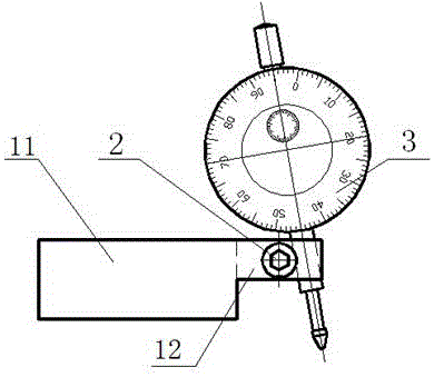
Figure 201921075486

A device for measuring the height difference of a cylinder liner undercut groove relates to the technical field of cylinder liner inspection and measurement devices. The utility model comprises a first watch seat, a second watch seat, a screw and a dial indicator. The first watch seat and the second watch seat are rectangular parallelepipeds, and the lower part of the second watch seat is milled to open the upper belt part of the cylinder sleeve. The upper part of the second watch seat is machined with an inclined hole, and another groove is machined through the inclined hole, which is convenient for clamping the dial indicator. One side of the groove is machined with threaded holes, and the other side is machined with through holes. After the dial indicator is installed and the position is adjusted, install screws to clamp the dial indicator. A V-shaped groove is opened at the lower part of the watch seat, which is convenient for placing the watch seat on the cylinder liner. The utility model has the advantages of simple structure, convenient measurement, high measurement accuracy and improved work efficiency. It can measure the height difference of various cylinder liner undercuts and has good versatility.

Figure 201921075486

Description

Device for measuring height difference of tool withdrawal groove of cylinder sleeve
Technical Field
The utility model relates to a cylinder jacket inspection measuring device's technical field.
Background
The tool withdrawal groove of the cylinder sleeve is positioned between the upper waistband and the lower end face of the support shoulder, and whether the tool withdrawal groove meets the design requirements of drawings or not directly influences the quality and the service life of a cylinder sleeve product. According to design requirements, the bottom and the upper waist of the tool withdrawal groove of some cylinder sleeves have the requirement of height difference, and the tolerance value of the size is small. Due to the particularity of the tool withdrawal groove structure, the measurement is inconvenient by using an ordinary micrometer and a vernier caliper. Even if the vernier caliper is used for measurement, the measurement accuracy is not high. Therefore, it is necessary to design a device for conveniently measuring the height difference of the tool withdrawal groove of the cylinder sleeve, so as to improve the measurement precision and the working efficiency.
Disclosure of Invention
The utility model aims at providing a simple structure, work efficiency is high, the good device of measurement cylinder jacket tool withdrawal groove difference in height of measurement effect.
A device for measuring the height difference of a tool withdrawal groove of a cylinder sleeve comprises a first gauge stand and a second gauge stand which are connected at one end, wherein the first gauge stand and the second gauge stand are cuboids; the height of the second gauge stand is lower than that of the first gauge stand, an inclined hole for penetrating the dial indicator is formed in the second gauge stand, and a groove is formed in the inclined hole; the length direction of percentage table and the length direction's of first gauge stand contained angle are the acute angle.
Preferably, the utility model discloses be located and set up the screw hole on the lateral wall of the second gauge stand of inclined hole department, set up the screw on the screw hole.
Preferably, the lower end surface of the first gauge stand of the utility model is provided with a V-shaped groove.
Preferably, the dial indicator of the utility model is a 0-10mm Ham dial indicator.
The utility model adopts the above technical scheme, compare with prior art and have following advantage:
1. the utility model discloses a promote first gauge stand and sheathe in the cylinder and remove to drive the percentage table and remove, according to removing the data difference that the in-process obtained, measure and obtain the difference in height of cylinder jacket escape groove bottom and last waistband, simple structure, it is efficient, measuring speed is fast.
2. The utility model discloses offer the groove in inclined hole department, utilize the fixed percentage table of clamping-force in groove, simple structure is convenient for measure.
3. The utility model discloses a cylinder jacket of multiple model can be measured to the height of percentage table is adjusted to the screw, and application scope is wide.
4. The utility model discloses a lower surface setting of first gauge stand and the V type recess that cylinder jacket external diameter is suitable for can follow the linear direction and remove, and measurement accuracy is high, has reduced measuring error.
Drawings
Fig. 1 is a schematic structural diagram of the present invention.
Fig. 2 is a schematic diagram of the position relationship between the inclined hole and the groove of the present invention.
Fig. 3 is a schematic view of the state of the measuring cylinder jacket with the waistband of the present invention.
Fig. 4 is the schematic view of the state of the measuring cylinder sleeve retracting slot bottom of the utility model.
Detailed Description
The technical scheme of the utility model is explained in detail with the attached drawings as follows:
as shown in fig. 1, a device for measuring a height difference of a tool withdrawal groove of a cylinder liner comprises a first gauge stand 11 and a second gauge stand 12, wherein one ends of the first gauge stand 11 and the second gauge stand 12 are connected, and the first gauge stand 11 and the second gauge stand 12 are cuboids; the height of the second gauge stand 12 is lower than that of the first gauge stand 11, an inclined hole for penetrating the dial indicator 3 is formed in the second gauge stand 12, and a groove 4 is formed in the inclined hole; the length direction of the dial indicator 3 and the length direction of the first gauge stand 11 form an acute angle.
As shown in fig. 1, the utility model discloses set up the screw hole on the lateral wall of second gauge stand 12 that is located inclined hole department, set up screw 2 on the screw hole.
The utility model discloses the lower terminal surface of first gauge stand 11 sets up V type recess (not seen in the figure).
The utility model discloses a percentage table 3 is 0-10 mm's the percentage table of hayage.
As shown in fig. 1 to 4: the utility model discloses a first gauge stand 11, second gauge stand 12, screw 2, percentage table 3. The first gauge stand 11 and the second gauge stand 12 are cuboids, and the lower part of the second gauge stand 12 is milled to make the upper waistband part of the cylinder sleeve open. An inclined hole is processed on the upper portion of the second gauge stand 12, and a groove 4 penetrates through the inclined hole, so that the dial indicator 3 can be conveniently clamped. One side of the side surface of the groove 4 is provided with a threaded hole, the other side of the side surface of the groove 4 is provided with a through hole, and after the dial indicator 3 is arranged and the position is adjusted, the screw 2 is arranged to clamp the dial indicator 3. The lower part of the first gauge stand 11 is provided with a V-shaped groove, so that the gauge stand is conveniently placed on the cylinder sleeve.
The utility model discloses when using, put the gauge stand on the cylinder jacket excircle, make percentage table 3's gauge head be located the cylinder jacket waistband position, write down 3 pointer readings of percentage table. And then moving the position of the gauge stand to enable the measuring head of the dial indicator 3 to be positioned at the bottom position of the tool withdrawal groove of the cylinder sleeve, and recording the reading of the pointer of the dial indicator 3. The height difference between the tool withdrawal groove of the cylinder sleeve and the upper waistband can be measured through the difference value of the two sets of data.
The utility model discloses simple structure, convenient measurement, measurement accuracy is high, has improved work efficiency. The measuring device can measure the height difference of the tool withdrawal grooves of various cylinder sleeves and has good universality.
The above description is only for the purpose of illustrating the technical solutions of the present invention and not for the purpose of limiting the same, and other modifications or equivalent replacements made by those of ordinary skill in the art to the technical solutions of the present invention should be covered within the scope of the claims of the present invention as long as they do not depart from the spirit and scope of the technical solutions of the present invention.

Claims (4)

1. A device for measuring the height difference of a tool withdrawal groove of a cylinder sleeve is characterized by comprising a first gauge stand (11) and a second gauge stand (12) which are connected at one end, wherein the first gauge stand (11) and the second gauge stand (12) are cuboids; the height of the second gauge stand (12) is lower than that of the first gauge stand (11), an inclined hole for penetrating the dial indicator (3) is formed in the second gauge stand (12), and a groove (4) is formed in the inclined hole; the included angle between the length direction of the dial indicator (3) and the length direction of the first gauge stand (11) is an acute angle.
2. The apparatus for measuring the height difference of the tool withdrawal groove of the cylinder liner according to claim 1, wherein the sidewall of the second gauge stand (12) at the inclined hole is provided with a threaded hole, and the threaded hole is provided with a screw (2).
3. The apparatus for measuring the tool withdrawal height difference of cylinder liner according to claim 1, wherein the lower end surface of the first gauge stand (11) is provided with a V-shaped groove.
4. The device for measuring the height difference of the tool recession of the cylinder liner according to claim 1, wherein the dial indicator (3) is a 0-10mm Hamameter.
CN201921075486.XU 2019-07-10 2019-07-10 A device for measuring the height difference of the undercut groove of a cylinder liner Active CN210198255U (en)

Priority Applications (1)

Application Number Priority Date Filing Date Title
CN201921075486.XU CN210198255U (en) 2019-07-10 2019-07-10 A device for measuring the height difference of the undercut groove of a cylinder liner

Applications Claiming Priority (1)

Application Number Priority Date Filing Date Title
CN201921075486.XU CN210198255U (en) 2019-07-10 2019-07-10 A device for measuring the height difference of the undercut groove of a cylinder liner

Publications (1)

Publication Number Publication Date
CN210198255U true CN210198255U (en) 2020-03-27

Family

ID=69866643

Family Applications (1)

Application Number Title Priority Date Filing Date
CN201921075486.XU Active CN210198255U (en) 2019-07-10 2019-07-10 A device for measuring the height difference of the undercut groove of a cylinder liner

Country Status (1)

Country Link
CN (1) CN210198255U (en)

Cited By (3)

* Cited by examiner, † Cited by third party
Publication number Priority date Publication date Assignee Title
CN112146553A (en) * 2020-09-24 2020-12-29 贵州凯星液力传动机械有限公司 Inner inclined hole position size measuring device and design and use method thereof
CN115218746A (en) * 2021-04-20 2022-10-21 中航西飞民用飞机有限责任公司 A method and device for measuring the protrusion of a wire boring machine tool
CN117817441A (en) * 2024-01-16 2024-04-05 中国船舶集团有限公司第七〇七研究所 A method for measuring the undercut groove of a motor shaft shoulder

Cited By (4)

* Cited by examiner, † Cited by third party
Publication number Priority date Publication date Assignee Title
CN112146553A (en) * 2020-09-24 2020-12-29 贵州凯星液力传动机械有限公司 Inner inclined hole position size measuring device and design and use method thereof
CN112146553B (en) * 2020-09-24 2022-06-10 贵州凯星液力传动机械有限公司 Design method and use method of inner inclined hole position size measuring device
CN115218746A (en) * 2021-04-20 2022-10-21 中航西飞民用飞机有限责任公司 A method and device for measuring the protrusion of a wire boring machine tool
CN117817441A (en) * 2024-01-16 2024-04-05 中国船舶集团有限公司第七〇七研究所 A method for measuring the undercut groove of a motor shaft shoulder

Similar Documents

Publication Publication Date Title
CN203893793U (en) Adjustable depth detecting device used for inclined holes
CN208860272U (en) A kind of two hole center distance cubing
CN216558635U (en) Detection tool for rapidly detecting length of thrust surface of shaft workpiece
CN211317140U (en) Deep hole step height measuring device
CN202329460U (en) Taper hole measurement device
CN104713440A (en) Quantitative measurement caliper gauge
CN102494600B (en) Multidimension measuring apparatus of high speed processing handle
CN206281428U (en) Groove measuring gage
CN204831130U (en) Hand -held type slot pitch detection device
CN201787914U (en) Digital Outer Conicity Measuring Instrument
CN203824505U (en) Testing fixture used for detecting workpiece planeness
CN203605885U (en) Crankcase comprehensive test tool
CN206944901U (en) A kind of micro- depth survey frock of magnetic ferrite magnetic core ladder
CN110836625A (en) A cantilever type high-precision length measuring device
CN204902746U (en) A detect auxiliary device that is used for a bolt word groove symmetry
CN204421793U (en) A kind of quantitative measurment calliper
CN205448927U (en) A gauge for measuring internal thread degree of depth
CN203572473U (en) Positioning tooling applied to cylinder taper measurement
CN210464308U (en) High-precision measuring device for groove wall thickness
CN210533227U (en) Static precision measuring device for guide rail pair
CN203605849U (en) Piston comprehensive test tool
CN210741308U (en) A cantilever type high-precision length measuring device
CN107966090A (en) A kind of probe-type measurement device able to quickly change for detecting narrow slot and thin blind hole depth
CN219798145U (en) Motor shaft boss face size detection tool
CN112648906A (en) Portable simple diameter measuring tool for large-diameter inner hole and using method thereof

Legal Events

Date Code Title Description
GR01 Patent grant
GR01 Patent grant
EE01 Entry into force of recordation of patent licensing contract

Assignee: JIANGSU AIJISI HAIZHU MACHINERY Co.,Ltd.

Assignor: JIANGSU HUACHEN CYLINDER LINER Inc.,Ltd.

Contract record no.: X2024980020378

Denomination of utility model: A device for measuring the height difference of the cylinder liner return groove

Granted publication date: 20200327

License type: Common License

Record date: 20241024